Infiniti G35 2003 - 2003 ELECTRICAL Fuses & Circuit Breakers - G35
Infiniti G35 2003 - IDENTIFICATION
WARNING: Vehicle is equipped with air bag supplemental restraint system. Before attempting ANY repairs involving steering column, instrument panel or related components, see AIR BAG SAFETY PRECAUTIONS and DISABLING & ACTIVATING AIR BAG SYSTEM in AIR BAG RESTRAINT SYSTEMS article in RESTRAINTS.
WARNING: Always disconnect battery ground cable before servicing high-current fuses. It is recommended that high-current fuses be replaced by a qualified technician.
CAUTION: When battery is disconnected, vehicle computer and memory systems may lose memory data. Driveability problems may exist until computer systems have completed a relearn cycle. See COMPUTER RELEARN PROCEDURES article in GENERAL INFORMATION before disconnecting battery.
Infiniti G35 2003 - ENGINE COMPARTMENT JUNCTION & RELAY BLOCKS
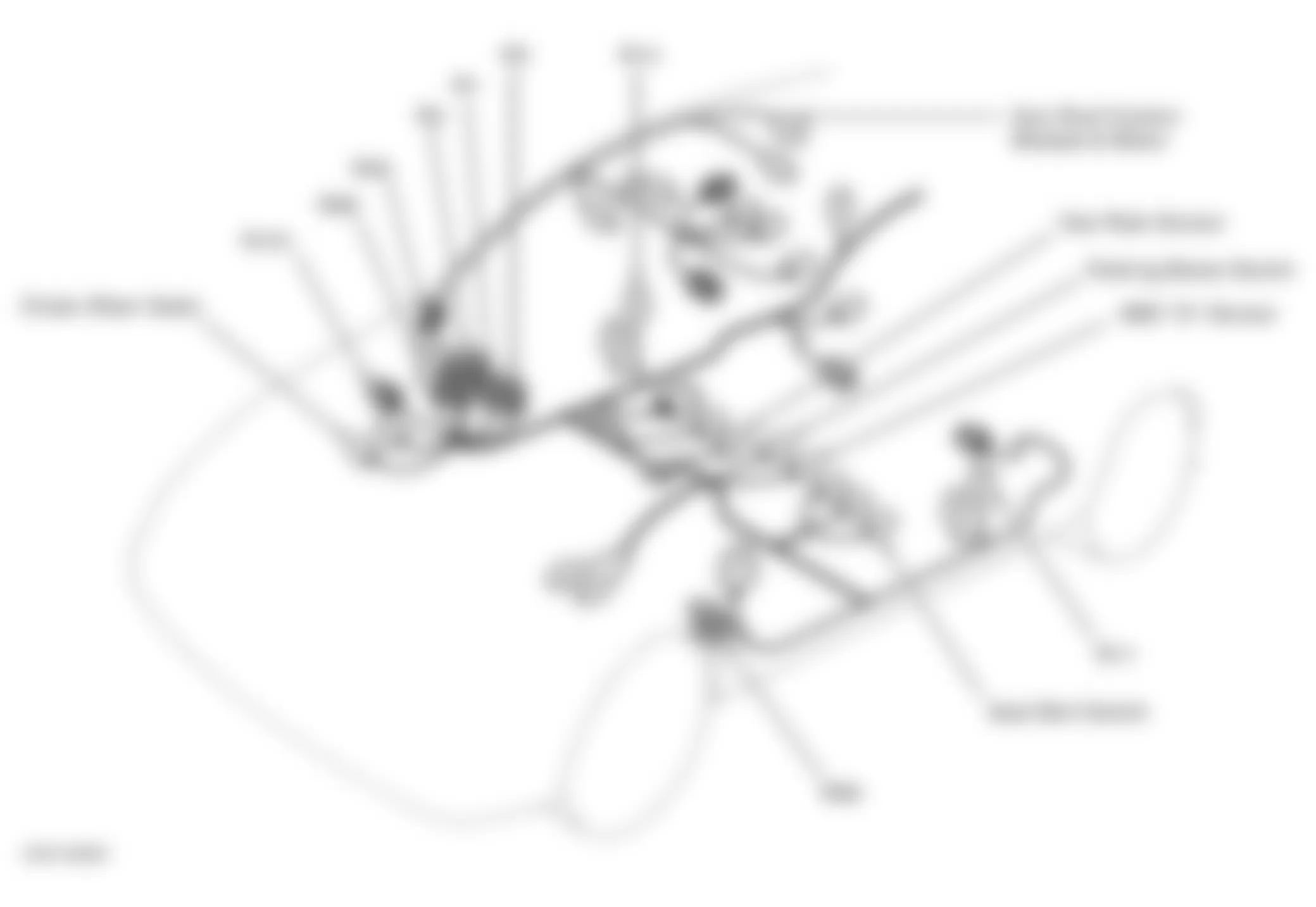
NOTE: For engine compartment fuse, fusible link and relay box locations, see Fig. 1.
Component Locations
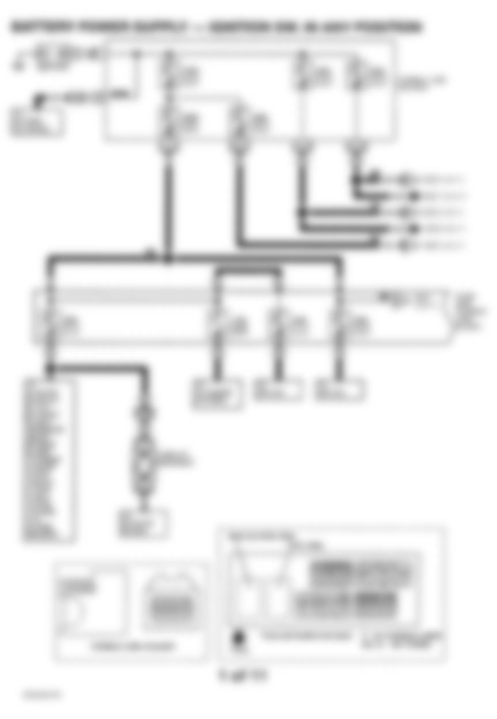
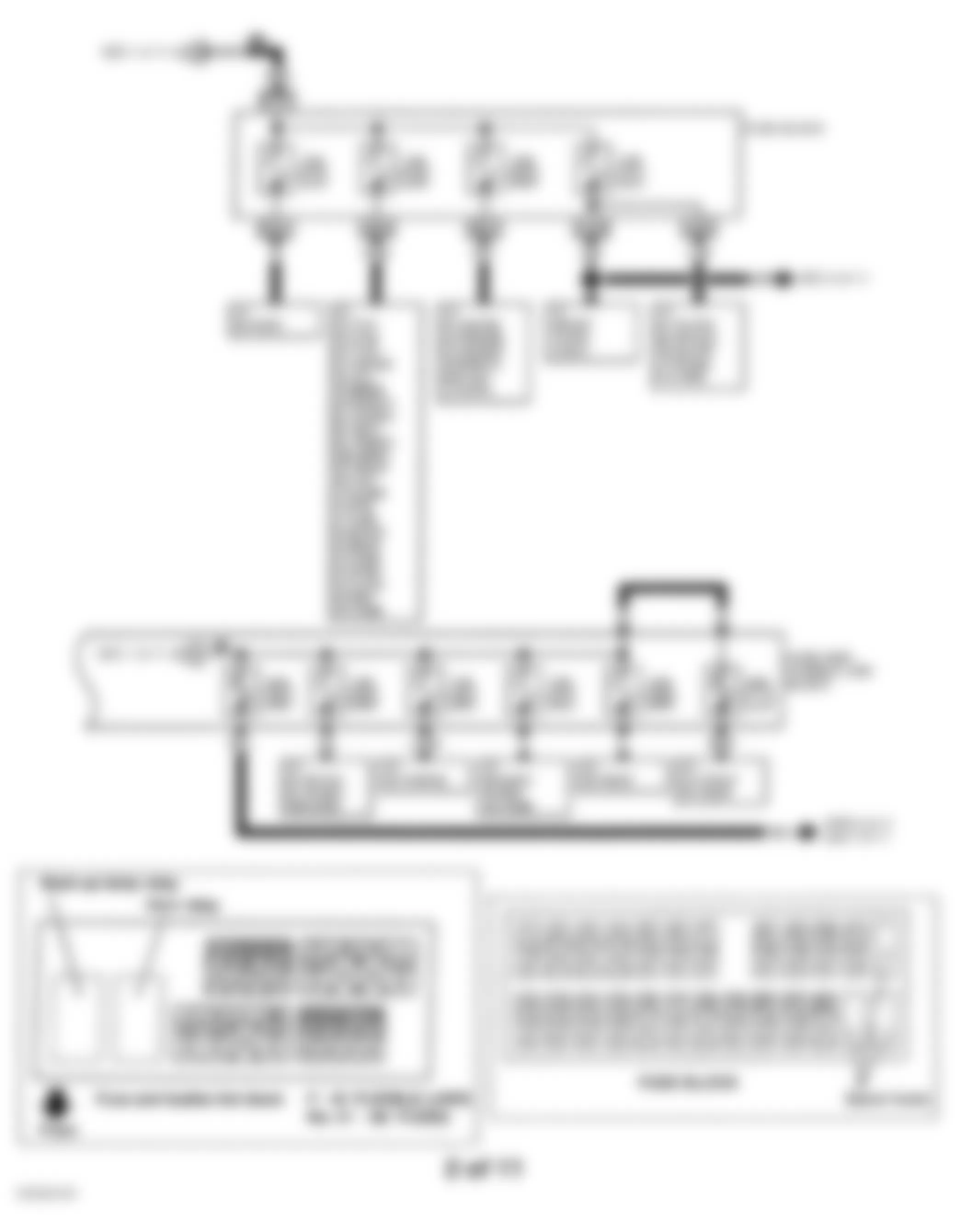
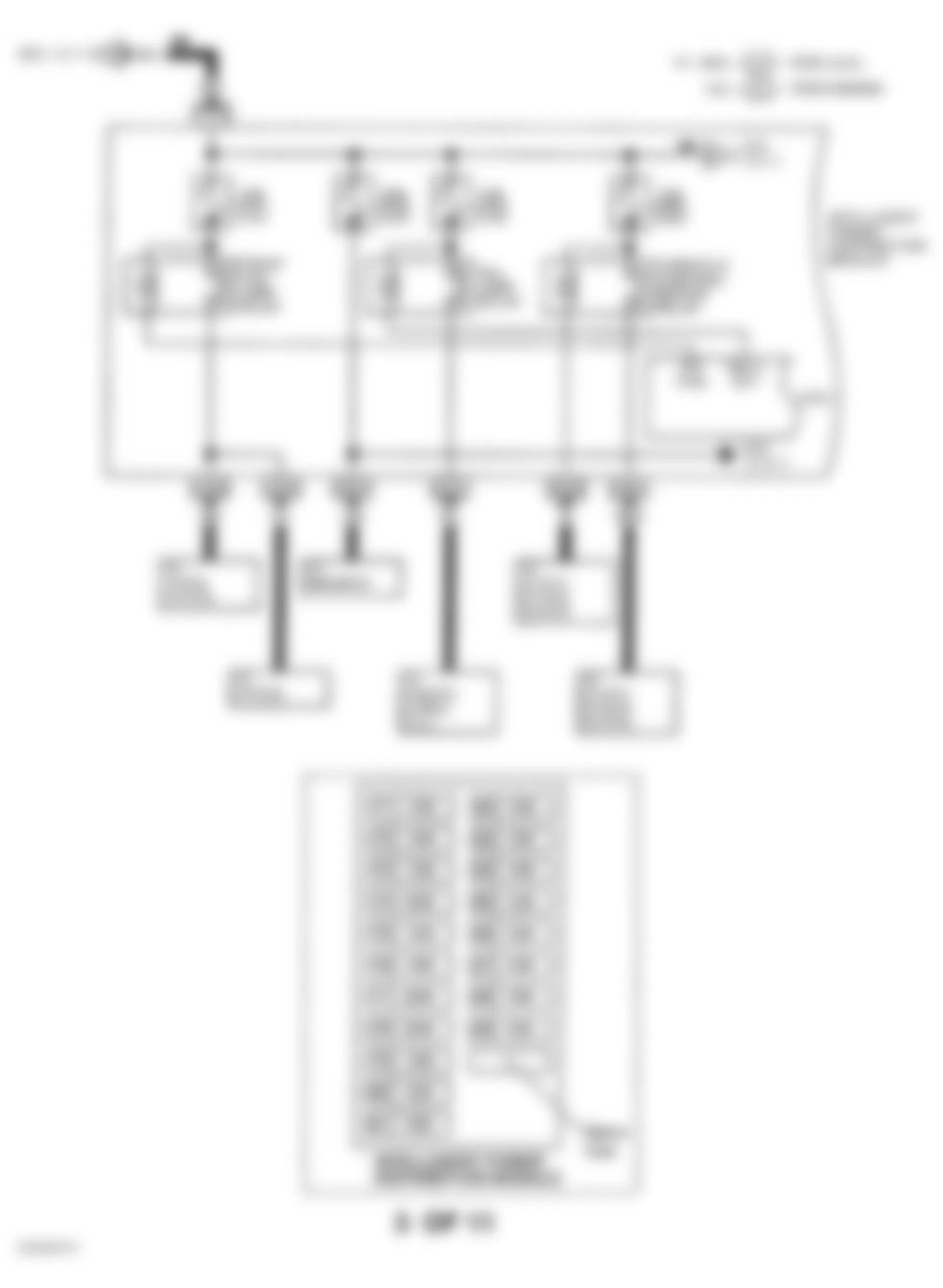
- Fuse and fusible link block is located at passenger's side of engine compartment. For component identification, see Fig. 6 and Fig. 7 . For circuit wiring diagram, see POWER DISTRIBUTION in SYSTEM WIRING DIAGRAMS article.
- Relay box No. 1 is located at passenger's side of engine compartment. For component locations, see Fig. 2.
- Relay box No. 2 is located at driver's side of engine compartment. For component locations, see Fig. 3.
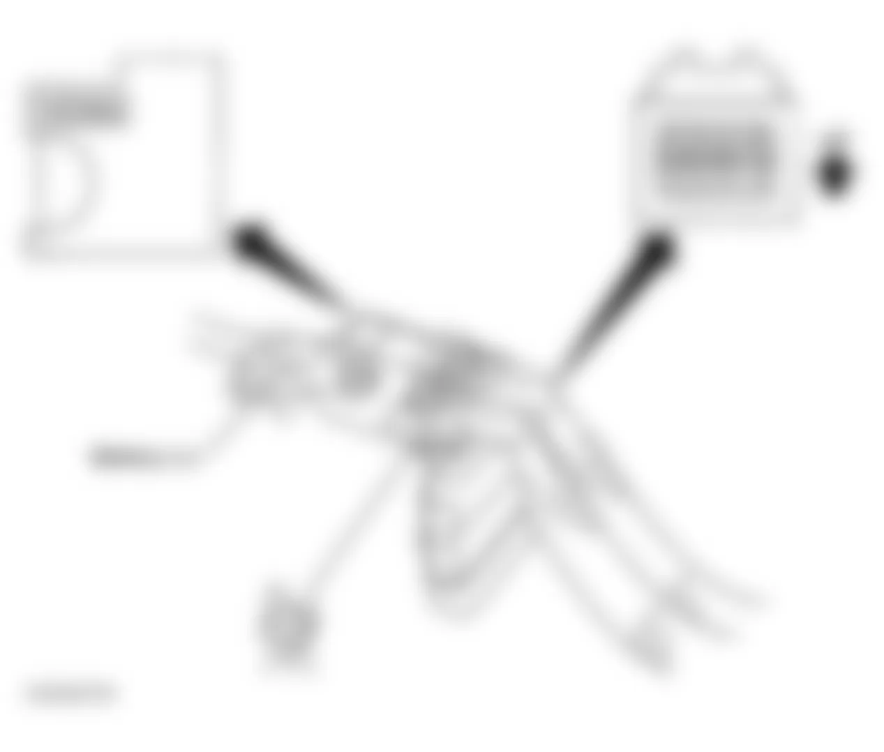
- Fusible link holder is located at passenger's side of engine compartment near battery connectors. For component locations, see Fig. 4. For component identification, see Fig. 6 and Fig. 15 . For circuit wiring diagram, see POWER DISTRIBUTION in SYSTEM WIRING DIAGRAMS article.
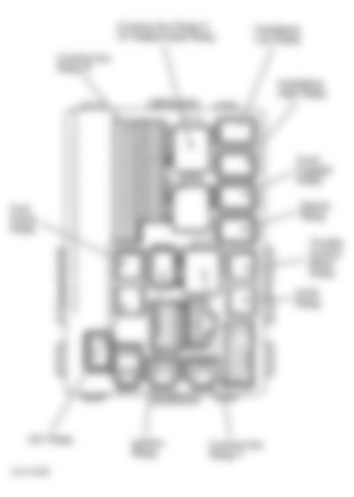
- Intelligent Power Distribution Module (IPDM) is located at passenger's side of engine compartment. For relay locations, see Fig. 5. For component identification, see Fig. 8-Fig. 10 and Fig. 14-Fig. 16 . For circuit wiring diagram, see POWER DISTRIBUTION in SYSTEM WIRING DIAGRAMS article.

Fig. 2: Infiniti G35 2003 - Component Locations - Locating Relay Box No. 1 Relays
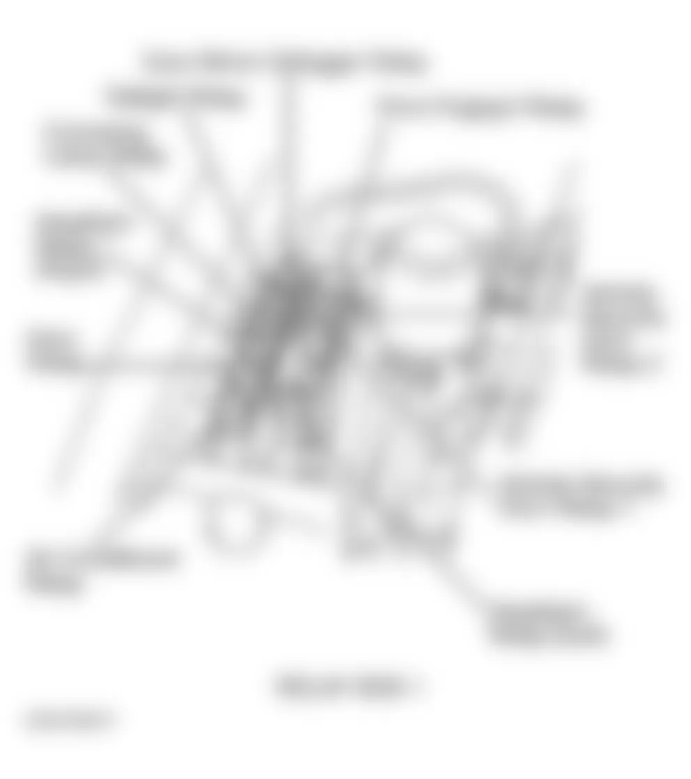
Fig. 3: Infiniti G35 2003 - Component Locations - Locating Relay Box No. 2 Relays
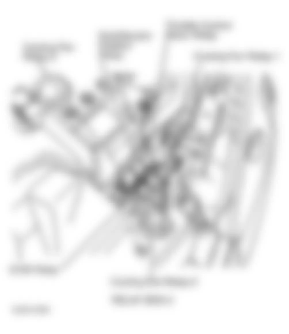
Fig. 4: Infiniti G35 2003 - Component Locations - Locating Fusible Link Holder Components
Infiniti G35 2003 - INSTRUMENT PANEL JUNCTION & RELAY BLOCKS
NOTE: For instrument panel and passenger area fuse block, relay, control module and unit locations, see Fig. 17 and Fig. 18 .
Component Locations
- Circuit breaker is located behind driver's side kick panel. For component identification, see Fig. 6.
- Fuse block is located behind driver's side kick panel. For component identification, see Fig. 7, Fig. 11-Fig. 14 and Fig. 16 . For circuit wiring diagram, see POWER DISTRIBUTION in SYSTEM WIRING DIAGRAMS article.
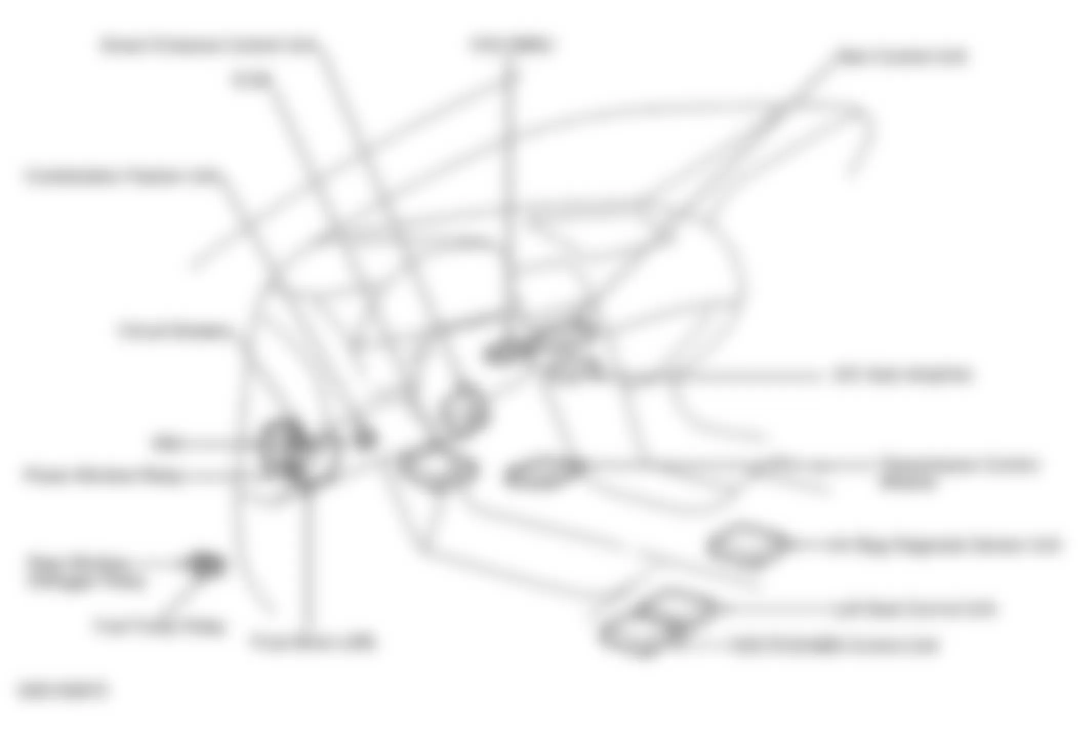
Fig. 18: Infiniti G35 2003 - Component Locations - Locating Luggage Compartment Relay