Infiniti Q45 1990 - 1990 ENGINE PERFORMANCE Self-Diagnostics - Q45
Infiniti Q45 1990 - INTRODUCTION
If no faults were found while performing BASIC TESTING , proceed with ENTERING SELF-DIAGNOSTICS. If no fault codes or only pass codes are present, proceed to TESTS W/O CODES article in this section for diagnosis by symptom (i.e. ROUGH IDLE, NO START, etc.).
Infiniti Q45 1990 - SELF-DIAGNOSTIC SYSTEM
The self-diagnostic system is used for diagnosing malfunctions of Electronic Concentrated Control System (ECCS) sensors and actuators. The Electronic Control Unit (ECU) has 2 available diagnostic modes. Before entering self-diagnostics, perform BASIC TESTING . This eliminates wasted diagnostic time and invalid diagnostic results.
NOTE: When performing BASIC TESTING , be careful not to erase any diagnostic information stored in ECU memory.
Infiniti Q45 1990 - HARD FAILURES
Hard failures will cause CHECK ENGINE light to illuminate and remain on until problem is repaired. If light comes on and remains on (light may flash) during vehicle operation, cause of malfunction must be determined using diagnostic (code) charts. If a sensor fails, control unit will use a substitute value in its calculations to continue engine operation. In this condition, commonly known as limp-in mode, the vehicle runs but driveability will not be optimum.
Infiniti Q45 1990 - INTERMITTENT FAILURES
Intermittent failures may cause CHECK ENGINE light to flicker or illuminate and go out after the intermittent fault goes away. However, the corresponding trouble code will be stored in ECU memory. Not all trouble codes will illuminate CHECK ENGINE light. If related fault does not reoccur within a certain time frame, related trouble code will be erased from ECU memory. Intermittent failures may be caused by a sensor, connector or wiring related problems. See INTERMITTENTS in TESTS W/O CODES article.
NOTE: Follow proper diagnostic routine when diagnosing the system. See DIAGNOSTIC ROUTINE table.
Infiniti Q45 1990 DIAGNOSTIC ROUTINE
Procedure Order Basic Diagnostic Procedures 1st Entering Diagnostics 2nd Retrieving Trouble Codes 3rd Symptoms (1) 4th Intermittents (1) 5th
(1) Symptoms and intermittents are covered in TESTS W/O CODES article.
Infiniti Q45 1990 - CHECK ENGINE LIGHT
NOTE: All trouble codes do not activate CHECK ENGINE LIGHT.
All models are equipped with a CHECK ENGINE light. As a bulb check, light will illuminate when the ignition is turned on and engine is not running.
On California models, CHECK ENGINE light illuminates when a fault is detected with engine running. A corresponding trouble code will set in ECU memory. CHECK ENGINE light also illuminates if ECU or crank angle sensor malfunctions.
On Federal models, CHECK ENGINE light illuminates only when ECU or crank angle sensor malfunctions with engine running.
Infiniti Q45 1990 - DIAGNOSTIC MODES
The self-diagnostic system can detect ECCS malfunctions and store related trouble code. Intermittent codes are also stored. All codes are stored until cleared from memory. If an intermittent does not reoccur within 50 ignition key cycles, it will be cleared from memory.
Switching modes is not possible when the engine is running. During diagnosis, the self-diagnostic system will automatically return to Mode I from Mode II when the ignition switch is turned off.
Infiniti Q45 1990 - MODE I
This is normal operating mode. In this mode, the CHECK ENGINE light and Red Light Emitting Diode (LED) inspection light in ECU stay on when the ignition is turned on, engine off (bulb check). If the engine is started, CHECK ENGINE light and Red LED in ECU should turn off, unless a fault or trouble code is present (Calif. models) or if the ECU or crank angle sensor is malfunctioning (Calif. and Fed. models).
Infiniti Q45 1990 - MODE II
This is self-diagnostic mode for retrieving fault or trouble code(s). See RETRIEVING CODES. With the engine running, Mode II can monitor air/fuel mixture feedback control. The CHECK ENGINE light and Red LED in the ECU will flash on (lean) and off (rich) more than 5 times every 10 seconds with engine speed at 2000 RPM when system is in closed loop. The CHECK ENGINE light and Red LED do not flash remain on or off if system is in open loop.
Infiniti Q45 1990 - ECU LOCATION
The ECU is located behind the right kick panel.
Infiniti Q45 1990 - ENTERING SELF-DIAGNOSTICS
- Turn ignition switch to ON position, engine off. Using a small screwdriver, turn diagnostic mode selector on ECU fully clockwise. Wait at least 2 seconds and then turn diagnostic mode selector fully counterclockwise. Mode II self-diagnostic will result and the CHECK ENGINE light and the Red LED inspection light will flash trouble codes (if present).
- If engine is started at this stage, the CHECK ENGINE light and the Red LED inspection light will display the condition of the air/fuel mixture which is monitored by the O2 sensor or if the system is in closed or open loop.
Infiniti Q45 1990 - RETRIEVING CODES
NOTE: Mode II can retrieve trouble code(s) from self-diagnostic system.
Read trouble codes with either CHECK ENGINE light or Red LED inspection light on ECU. Trouble codes will flash after selecting Mode II.
Trouble codes are indicated by the number of flashes from CHECK ENGINE light or Red LED inspection light. Count the flashes. For example, 3 long (.6 second) flashes followed by 2 short (.3 second) flashes of CHECK ENGINE light or Red LED indicate a Code 32.
Infiniti Q45 1990 TROUBLE CODE IDENTIFICATION CHART
Code System Affected Probable Cause 11 (1) (2) Crank Angle Sensor (Q45) No crank signal 12 Airflow Meter Circuit Open/shorted circuit 13 Coolant Temp. Sensor Open/shorted circuit 14 Vehicle Speed Sensor (VSS) No VSS signal 21 (1) (2) Ign. Signal Circuit (Q45) Open/shorted circuit 31 ECU Signals not normal 32 EGR Function (Calif.) No EGR action 33 O2 Sensor (Left Bank-Q45) Open ckt/high O2 signal 34 (1) Knock Sensor (Q45) Open/shorted ckt 35 EGR Temp. Sensor (Calif.) Open/shorted ckt 43 Throttle Sensor Open/shorted ckt 45 Injector Leak (Calif.) Leak at injector(s) 51 Injector Circuit (Calif.) Injector doesn't work 53 O2 Sensor (Right Bank-Q45) Open ckt/high O2 signal 54 (1) Auto. Trans. Signal (Q45) Open signal transmission control unit 55 (1) No Malfunction (Q45) Normal condition
(1) These trouble code(s) not will activate CHECK ENGINE light.
(2) Check items causing a malfunction of crank angle sensor circuit first, if Codes 11 and 21 are present at same time.
Infiniti Q45 1990 - CLEARING CODES
NOTE: Ensure all diagnostic codes are accessed from ECU memory before disconnecting battery or switching from Mode II to Mode I.
Infiniti Q45 1990 - MEMORY ERASE
Stored memory can be erased by disconnecting battery or selecting Mode I after Mode II has been accessed.
Infiniti Q45 1990 - SUMMARY
If no hard fault codes (or only pass codes) are present, proceed to TESTS W/O CODES article for diagnosis by symptom (i.e. ROUGH IDLE, NO START, etc.) or intermittent diagnosis procedures.

Fig. 1: Infiniti Q45 1990 - Component Locations - Identifying Trouble Code Chart Symbols
Infiniti Q45 1990 - CODE 11: CRANK ANGLE SENSOR (Q45)
Fig. 2: Infiniti Q45 1990 - Component Locations - Q45 Code 11: Crank Angle Sensor Circuit Diagram


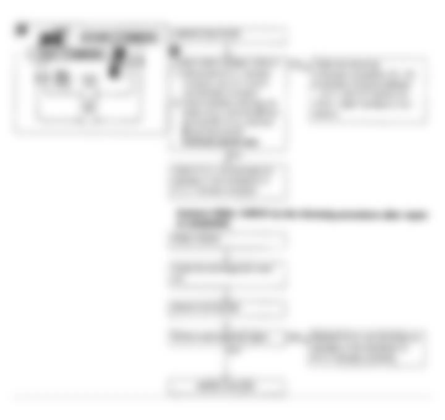
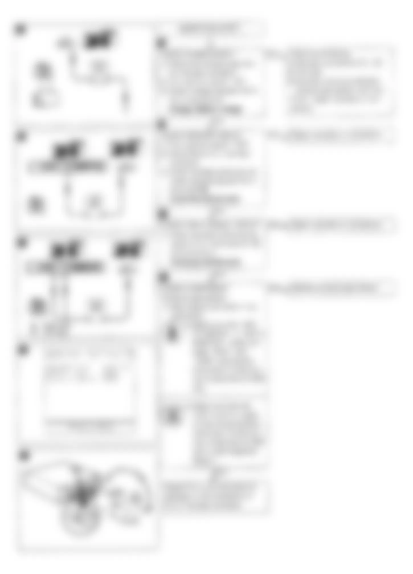
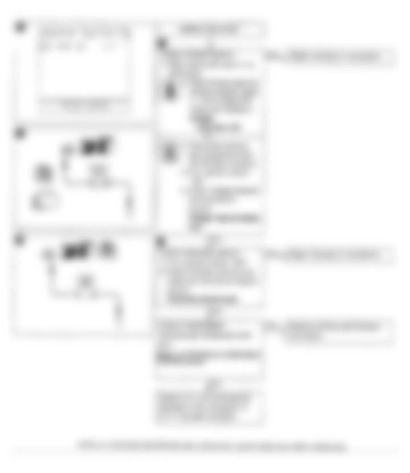
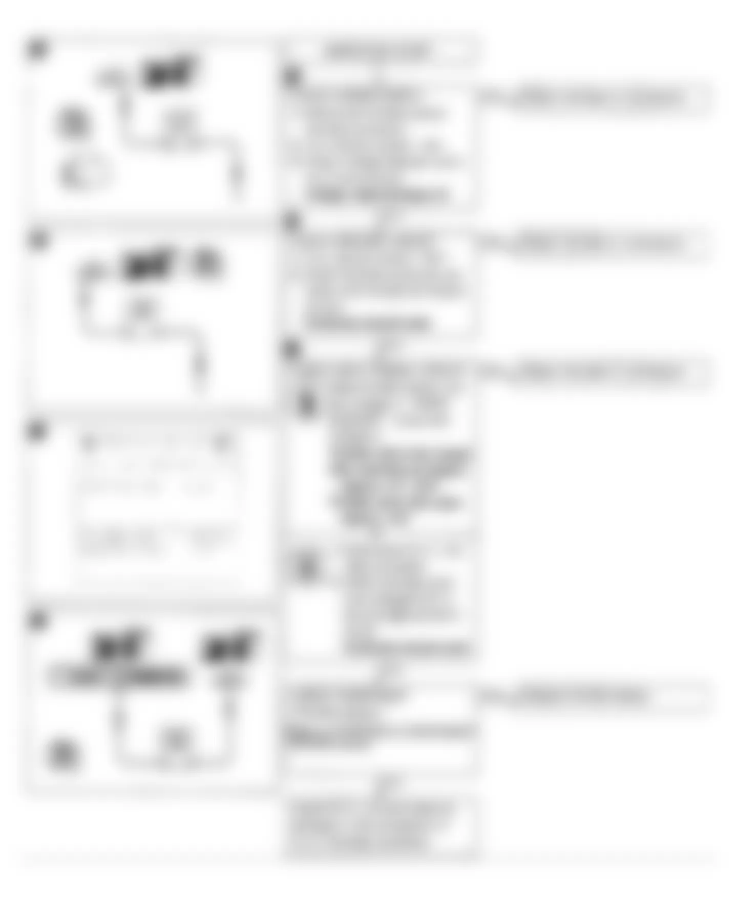
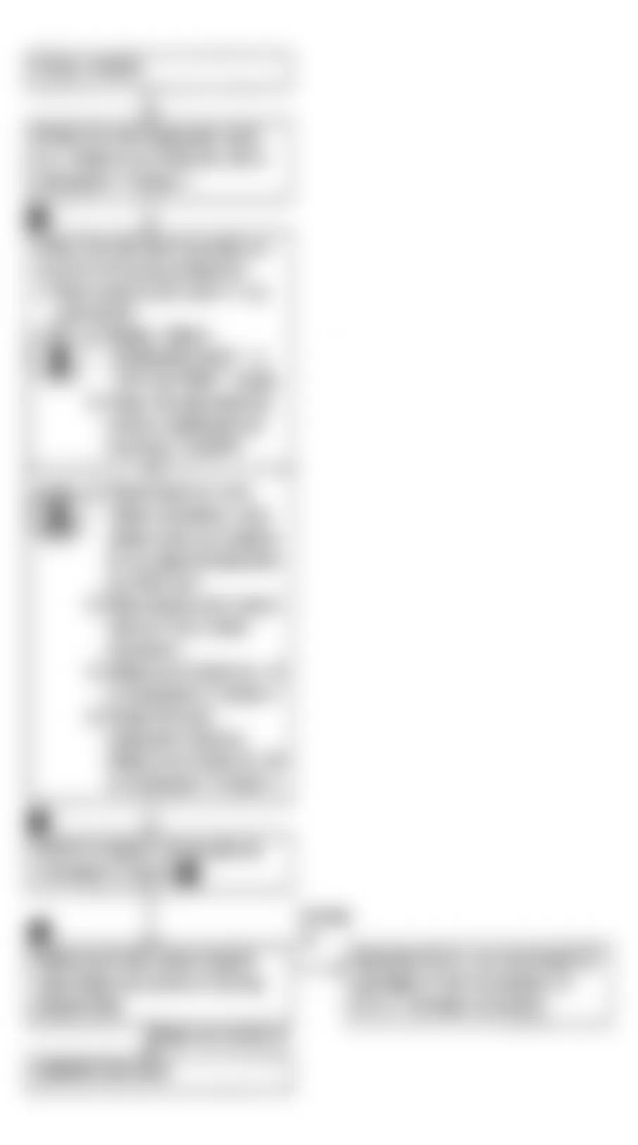
Fig. 4: Infiniti Q45 1990 - Component Locations - Q45 Code 11: Crank Angle Sensor Flow Chart

Infiniti Q45 1990 - CODE 12: AIRFLOW METER (Q45)
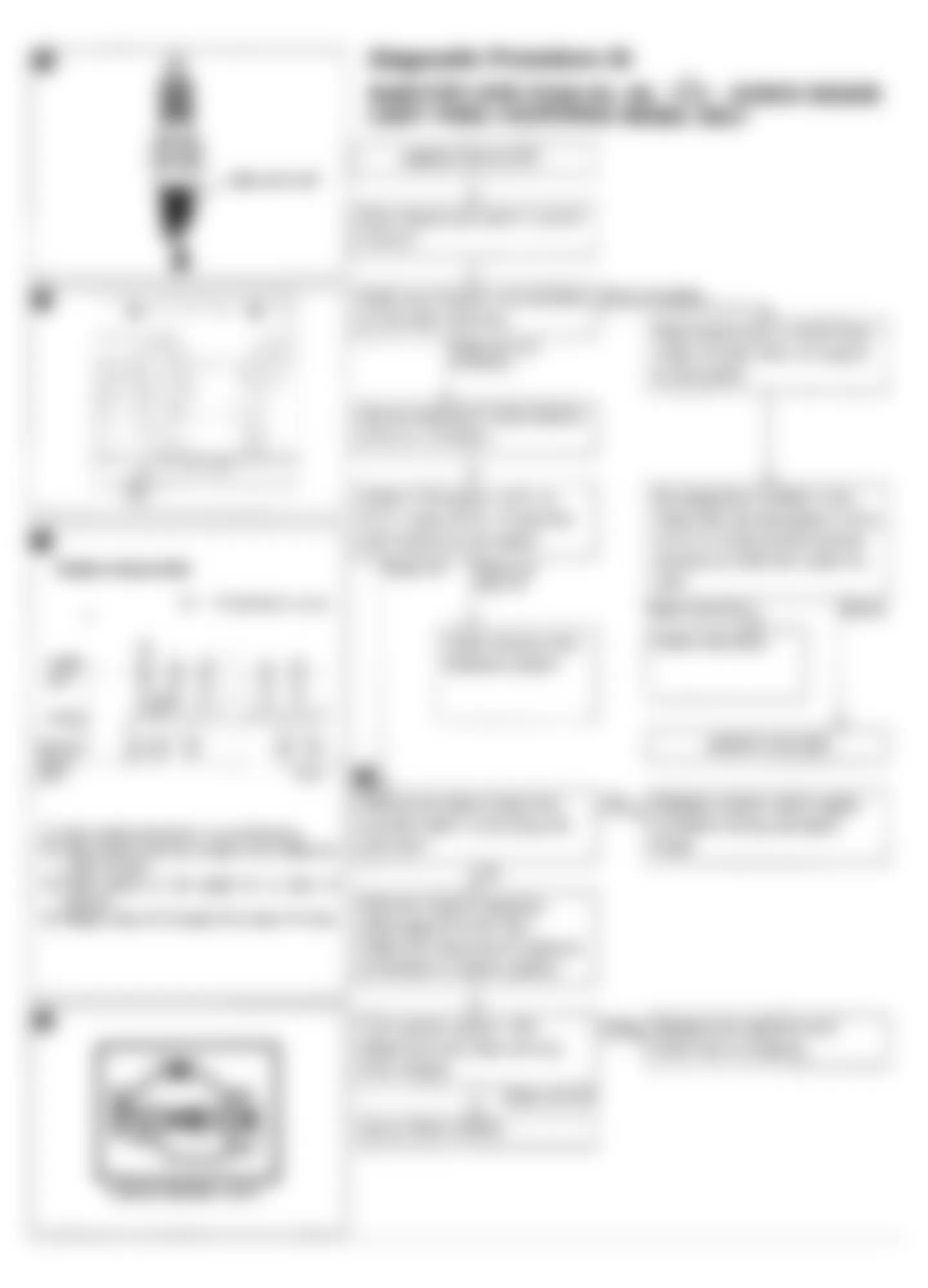
Fig. 5: Infiniti Q45 1990 - Component Locations - Q45 Code 12: Air Flow Meter Circuit Diagram
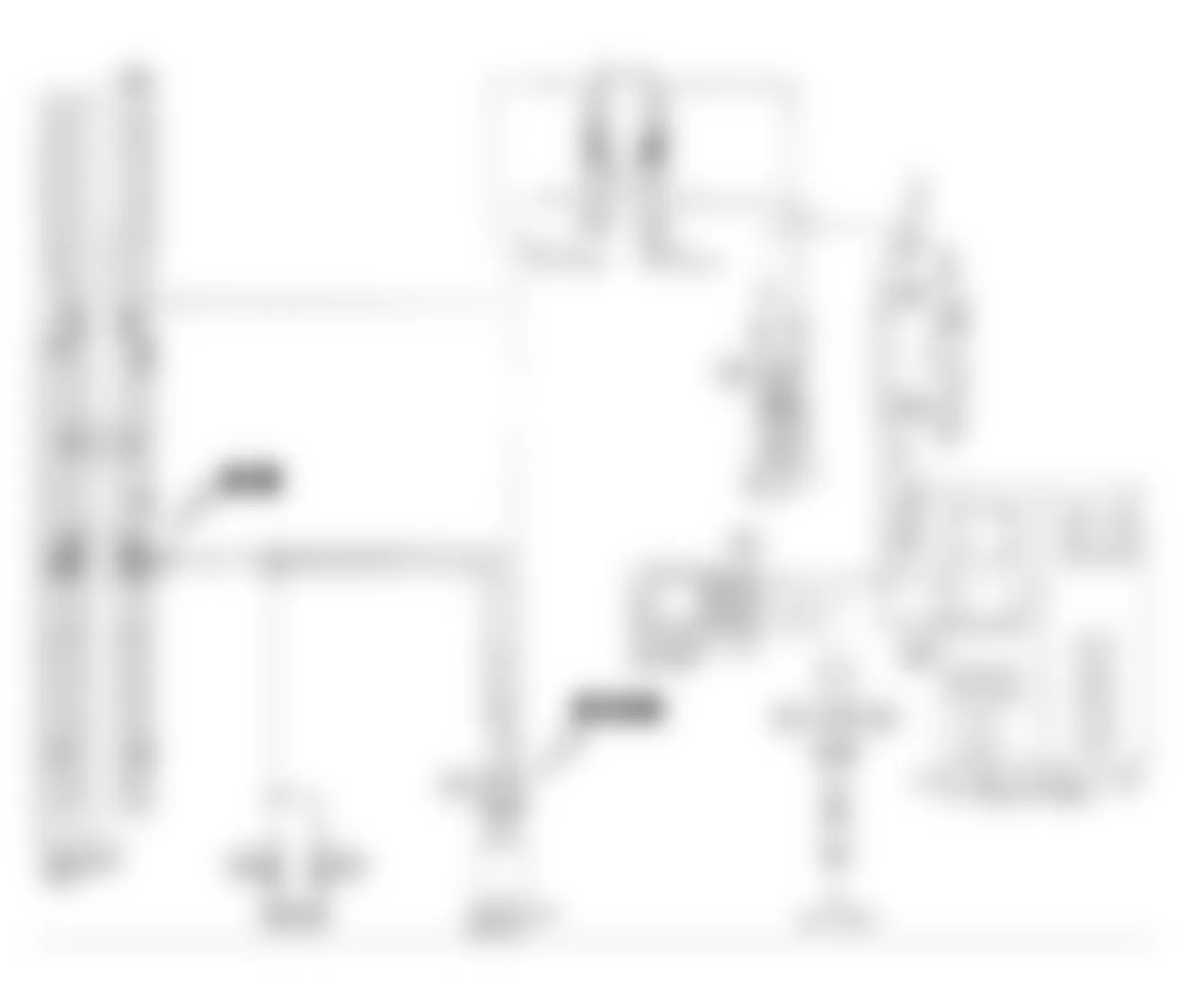
Fig. 6: Infiniti Q45 1990 - Component Locations - Q45 Code 12: Air Flow Meter & ECU Harness Location

Fig. 7: Infiniti Q45 1990 - Component Locations - Q45 Code 12: Air Flow Meter Flow Chart

Infiniti Q45 1990 - CODE 13: ENGINE (COOLANT) TEMP SENSOR (Q45)
Fig. 8: Infiniti Q45 1990 - Component Locations - Q45 Code 13: Engine Temp Sensor Circuit Diagram

Fig. 10: Infiniti Q45 1990 - Component Locations - Q45 Code 13: Engine Temp Sensor Flow Chart

Infiniti Q45 1990 - CODE 14: VEHICLE SPEED SENSOR (Q45)
Fig. 11: Infiniti Q45 1990 - Component Locations - Q45 Code 14: Vehicle Speed Sensor Circuit Diagram
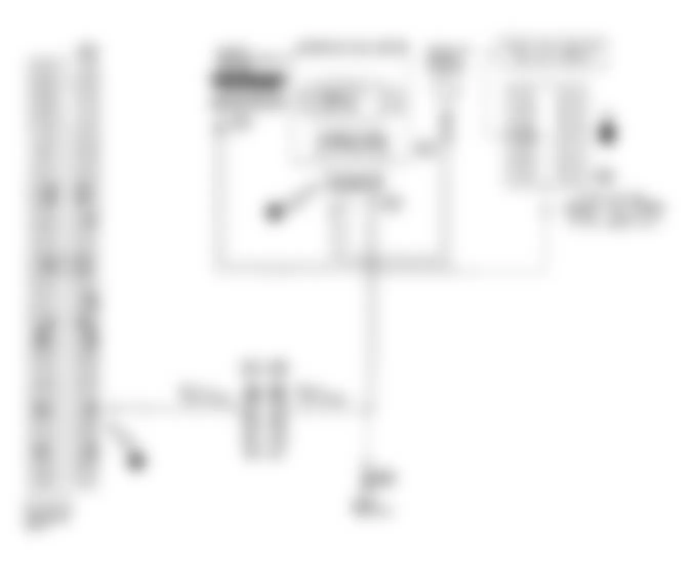
Fig. 12: Infiniti Q45 1990 - Component Locations - Q45 Code 14: ECU Harness Location

Fig. 13: Infiniti Q45 1990 - Component Locations - Q45 Code 14: Vehicle Speed Sensor Flow Chart
Infiniti Q45 1990 - CODE 21: IGNITION SIGNAL CIRCUIT (Q45)
Fig. 14: Infiniti Q45 1990 - Component Locations - Q45 Code 21: Ignition Signal Circuit Diagram
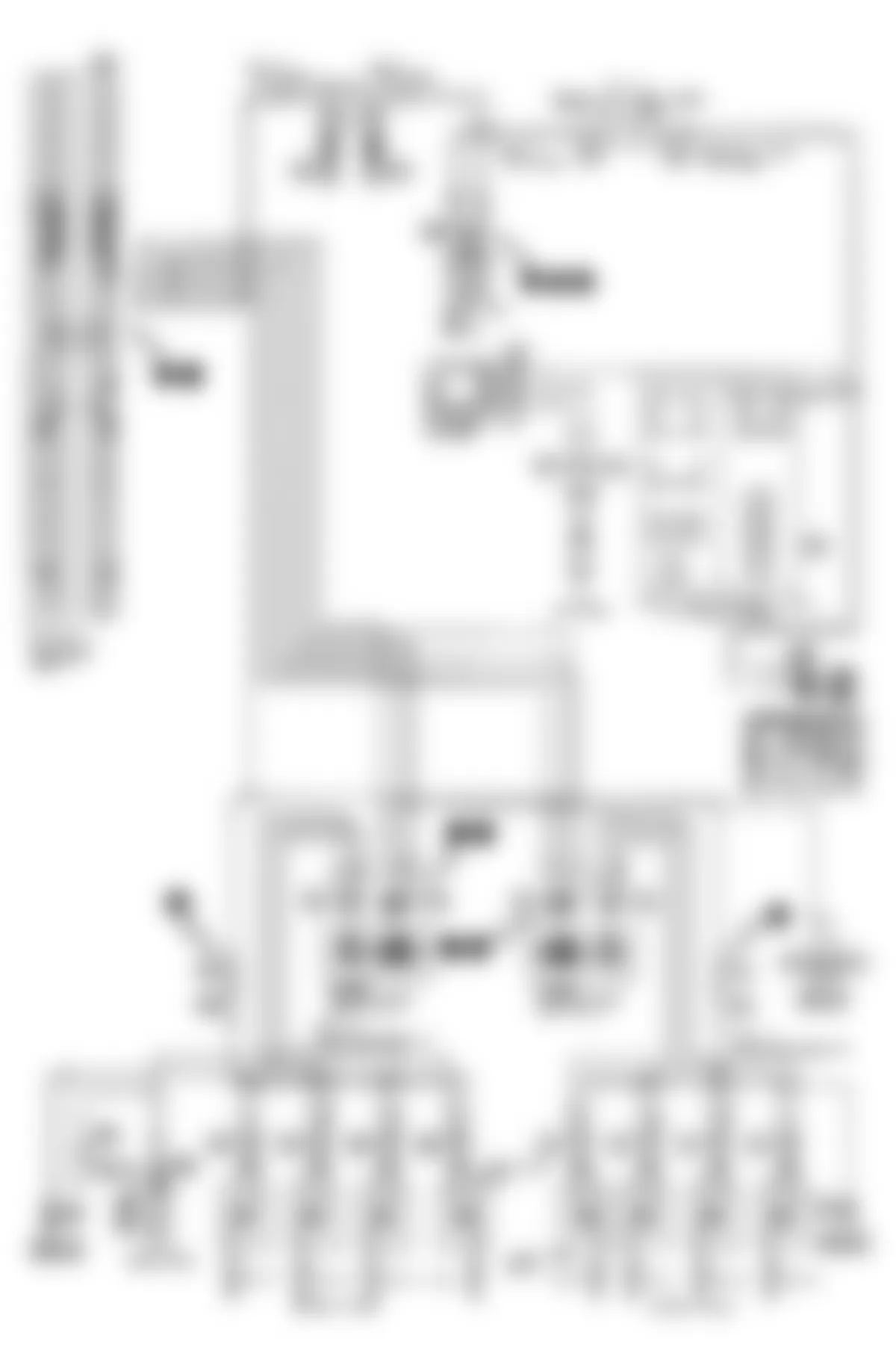
Fig. 16: Infiniti Q45 1990 - Component Locations - Q45 Code 21: Ignition Signal Flow Chart (1 of 2)
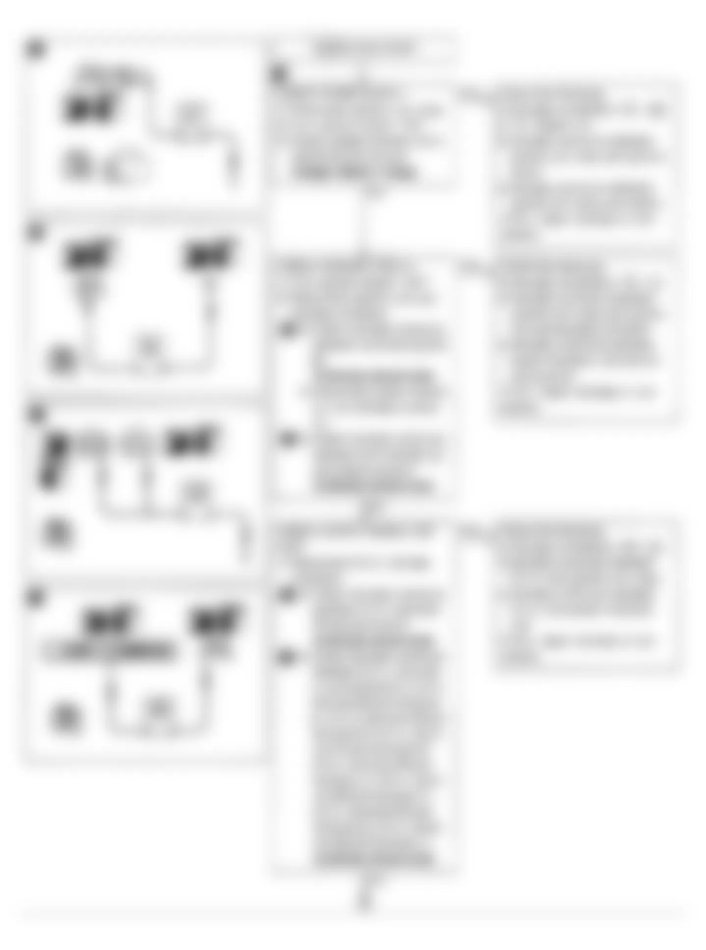
Fig. 17: Infiniti Q45 1990 - Component Locations - Q45 Code 21: Ignition Signal Flow Chart (2 of 2)

Infiniti Q45 1990 - CODE 31: ENGINE CONTROL UNIT (ECU) (Q45)
Fig. 18: Infiniti Q45 1990 - Component Locations - Q45 Code 31: Engine Control Unit (ECU) Flow Chart

Infiniti Q45 1990 - CODE 32: EGR SENSOR (Q45)
Fig. 19: Infiniti Q45 1990 - Component Locations - Q45 Code 32: EGR Sensor Circuit Diagram
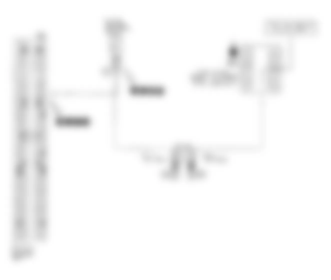

Fig. 21: Infiniti Q45 1990 - Component Locations - Q45 Code 32: EGR Sensor Flow Chart (1 of 2)

Fig. 22: Infiniti Q45 1990 - Component Locations - Q45 Code 32: EGR Sensor Flow Chart (2 of 2)

Infiniti Q45 1990 - CODE 33 & 53: LEFT & RIGHT OXYGEN SENSOR (Q45)

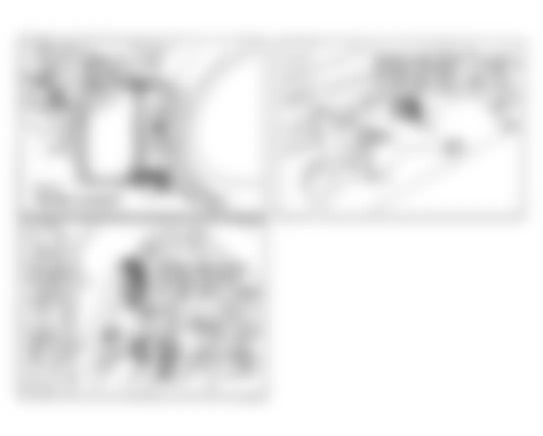
Fig. 25: Infiniti Q45 1990 - Component Locations - Q45 Code 33: Left & Right O2 Sensor Flow Chart
Infiniti Q45 1990 - CODE 34: KNOCK (DETONATION) SENSOR (Q45)
Fig. 26: Infiniti Q45 1990 - Component Locations - Q45 Code 34: Knock Sensor Circuit Diagram
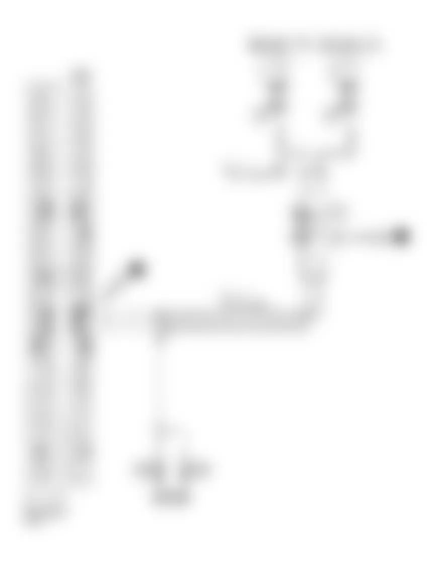

Fig. 28: Infiniti Q45 1990 - Component Locations - Q45 Code 34: Knock Sensor Flow Chart

Infiniti Q45 1990 - CODE 35: EGR TEMPERATURE SENSOR (Q45)
Fig. 29: Infiniti Q45 1990 - Component Locations - Q45 Code 35: EGR Temp Sensor Circuit Diagram

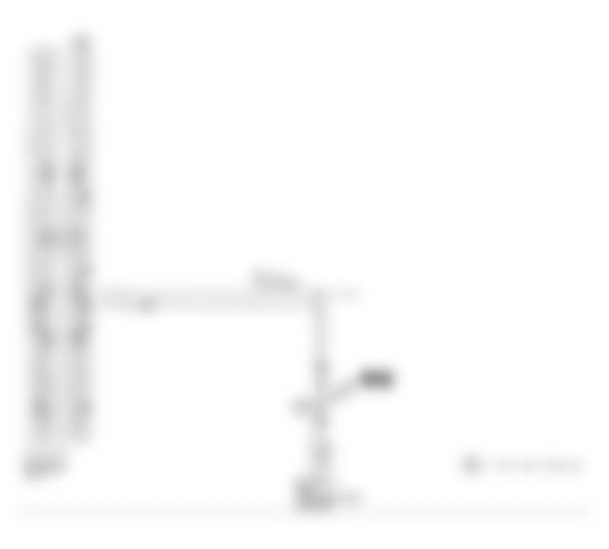
Fig. 31: Infiniti Q45 1990 - Component Locations - Q45 Code 35: EGR Temp Sensor Flow Chart
Infiniti Q45 1990 - CODE 43: THROTTLE POSITION SENSOR (Q45)
Fig. 32: Infiniti Q45 1990 - Component Locations - Q45 Code 43: TPS Circuit Diagram


Fig. 34: Infiniti Q45 1990 - Component Locations - Q45 Code 43: TPS Flow Chart
Infiniti Q45 1990 - CODE 45: INJECTOR LEAK (Q45)
Fig. 35: Infiniti Q45 1990 - Component Locations - Q45 Code 45: Injector Leak Flow Chart (1 of 2)
Infiniti Q45 1990 - CODE 51: INJECTOR CIRCUIT (Q45)
Fig. 37: Infiniti Q45 1990 - Component Locations - Q45 Code 51: Injector Circuit Diagram
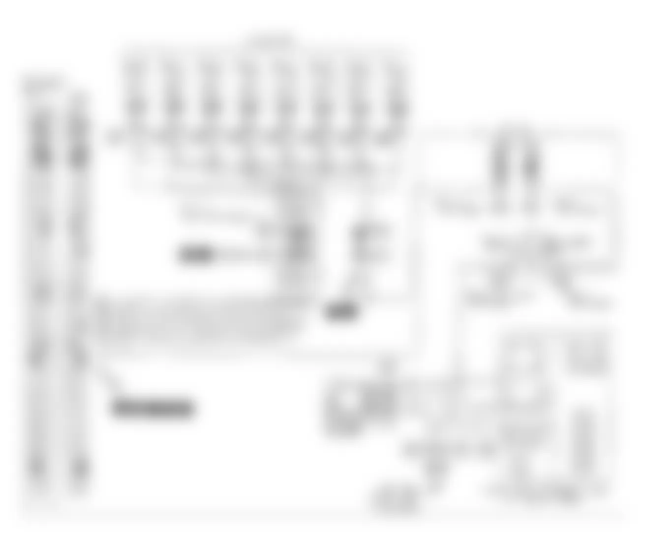

Fig. 39: Infiniti Q45 1990 - Component Locations - Q45 Code 51: Injector Flow Chart

Infiniti Q45 1990 - CODE 54: AUTOMATIC TRANSMISSION SIGNAL (Q45)
Fig. 40: Infiniti Q45 1990 - Component Locations - Q45 Code 54: Auto Trans Signal Circuit Diagram
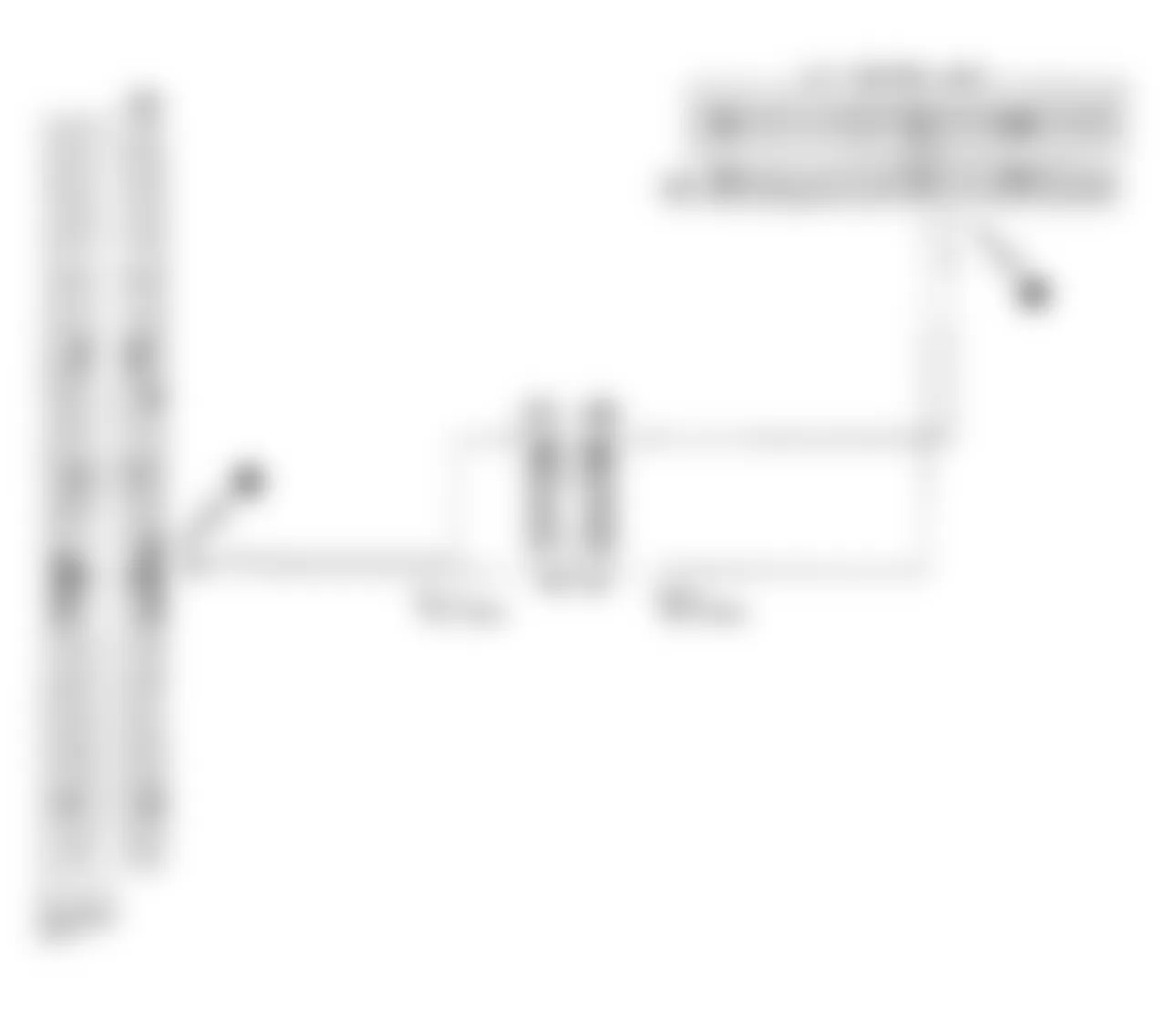

Fig. 42: Infiniti Q45 1990 - Component Locations - Q45 Code 51: Auto Trans Signal Flow Chart