Infiniti Q45 1993 - 1993 ENGINE PERFORMANCE Self-Diagnostics - Q45
Infiniti Q45 1993 - INTRODUCTION
If no faults were found while performing BASIC TESTING, proceed with self-diagnostics. If no fault codes or only pass codes are present after entering self-diagnostics, proceed to TESTS W/O CODES article in the ENGINE PERFORMANCE Section for diagnosis by symptom (i.e., ROUGH IDLE, NO START, etc.).
Infiniti Q45 1993 - SELF-DIAGNOSTIC SYSTEM
Self-diagnostic system is used for diagnosing malfunctions of Electronic Concentrated Control System (ECCS) sensors and actuators. Electronic Control Module (ECM) has 2 available diagnostic modes. Before entering self-diagnostics, perform BASIC TESTING. This prevents wasted diagnostic time and invalid diagnostic results.
Infiniti Q45 1993 - CONSULT TESTER
In addition to self-diagnostic capability, all Infiniti models are equipped with a Data Link Connector (DLC) for use with Nissan's CONSULT Tester (J-38465). On J30 and Q45, DLC is located in left dash side panel.
NOTE: When performing BASIC TESTING, DO NOT erase any diagnostic information stored in ECM memory.
NOTE: CHECK ENGINE light is now referred to as Malfunction Indicator Light (MIL).
Infiniti Q45 1993 - HARD FAILURES
Hard failures cause Malfunction Indicator Light (MIL) to glow and remain on until problem is repaired. If light comes on and remains on (light may flash) during vehicle operation, cause of malfunction must be determined using diagnostic code charts. If a sensor fails, control unit will use a substitute value in its calculations to continue engine operation. In this condition, commonly known as limp- in mode, vehicle runs but driveability will not be optimum.
Infiniti Q45 1993 - INTERMITTENT FAILURES
Intermittent failures may cause Malfunction Indicator Light (MIL) to flicker or glow and go out after intermittent fault goes away. However, corresponding trouble code will be stored in ECM memory. Not all trouble codes will illuminate MIL. If related fault does not reoccur within a certain time frame, related trouble code will be erased from ECM memory. Intermittent failures may be caused by sensor, connector or wiring related problems. See INTERMITTENTS in TESTS W/O CODES article in the ENGINE PERFORMANCE Section.
NOTE: Follow proper diagnostic routine when diagnosing system. See DIAGNOSTIC ROUTINE table.
Infiniti Q45 1993 DIAGNOSTIC ROUTINE
Procedure Order Basic Diagnostic Procedures 1st Entering Diagnostics 2nd Retrieving Trouble Codes 3rd Symptoms (1) 4th Intermittents (1) 5th
(1) Symptoms and intermittents are covered in TESTS W/O CODES article in the ENGINE PERFORMANCE Section.
Infiniti Q45 1993 - MALFUNCTION INDICATOR LIGHT (MIL)
NOTE: Not all trouble codes activate MIL.
All models are equipped with a Malfunction Indicator Light (MIL). As a bulb check, light glows when ignition is turned on and engine is not running.
On California models, MIL glows when a fault is detected with engine running. A corresponding trouble code will set in ECM memory. MIL also glows if ECM or crankshaft position sensor malfunctions.
On Federal models, MIL glows only when ECM or crankshaft position sensor malfunctions with engine running.
Infiniti Q45 1993 - DIAGNOSTIC MODES
Self-diagnostic system can detect ECCS malfunctions and store related trouble codes. Intermittent codes are also stored. All codes are stored until cleared from memory. If an intermittent does not reoccur within 50 ignition key cycles, it will be cleared from memory.
Switching modes is not possible when engine is running. During diagnosis, self-diagnostic system will automatically return to Mode I from Mode II when ignition is turned off.
Infiniti Q45 1993 - Mode I
This is normal operating mode. In this mode, Malfunction Indicator Light (MIL) and Red LED inspection light in ECM stay on when ignition is turned on, engine off (bulb check). If engine is started, MIL and Red LED in ECM should turn off, unless a fault or trouble code is present (California) or if ECM or crankshaft position sensor is malfunctioning (California and Federal).
Infiniti Q45 1993 - Mode II
This is self-diagnostic mode for retrieving fault or trouble codes. See RETRIEVING CODES. With engine running, Mode II can monitor air/fuel mixture feedback control. MIL and Red LED in ECM will flash on (lean) and off (rich) more than 5 times every 10 seconds with engine speed at 2000 RPM when system is in closed loop. MIL and Red LED do not flash (remain on or off) if system is in open loop.
Infiniti Q45 1993 - ECM LOCATION
On J30 and Q45, ECM is located behind right kick panel.
Infiniti Q45 1993 - ENTERING SELF-DIAGNOSTICS
- Turn ignition on, but leave engine off. Using a small screwdriver, turn diagnostic mode selector on ECM fully clockwise. Wait at least 2 seconds, and then turn diagnostic mode selector fully counterclockwise. Mode II self-diagnostics will result, and MIL and Red LED inspection light will flash codes (if present).
- If engine is started at this stage, MIL and Red LED inspection light will display condition of air/fuel mixture, monitored by HO2S sensor, whether system is in closed or open loop.
NOTE: Turn back diagnostic mode selector to fully counterclockwise position whenever vehicle is in use. Switching modes is not possible when engine is running.
Infiniti Q45 1993 - RETRIEVING CODES
Use Mode II to retrieve trouble codes. Read codes using either Malfunction Indicator Light (MIL) or Red LED inspection light on ECM. Trouble codes will flash after selecting Mode II.
Trouble codes are indicated by number of flashes from MIL or Red LED inspection light. For example, 3 long (.6 second) flashes followed by 2 short (.3 second) flashes of MIL or Red LED indicate a Code 32. There will be a .9 second pause between long and short flash groups. There will be a 2.1 second pause between codes.
Infiniti Q45 1993 - CLEARING CODES
NOTE: Ensure all diagnostic codes are accessed from ECM memory before disconnecting battery or switching from Mode II to Mode I.
Infiniti Q45 1993 - Memory Erase
Stored memory can be erased by disconnecting battery or selecting Mode I after Mode II has been accessed.
Infiniti Q45 1993 - FINAL CHECK Final Check For All Code Charts
Unless otherwise instructed in code inspection, perform following FINAL CHECK after each repair is completed.
- Erase Diagnostic Test Mode II (Self-Diagnostic Results) memory. See CLEARING CODES under SELF-DIAGNOSTIC SYSTEM.
- Ensure Code 55 (no malfunction) is displayed in self- diagnostic mode.
- Perform a test drive.
- Perform Diagnostic Test Mode II (Self-Diagnostic Results) again. If results are okay, inspection is complete. If results are not okay, verify ECM pin terminals or harness connector are not damaged.
Infiniti Q45 1993 - SUMMARY
If no hard fault codes (or only pass codes) are present, driveability symptoms exist or intermittent codes exist, proceed to TESTS W/O CODES article in the ENGINE PERFORMANCE Section for diagnosis by symptom (i.e., ROUGH IDLE, NO START, etc.) or intermittent diagnostic procedures.
Infiniti Q45 1993 - TROUBLE CODE DEFINITION
NOTE: When DTC tests indicate to check a component, see indicated component in I - SYS/COMP TESTS article in the ENGINE PERFORMANCE Section. For Diagnostic Trouble Code (DTC) illustration symbol identification, see Fig. 1 . To identify ECM connector terminals, see WIRING DIAGRAMS article in the ENGINE PERFORMANCE Section.
Infiniti Q45 1993 TROUBLE CODE IDENTIFICATION
Code System Affected Probable Cause 11 (1) Crankshaft Position Sensor (2) No Crank Signal 12 Mass Airflow Sensor Circuit Open/Shorted Circuit 13 Engine Coolant Temp. Sensor Open/Shorted Circuit 14 Vehicle Speed Sensor (VSS) No VSS Signal 16 (1) Traction Control System (3) Open/Shorted Circuit 21 (1) Ignition Signal Circuit (2) Open/Shorted Circuit 31 ECM Signals Not Normal 32 (4) EGR Function No EGR Operation 33 HO2S Sensor (Left) Open/Shorted Circuit/High HO2S Signal 34 (1) Knock Sensor Open/Shorted Circuit 35 (4) EGR Temperature Sensor Open/Shorted Circuit 43 Throttle Position Sensor Open/Shorted Circuit 45 (4) Injector Leak Leak At Injectors 46 (1) (Q45 W/TCS) Secondary Throttle Position Sensor Open/Shorted Circuit 51 (4) Injector Circuit Injector Does Not Work 53 HO2S Sensor (Right) Open/Shorted Circuit/High HO2S Signal 54 (1) Automatic Transmission Signal Open Signal Transmission Control Unit 55 (1) No Malfunction Normal Condition
(1) Trouble code will not activate Malfunction Indicator Light (MIL).
(2) If Codes 11 and 21 are present at same time, check items causing a malfunction of crankshaft position sensor circuit first.
(3) See appropriate ANTI-LOCK article in the BRAKES Section.
(4) California models.

Fig. 1: Infiniti Q45 1993 - Component Locations - Identifying DTC Illustration Symbols
Infiniti Q45 1993 - DIAGNOSTIC TROUBLE CODE (DTC) TESTING (Q45)
NOTE: Procedures using Nissan CONSULT Tester (J-38465) will be shown when available. If CONSULT tester is not available, disregard steps using consult tester and use alternate test procedure.
Infiniti Q45 1993 - ECM HARNESS CONNECTOR
NOTE: To locate ECM and identify ECM connector terminals, see Fig. 2 and Fig. 3 .
Fig. 2: Infiniti Q45 1993 - Component Locations - Locating ECM Harness Connector (Q45)

Fig. 3: Infiniti Q45 1993 - Component Locations - ECM Harness Connector Terminals (Q45 Shown)

Infiniti Q45 1993 - DTC 11: CRANKSHAFT POSITION (CKP) SENSOR
- Check Power Supply - Turn ignition off and disconnect CKP sensor harness connector. Turn ignition on. Measure voltage between CKP sensor harness connector terminal "b" (Black/White wire) and ground. See Fig. 4 and Fig. 5 . If battery voltage is present, go to next step. If battery voltage is not present, verify harness continuity between CKP sensor and ECCS relay (Black/White wire), and between CKP sensor and ECM (Black/White wire). Repair harness or connectors as necessary.
Fig. 4: Infiniti Q45 1993 - Component Locations - Locating CKP Sensor Harness Connector
Fig. 5: Infiniti Q45 1993 - Component Locations - DTC 11, Checking Power Supply - Check Input Signal Circuit - Turn ignition off and disconnect ECM harness connector. Verify harness continuity between CKP sensor connector terminal "d" (Green/Black wire) and ECM connector terminals No. 41 and 51 (90 degree signal), and between terminal "c" (Green/Yellow wire) and ECM terminal No. 42 (one degree signal). See Fig. 2 , Fig. 3 and Fig. 6 . If continuity is present, go to next step. If continuity is not present, repair harness or connectors as necessary.
- Check Component - Inspect CKP sensor. See I - SYS/COMP TESTS article in the ENGINE PERFORMANCE Section. Replace CKP sensor if necessary and perform FINAL CHECK.


Fig. 6: Infiniti Q45 1993 - Component Locations - DTC 11, Checking Input Signal Circuit

Infiniti Q45 1993 - DTC 12: MASS AIRFLOW (MAF) SENSOR
- Check Power Supply - Turn ignition off and disconnect MAF sensor harness connector. Turn ignition on. Measure voltage between MAF sensor harness connector terminal "a" (Black/White wire) and ground. See Fig. 7 and Fig. 8 . If battery voltage is present, go to next step. If battery voltage is not present, verify harness continuity between MAF sensor and ECM, and MAF sensor and ECCS relay. Repair harness or connectors as necessary.
Fig. 7: Infiniti Q45 1993 - Component Locations - Locating MAF Sensor Harness Connector
Fig. 8: Infiniti Q45 1993 - Component Locations - DTC 12, Checking Power Supply - Check Ground Circuit - Turn ignition off and disconnect ECM harness connector. Verify harness continuity between MAF sensor connector terminal "b" (Black wire) and ECM connector terminal No. 26. See Fig. 2 , Fig. 3 and Fig. 9 . If continuity is present, go to next step. If continuity is not present, repair harness or connectors as necessary.
- Check Input Signal Circuit - Turn ignition off and disconnect ECM harness connector. Check continuity between MAF sensor connector terminal "c" (White wire) and ECM terminal No. 27. See Fig. 2 , Fig. 3 and Fig. 10 . If continuity is present, go to next step. If continuity is not present, repair harness or connectors as necessary.
- Check Component - Inspect MAF sensor. See I - SYS/COMP TESTS article in the ENGINE PERFORMANCE Section. Replace MAF sensor if necessary and perform FINAL CHECK.


Fig. 9: Infiniti Q45 1993 - Component Locations - DTC 12, Checking Ground Circuit

Fig. 10: Infiniti Q45 1993 - Component Locations - DTC 12, Checking Input Signal Circuit

Infiniti Q45 1993 - DTC 13: ENGINE COOLANT TEMPERATURE (ECT) SENSOR
- Check Power Supply I - Turn ignition off and disconnect EFI sub-harness connector No. 2. Turn ignition on. Measure voltage between EFI sub-harness connector No. 2 terminal "d" (Yellow/Black wire) and ground. See Fig. 11 and Fig. 12 . If voltage is approximately 5 volts, go to next step. If voltage is not as specified, repair harness or connectors as necessary.
Fig. 11: Infiniti Q45 1993 - Component Locations - Locating EFI Sub-Harness Connector No. 2
Fig. 12: Infiniti Q45 1993 - Component Locations - DTC 13, Checking Power Supply I - Check Ground Circuit I - Turn ignition off. Check EFI sub-harness No. 2 continuity between terminal "a" (Black/Yellow wire, with TCS; Black wire, without TCS) and engine ground. See Fig. 13 . If continuity is present, go to next step. If continuity is not present, repair harness or connectors as necessary.
Fig. 13: Infiniti Q45 1993 - Component Locations - DTC 13, Checking Ground Circuit I - Check Power Supply II - Connect EFI sub-harness No. 2 connector. Disconnect ECT harness connector. Turn ignition on. Measure voltage between ECT harness connector terminal "h" (Yellow/Black wire) and ground. See Fig. 14 and Fig. 15 . If voltage is approximately 5 volts, go to next step. If voltage is not as specified, repair harness or connectors as necessary.
- Check Ground Circuit II - Turn ignition off. Check ECT harness continuity between terminal "g" (Black wire) and engine ground. See Fig. 16 . If continuity is present, go to next step. If continuity is not present, repair harness or connectors as necessary.
- Check Component - Inspect ECT sensor. See I - SYS/COMP TESTS article in the ENGINE PERFORMANCE Section. Replace ECT sensor if necessary and perform FINAL CHECK.


Fig. 14: Infiniti Q45 1993 - Component Locations - Locating ECT Sensor

Fig. 15: Infiniti Q45 1993 - Component Locations - DTC 13, Checking Power Supply II

Fig. 16: Infiniti Q45 1993 - Component Locations - DTC 13, Checking Ground Circuit II

Infiniti Q45 1993 - DTC 14: VEHICLE SPEED SENSOR (VSS)
- Check Speedometer Operation - Ensure speedometer operates properly. If speedometer operates properly, go to next step. VSS is located on transmission rear extension. If speedometer does not operate properly, remove VSS from transmission. Turn speedometer pinion quickly. Measure voltage between terminals "a" and "b" at VSS connector. If voltage is approximately .5 volt and alternating, go to next step. If voltage is not as specified, replace VSS.
- Check Input Signal Circuit - Turn ignition off and disconnect ECM harness connector and combination meter harness connector. Check harness continuity between ECM terminal No. 53 and combination meter terminal "l" (Yellow/Green wire). See Fig. 2 , Fig. 3 and Fig. 17 . If continuity is present, verify ECM terminals are not damaged and connector is properly connected. Perform FINAL CHECK. If continuity is not present, repair harness or connectors as necessary and perform FINAL CHECK.
Fig. 17: Infiniti Q45 1993 - Component Locations - DTC 14, Checking Input Signal Circuit

Infiniti Q45 1993 - DTC 16: TRACTION CONTROL SYSTEM (TCS) SIGNAL
- Check Input Signal Circuit - Turn ignition off. Disconnect ECM harness connector and Traction Control Module (TCM) 20-pin harness connector. Check harness continuity between ECM terminal No. 36 and TCM terminal No. 7 (Red/Green wire). See Fig. 18 and Fig. 19 . If continuity is present, go to next step. If continuity is not present, verify harness and connector continuity between ECM and TCM. Repair harness or connectors as necessary.
- Check Component - Inspect TCS function. See TRACTION CONTROL SYSTEM article in the BRAKES section. Replace TCS component(s) if necessary and perform FINAL CHECK.
Fig. 18: Infiniti Q45 1993 - Component Locations - Locating TCM Harness Connector

Fig. 19: Infiniti Q45 1993 - Component Locations - DTC Checking Input Signal Circuit

Infiniti Q45 1993 - DTC 21: IGNITION SIGNAL
- When either cylinders No. 1, 3, 5 and 7 or cylinders No. 2, 4, 6 and 8 are all not operating, go to next step. If there is a different malfunction, go to step 3) or to step 4).
- Check Ground Circuit - Turn ignition off. Disconnect Power Transistor Unit (PTU) harness connectors. Verify harness continuity between PTU harness connector terminals "f" and "l" (Black wire) and engine ground. See Fig. 20 -Fig. 27 . If continuity is present, go to step 4). If continuity is not present, repair harness or connectors as necessary and perform FINAL CHECK .
Fig. 20: Infiniti Q45 1993 - Component Locations - Locating Ignition Coil Relay
Fig. 21: Infiniti Q45 1993 - Component Locations - Locating EFI Sub-Harness Connector No. 4
Fig. 22: Infiniti Q45 1993 - Component Locations - Locating EFI Sub-Harness Connector No. 5
Fig. 23: Infiniti Q45 1993 - Component Locations - Locating PTU Harness Connector (Left Side)
Fig. 24: Infiniti Q45 1993 - Component Locations - Locating PTU Harness Connector (Right Side)
Fig. 25: Infiniti Q45 1993 - Component Locations - DTC 21, Checking Ground Circuit
Fig. 26: Infiniti Q45 1993 - Component Locations - Locating Ignition Coils (Right Side)
Fig. 27: Infiniti Q45 1993 - Component Locations - Locating Ignition Coils (Left Side) - Search For Malfunctioning Circuit Using CONSULT - Turn ignition off and connect CONSULT. Perform POWER BALANCE in ACTIVE TEST mode with CONSULT. Search for circuit which does not produce a momentary engine speed drop.
- Check Output Signal Circuit - Turn ignition off. Disconnect ECM harness connector and PTU harness connector. Verify harness continuity between ECM harness connector terminals and PTU harness connector terminals as follows:
- ECM terminal No. 1 and PTU terminal "b" (Green wire).
- ECM terminal No. 2 and PTU terminal "j" (Yellow wire).
- ECM terminal No. 3 and PTU terminal "d" (Green/White wire).
- ECM terminal No. 11 and PTU terminal "a" (Yellow/White wire).
- ECM terminal No. 12 and PTU terminal "k" (Green/Black wire).
- ECM terminal No. 13 and PTU terminal "e" (Yellow/Black wire).
- ECM terminal No. 14 and PTU terminal "g" (Green/Red wire).
- ECM terminal No. 15 and PTU terminal "h" (Yellow/Red wire).
See Fig. 28 . If continuity is present, go to next step. If continuity is not present, verify harness continuity between ECM connector and PTU connector. Repair harness or connectors as necessary.
- Check Component - Inspect power transistor unit. See I - SYS/COMP TESTS article in the ENGINE PERFORMANCE Section. Replace power transistor unit if necessary and perform FINAL CHECK .


Fig. 28: Infiniti Q45 1993 - Component Locations - DTC 21, Checking Output Signal Circuit

Infiniti Q45 1993 - DTC 31: ECM
Turn ignition on. Erase Diagnostic Test Mode II (Self-Diagnostic Results) memory. Perform Diagnostic Test Mode II (Self-Diagnostic Results). If ECM displays DTC 31 again, replace ECM.
Infiniti Q45 1993 - DTC 32: EGR FUNCTION (CALIF.)
- Check Vacuum Source To EGR Valve - Start engine and bring to operating temperature. Perform Diagnostic Test Mode II (Self-Diagnostic Results) ensuring DTC 11 and DTC 12 are not displayed. With engine speed at about 2000 RPM, disconnect vacuum hose to EGR valve. See Fig. 29 and Fig. 30 . If vacuum is not present, go to next step. If vacuum is present, inspect EGR valve and EGRC Backpressure Transducer valve. See I - SYS/COMP TESTS article in the ENGINE PERFORMANCE Section. Replace EGR valve and/or EGRC Backpressure Transducer valve if necessary and perform FINAL CHECK .
Fig. 30: Infiniti Q45 1993 - Component Locations - DTC 32, Checking Vacuum Source To EGR Valve - Check Control Function - If vacuum is not present, with engine running, measure voltage between ECM terminal No. 102 (Blue/Red wire) and ground. At idle, voltage should be approximately zero volts. At 2000 RPM, voltage should be battery voltage. See Fig. 31 . If voltage measured is not as specified, go to step 4). If voltage is as specified, inspect vacuum hose for clogging, cracks or proper connection. Repair or replace vacuum hose as necessary.
Fig. 31: Infiniti Q45 1993 - Component Locations - DTC 32, Checking Control Function - Check Control Function Using CONSULT - If vacuum is not present, turn ignition off. Connect CONSULT and turn ignition on. Perform EGRC SOL/V CIRCUIT in FUNCTION TEST mode. Another method is to use CONSULT to turn EGRC solenoid valve ON and OFF in ACTIVE TEST mode and check for operating sounds. If EGRC solenoid valve is okay, inspect vacuum hose for clogging, cracks or proper connection. Repair or replace vacuum hose as necessary.
- Check Output Signal Circuit - Turn engine off and disconnect ECM harness connector. Disconnect EGRC solenoid valve harness connector. Verify harness continuity between ECM terminal No. 102 (Blue/Red wire) and ground, and between EGRC solenoid valve harness connector terminal "b" (Blue/Red wire) and ground. See Fig. 32 . If continuity does not exist, go to next step. If there is continuity, repair harness or connectors between ECM and EGRC solenoid valve, as necessary.
Fig. 32: Infiniti Q45 1993 - Component Locations - DTC 32, Checking Output Signal Circuit - Check Component - Inspect EGRC solenoid valve. See I - SYS/COMP TESTS article in the ENGINE PERFORMANCE Section. Replace EGR control solenoid valve if necessary. If EGRC solenoid valve is okay, inspect EGR temperature sensor resistance. See I - SYS/COMP TESTS article in the ENGINE PERFORMANCE Section. Replace EGR temperature sensor if necessary and perform FINAL CHECK .


Infiniti Q45 1993 - DTC 33 (LEFT) & 53: (RIGHT) HEATED OXYGEN SENSOR (HO2S)
- Check Input Signal Circuit - Turn ignition off and disconnect HO2S harness connector and ECM harness connector. Verify harness continuity between ECM connector terminals No. 29 (right), No. 55 (left) and HO2S connector terminal "b" (White wire). See Fig. 33 , Fig. 34 and Fig. 35 . If continuity is present, go to next step. If continuity is not present, repair harness or connectors as necessary.
Fig. 33: Infiniti Q45 1993 - Component Locations - Locating Left HO2S Harness Connector
Fig. 34: Infiniti Q45 1993 - Component Locations - Locating Right HO2S Harness Connector
Fig. 35: Infiniti Q45 1993 - Component Locations - DTC 33 & 53, Checking Input Signal Circuit - Check Voltage - Connect HO2S harness connector and ECM harness connector. Bring engine to operating temperature and hold speed at approximately 2000 RPM. Using an analog voltmeter, measure voltage between ECM terminals No. 29 and 55 (White wire) and ground. See Fig. 36 . If voltage measured is approximately .3 volt and there are no voltage fluctuations, replace HO2S. If voltage fluctuates between approximately .2-.9 volt, HO2S is okay. Perform FINAL CHECK .
Fig. 36: Infiniti Q45 1993 - Component Locations - DTC 33 & 53, Checking Voltage - Check Voltage Using CONSULT - Turn ignition off. Connect CONSULT, HO2S harness connector and ECM harness connector. Start engine, bring to operating temperature and hold speed at approximately 2000 RPM. Select DATA MONITOR mode with CONSULT. Touch RECORD. Check O2 SEN (-R) voltage. If voltage displayed is approximately .3 volt and there are no voltage fluctuations, replace HO2S. If voltage displayed fluctuates between approximately .2-.9 volt, HO2S is okay. Perform FINAL CHECK .


Infiniti Q45 1993 - DTC 34: KNOCK SENSOR
- Check Input Signal Circuit I - Turn ignition off. Disconnect ECM harness connector and EFI sub-harness No. 2 connector. Verify harness continuity between EFI sub-harness No. 2 connector terminal "c" (White wire) and ECM terminal No. 23, and connector terminal "f" (White wire) and ECM terminal No. 24. If continuity is present, go to next step. If continuity is not present, repair harness or connectors as necessary. See Fig. 2 , Fig. 3 , Fig. 37 and Fig. 38 .
Fig. 37: Infiniti Q45 1993 - Component Locations - Locating EFI Sub-Harness No. 2 Connector
Fig. 38: Infiniti Q45 1993 - Component Locations - DTC 34, Checking Input Signal Circuit I - Check Input Signal Circuit II - Disconnect knock sensor (left and right) harness connectors. Verify harness continuity between EFI sub-harness terminal "i" and left knock sensor harness connector terminal "g" (White wire) and between EFI sub-harness terminal "l" and right knock sensor harness connector terminal "h" (White wire). If continuity is present, go to next step. If continuity is not present, repair harness or connectors as necessary. See Fig. 39 and Fig. 40 .
- Check Component - Inspect knock sensor. See I - SYS/COMP TESTS article in the ENGINE PERFORMANCE Section. Replace knock sensor if necessary and perform FINAL CHECK .


Fig. 39: Infiniti Q45 1993 - Component Locations - Locating Knock Sensors

Fig. 40: Infiniti Q45 1993 - Component Locations - DTC 34, Checking Input Signal Circuit II
Infiniti Q45 1993 - DTC 35: EGR TEMPERATURE SENSOR (CALIF.)
- Check Power Supply - Turn ignition off and disconnect EGR temperature sensor harness connector. Turn ignition on. Measure voltage between EGR temperature sensor connector terminal "a" (Orange/Black wire) and ground. If voltage is approximately 5 volts, go to next step. If voltage is not as specified, repair harness or connectors as necessary. See Fig. 41 and Fig. 42 .
Fig. 41: Infiniti Q45 1993 - Component Locations - Locating EGR Temperature Sensor Connector
Fig. 42: Infiniti Q45 1993 - Component Locations - DTC 35, Checking Power Supply - Check Ground Circuit - Turn ignition off. Verify harness continuity between EGR temperature sensor connector terminal "b" (Black/Yellow wire, with TCS; Black wire, without TCS) and engine ground. See Fig. 43 . If continuity is present, go to next step. If continuity is not present, repair harness or connectors as necessary.
- Check Component - Inspect EGR temperature sensor. See I - SYS/COMP TESTS article in the ENGINE PERFORMANCE Section. Replace EGR temperature sensor if necessary and perform FINAL CHECK .


Fig. 43: Infiniti Q45 1993 - Component Locations - DTC 35, Checking Ground Circuit

Infiniti Q45 1993 - DTC 43: THROTTLE POSITION SENSOR (TPS)
- Check Power Supply - Turn ignition off and disconnect TPS harness connector. Turn ignition on. Measure voltage between TPS connector terminal "c" (Red/White wire) and ground. See Fig. 44 , Fig. 45 and Fig. 46 . If voltage is approximately 5 volts, go to next step. If voltage is not as specified, repair harness or connectors as necessary.
Fig. 44: Infiniti Q45 1993 - Component Locations - Locating TPS Harness Connector (Without TCS)
Fig. 45: Infiniti Q45 1993 - Component Locations - Locating TPS Harness Connector (With TCS)
Fig. 46: Infiniti Q45 1993 - Component Locations - DTC 43, Checking Power Supply - Check Ground Circuit - Turn ignition off. Verify harness continuity between TPS connector terminal "a" (Black/Yellow wire) and engine ground. See Fig. 47 . If continuity is present, go to next step. If continuity is not present, repair harness or connectors as necessary.
- Check Input Signal Circuit - Disconnect ECM harness connector. See Fig. 2 . Verify harness continuity between ECM connector terminal No. 38 and TPS connector terminal "b" (White wire). See Fig. 3 and Fig. 48 . If continuity is present, go to next step. If continuity is not present, repair harness or connectors as necessary.
- Check Component - Inspect TPS. See I - SYS/COMP TESTS article in the ENGINE PERFORMANCE Section. Replace TPS if necessary and perform FINAL CHECK .


Fig. 47: Infiniti Q45 1993 - Component Locations - DTC 43, Checking Ground Circuit

Fig. 48: Infiniti Q45 1993 - Component Locations - DTC 43, Checking Input Signal Circuit

Infiniti Q45 1993 - DTC 45: INJECTOR LEAK (CALIF.)
- Clear Self-Learning Data - Clear self-learning data. Start engine and bring to operating temperature. Stop engine and disconnect Mass Airflow (MAF) sensor connector. Start engine and run for at least 30 seconds at 2000 RPM. See Fig. 49 . Stop engine and connect MAF sensor connector. Ensure DTC 12 is displayed in Diagnostic Test Mode II. Erase self-diagnosis memory. Ensure DTC 55 is displayed in Diagnostic Test Mode II. See ENTERING SELF-DIAGNOSTICS.
- Clear Self-Learning Data Using CONSULT - Select SELF-LEARNING CONT in ACTIVE TEST mode with CONSULT. Clear self-learning control coefficient by touching CLEAR.
Fig. 49: Infiniti Q45 1993 - Component Locations - DTC 45, Clearing Self-Learning Data - Perform Diagnostic Test Mode II (Self-Diagnostic Results) - If DTC does not return, inspection is completed. If DTC 45 displays, relieve fuel pressure and remove injector assembly. See N - REMOVE/INSTALL/OHAUL article in the ENGINE PERFORMANCE Section. Do not remove fuel hose or injectors from injector gallery. Turn ignition on. Ensure fuel does not drip from injector(s). Replace any injector(s) that drip fuel. Perform FINAL CHECK .

Infiniti Q45 1993 - DTC 46: SECONDARY THROTTLE POSITION SENSOR (WITH TCS)
- Check Power Supply - Turn ignition off and disconnect Secondary Throttle Position (TP) sensor harness connector. Turn ignition on. Measure voltage between TP sensor connector terminal "c" (Red/White wire) and ground. See Fig. 50 and Fig. 51 . If voltage is approximately 5 volts, go to next step. If voltage is not as specified, verify harness continuity between TP and ECM connectors. Repair harness or connectors as necessary.
Fig. 50: Infiniti Q45 1993 - Component Locations - Locating Secondary Throttle Position Sensor
Fig. 51: Infiniti Q45 1993 - Component Locations - DTC 46, Checking Power Supply - Check Ground Circuit - Turn ignition off. Verify harness continuity between TP sensor connector terminal "a" (Black/Yellow wire) and ground. If continuity is present, go to next step. See Fig. 50 and Fig. 52 . If continuity is not present, verify harness continuity between TP sensor and ECM connectors. Repair harness or connectors as necessary.
Fig. 52: Infiniti Q45 1993 - Component Locations - DTC 46, Checking Ground Circuit - Check Input Signal Circuit I - Disconnect ECM harness connector and TCM harness connector. Verify harness continuity between ECM connector terminal No. 37 (Purple/White wire) and TCM connector terminal No. 4 (Purple/White wire). If continuity is present, go to next step. If continuity is not present, verify harness continuity between ECM connector and TCM connector. Repair harness or connectors as necessary. See Fig. 2 , Fig. 3 , Fig. 53 and Fig. 54 .
Fig. 53: Infiniti Q45 1993 - Component Locations - Locating TCM
Fig. 54: Infiniti Q45 1993 - Component Locations - DTC 46, Checking Input Signal Circuit I - Check Input Signal Circuit II - Verify harness continuity between TCM connector terminal No. 3 (White wire) and TP sensor connector terminal "b" (White wire). If continuity is present, go to next step. If continuity is not present, verify harness continuity between TCM connector and TP sensor connector. Repair harness or connectors as necessary. See Fig. 55 .
Fig. 55: Infiniti Q45 1993 - Component Locations - DTC 46, Checking Input Signal Circuit II - Check Component - Inspect secondary throttle position sensor. See I - SYS/COMP TESTS article in the ENGINE PERFORMANCE Section. Replace secondary throttle position sensor if necessary. If secondary throttle position sensor is okay, check Traction Control Module (TCM) operation. See TRACTION CONTROL SYSTEM article in the BRAKES section. Replace TCM if necessary. Check ECM pin terminals for damage or improper harness connection and perform FINAL CHECK .


Infiniti Q45 1993 - DTC 51: INJECTOR (CALIF.)
- Search For Malfunctioning Circuit - Using a listening device, search for circuit which does not produce injector operating sound at idle. See Fig. 56 .
- Search For Malfunctioning Circuit Using CONSULT - Perform POWER BALANCE in ACTIVE TEST mode. Search for circuit which does not produce a momentary engine speed drop.
Fig. 56: Infiniti Q45 1993 - Component Locations - DTC 51, Checking For Injector Operating SoundNOTE: When either cylinders No. 1, 3, 5 and 7 or cylinders No. 2, 4, 6 and 8 are all not operating, go to next step. If there is a different malfunction, go to step 4). - Check Power Supply I - Turn ignition off. Disconnect EFI sub-harness No. 1, 4-pin connector. Measure voltage between EFI sub-harness No. 1 connector terminals "b" (Red wire) and ground, and "d" (Red wire) and ground. See Fig. 57 and Fig. 58 . If battery voltage is present, go to next step. If battery voltage is not present, verify harness continuity between EFI sub-harness No. 1 connector and Blue EFI harness connector. If continuity is present, go to next step. If continuity is not present, repair harness or connectors as necessary.
Fig. 57: Infiniti Q45 1993 - Component Locations - Locating EFI Sub-Harness No. 1 Connector
Fig. 58: Infiniti Q45 1993 - Component Locations - DTC 51, Checking Power Supply I - Check Power Supply II - Turn ignition off and disconnect EFI sub-harness No. 1, 4-pin and 8-pin connectors. See Fig. 57 . Verify harness continuity between 4-pin and 8-pin connector (injector side) terminals as follows: Infiniti Q45 1993 - Component Locations -
- Terminal "e" (Red wire) and terminal "i" (Blue wire).
- Terminal "e" (Red wire) and terminal "j" (Blue/Black wire).
- Terminal "e" (Red wire) and terminal "n" (Red/Black wire).
- Terminal "e" (Red wire) and terminal "o" (Red/Yellow wire).
- Terminal "g" (Red wire) and terminal "k" (Blue/Yellow wire).
- Terminal "g" (Red wire) and terminal "l" (Blue/Red wire).
- Terminal "g" (Red wire) and terminal "m" (Red wire).
- Terminal "g" (Red wire) and terminal "p" (Red/Green wire).
See Fig. 59 . If continuity is present, go to step 6). If continuity is not present, disconnect each injector harness connector. Verify continuity between following terminals: Infiniti Q45 1993 - Component Locations -
- Terminals "q" and "e".
- Terminals "q" and "g".
- Terminals "i" and "r".
- Terminals "j" and "r".
- Terminals "k" and "r".
- Terminals "l" and "r".
- Terminals "m" and "r".
- Terminals "n" and "r".
- Terminals "o" and "r".
- Terminals "p" and "r".
See Fig. 60 and Fig. 61 . If continuity is present, go to next step. If continuity is not present, repair harness or connectors as necessary.
- Check Component - Inspect each injector. See I - SYS/COMP TESTS article in the ENGINE PERFORMANCE Section. Replace if necessary and perform FINAL CHECK .
- Check Output Signal Circuit - Disconnect ECM harness connector. Verify harness continuity between following ECM connector terminals and EFI 8-pin connector terminals:
- EFI terminal "s" and ECM terminal No. 113 (Blue/Green wire).
- EFI terminal "t" and ECM terminal No. 105 (Blue/Yellow wire).
- EFI terminal "u" and ECM terminal No. 103 (Blue/Black wire).
- EFI terminal "v" and ECM terminal No. 101 (Blue wire).
- EFI terminal "w" and ECM terminal No. 106 (Red/Green wire).
- EFI terminal "x" and ECM terminal No. 114 (Red/Yellow wire).
- EFI terminal "y" and ECM terminal No. 112 (Red/Black wire).
- EFI terminal "z" and ECM terminal No. 110 (Red wire).
See Fig. 62 . If continuity is not present, repair harness or connectors as necessary. If continuity is present, inspect ECM pin terminals for damage or check for bad connection of ECM harness connector. Perform FINAL CHECK .


Fig. 59: Infiniti Q45 1993 - Component Locations - DTC 51, Checking Power Supply II

Fig. 60: Infiniti Q45 1993 - Component Locations - Locating Injector Harness Connectors

Fig. 61: Infiniti Q45 1993 - Component Locations - DTC 51, Checking Injector Harness Continuity
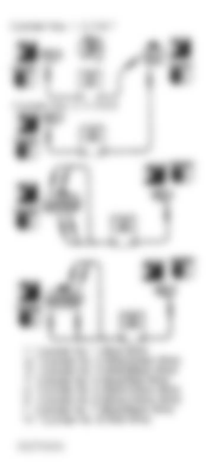
Fig. 62: Infiniti Q45 1993 - Component Locations - DTC 51, Checking Output Signal Circuit

Infiniti Q45 1993 - DTC 54: AUTOMATIC TRANSMISSION (A/T) CONTROL Check Input Signal Circuit
Turn ignition off. Disconnect ECM harness connector and A/T control unit harness connector. Verify harness continuity between ECM connector terminal No. 34 and A/T control unit connector terminal No. 10 (Blue/Red wire). Verify harness continuity between ECM connector terminal No. 35 and A/T control unit connector terminal No. 11 (Blue wire). See Fig. 63 and Fig. 64 . If continuity is present, perform FINAL CHECK . If continuity is not present, check harness and connectors between ECM and A/T control unit. Repair harness or connectors as necessary and perform FINAL CHECK .
Fig. 63: Infiniti Q45 1993 - Component Locations - Locating A/T Control Unit Connector

Fig. 64: Infiniti Q45 1993 - Component Locations - DTC 54, Checking Input Signal Circuit