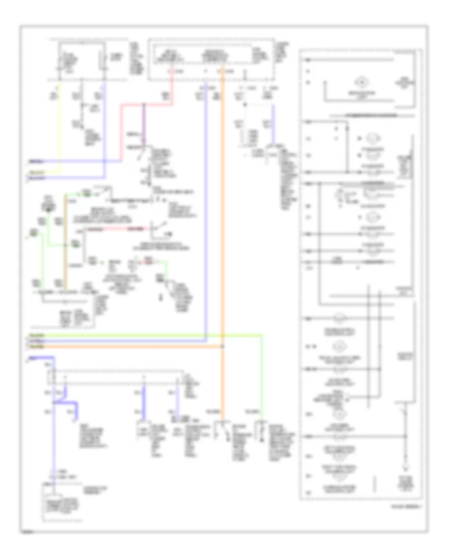
AUTOMOTIVE ELECTRICIANS PORTAL

INSTRUMENT CLUSTER – Acura Integra GS-R 1997 – SYSTEM WIRING DIAGRAMS

INSTRUMENT CLUSTER

Instrument Cluster Wiring Diagram (1 of 2) for Acura Integra GS-R 1997

Instrument Cluster Wiring Diagram (1 of 2) for Acura Integra GS-R 1997 https://portal-diagnostov.com/license.html
https://portal-diagnostov.com/license.html Automotive Electricians Portal FZCO Automotive Electricians Portal FZCO
Download PDF file

List of elements for Instrument Cluster Wiring Diagram (1 of 2) for Acura Integra GS-R 1997:

  • (1995 only)
  • (1995)
  • (1996, 1997)
  • (1997) (1996)
  • 1994 vftc c
  • A/t gear position switch (below center console, at base of shift lever)
  • A10
  • A11
  • A12
  • A13
  • A15
  • A17
  • A19
  • Abs indicator light
  • Anti-lock brakes system
  • B10
  • B11
  • B13
  • B14
  • B15
  • B16
  • Bat. input
  • Brake system indicator light
  • C10
  • C216
  • C439
  • C551
  • C557
  • C558
  • C559
  • C560
  • Cruise control system
  • D11
  • D12
  • D13
  • Drive ckt.
  • Drive input
  • Engine controls system
  • Engine coolant temperature (ect) gauge
  • Exterior lights system
  • From right turn indi- cator (diagram 2 of 2)
  • Fuel gauge
  • Fuse 15 back-up light e-at unit 10a
  • Fuse 24 acg ig 15a (except 1995 gs-r) 20a (1995 gs-r)
  • Fuse 32 back-up 7.5a
  • G202 (behind left side of i/p, above kick panel)
  • Gauge assembly
  • Gnd.
  • Headlights system
  • Hot at all times
  • Hot in on or start
  • Ign. input
  • Illum. cancel
  • Ind. ctrl
  • Interior lights system
  • J/c c556 (under left side of dash)
  • Light ctrl.
  • Low fuel indicator light
  • Low oil pressure indicator light
  • Maintenance reminder light
  • Maintenance reminder unit (on rear of dash- board lower cover)
  • Malfunction indicator light (mil)
  • Odometer/ tripmeter stepper motor
  • Only
  • P/n input
  • Pnk
  • Red
  • Reverse input
  • Seat belt reminder indicator light
  • Shift inter- lock system
  • Speedometer
  • Srs fuse block (under left side of dashboard)
  • Tach. drive ckt.
  • Tachometer
  • To door open indicator (diagram 2 of 2)
  • Transmission control module (tcm) (behind left hand kick panel)
  • Under- dash fuse/ relay box
  • Under- dash fuse/relay box
  • Under-hood fuse/relay box
  • Vehicle speed sensor (vss) (on top rear of trans.)
  • Vss input
  • Vss output

Instrument Cluster Wiring Diagram (2 of 2) for Acura Integra GS-R 1997

Instrument Cluster Wiring Diagram (2 of 2) for Acura Integra GS-R 1997 https://portal-diagnostov.com/license.html
https://portal-diagnostov.com/license.html Automotive Electricians Portal FZCO Automotive Electricians Portal FZCO
Get access to all wiring diagrams of the carDownload PDF file

List of elements for Instrument Cluster Wiring Diagram (2 of 2) for Acura Integra GS-R 1997:

  • (1995 only)
  • (1995)
  • (1995) (1996, 1997)
  • (1996)
  • (1996, 1997)
  • (1997 only)
  • (1997)
  • (diagram 1 of 2)
  • (not used)
  • 1 indicator
  • 2 indicator
  • A/t gear position indicator
  • A9 a5
  • Abs control unit (sedan: on right side of luggage compt.; hatch- back: behind right quarter panel trim)
  • Alter- nator
  • Anti- lock brakes system
  • B10
  • B11
  • B13
  • B14
  • B15
  • Brake bulb check ckt.
  • Brake fluid level switch (closed with low fluid level) (on brake fluid reservoir cap)
  • Brake ind. out.
  • C10
  • C119
  • C309
  • C310
  • C440
  • C446
  • C504
  • C551
  • C703
  • Canada
  • Charging system indicator light
  • Chg
  • Cruise control indicator light
  • Cruise control unit (under left side of dash)
  • Cruise ctrl dim- ming ckt
  • D3 indicator
  • D4 indicator
  • Daytime running lights control unit (behind left side kick panel)
  • Dimming circuit
  • Dimming ckt.
  • Distributor assembly
  • Door open indicator light
  • Driver's seat belt switch (closed with seat belt) unbuckled)
  • Engine coolant temperature (ect) gauge sending unit (right side of engine, in cylinder head)
  • Engine oil pressure ind. flasher ckt.
  • Engine oil pressure switch (opens above 4.3 psi) (near oil filter)
  • Engine speed output
  • From maintenance reminder light b
  • Fuel gauge send- ing unit
  • Fuel tank unit (in fuel tank, under access cover)
  • G100 (left front corner of engine compt.)
  • G300 (under driver's seat)
  • Gauge assembly
  • High beam indicator light
  • Ignition control module (icm)
  • Illum (3 bulbs)
  • Inte- grated control unit
  • J/c c418 (behind left kick panel)
  • Key-in seat belt reminder ckt.
  • Left turn signal indicator light
  • N indicator
  • P indicator
  • P.b.
  • Park brake switch (on base of park brake lever)
  • Parking brake switch (on base of park brake lever)
  • R indicator
  • Right turn signal indicator light
  • Rpm input
  • Srs indicator ckt.
  • Srs indicator light
  • Sw. in.
  • Test tachometer connector (left rear corner of engine compt.)
  • Therm- istor
  • To fuel gauge (diagram 1 of 2)
  • Transmission control module (tcm) (behind left hand kick panel)
  • Trunk lid/hatch open indicator light
  • Under dash- fuse/ relay box
  • Under- dash fuse/ relay box
  • Usa