INSTRUMENT CLUSTER
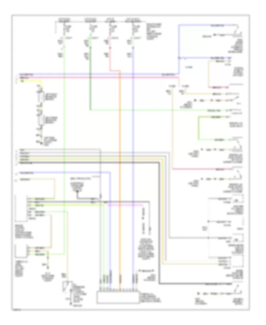
Instrument Cluster Wiring Diagram (1 of 2) for BMW M Coupe 1999

List of elements for Instrument Cluster Wiring Diagram (1 of 2) for BMW M Coupe 1999:
Instrument Cluster Wiring Diagram (2 of 2) for BMW M Coupe 1999
List of elements for Instrument Cluster Wiring Diagram (2 of 2) for BMW M Coupe 1999:
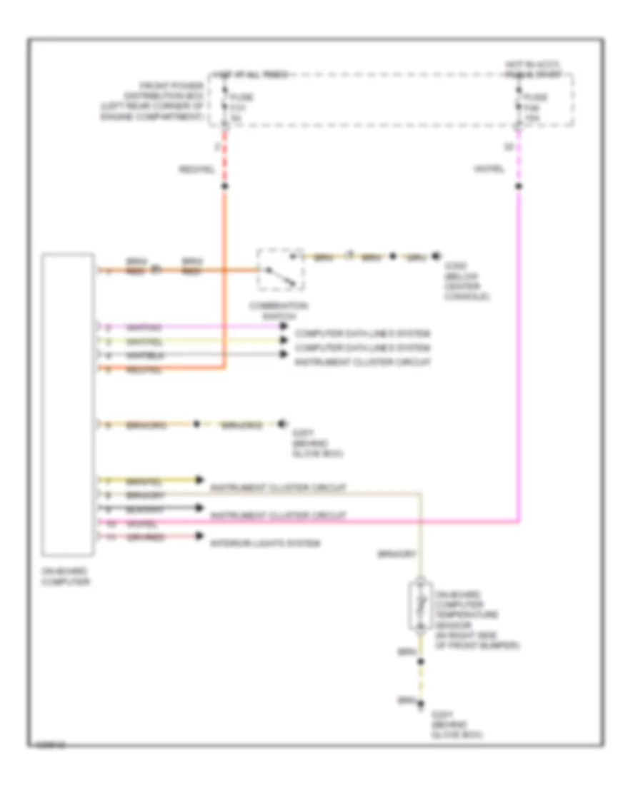
On-Board Computer Wiring Diagram for BMW M Coupe 1999
List of elements for On-Board Computer Wiring Diagram for BMW M Coupe 1999: