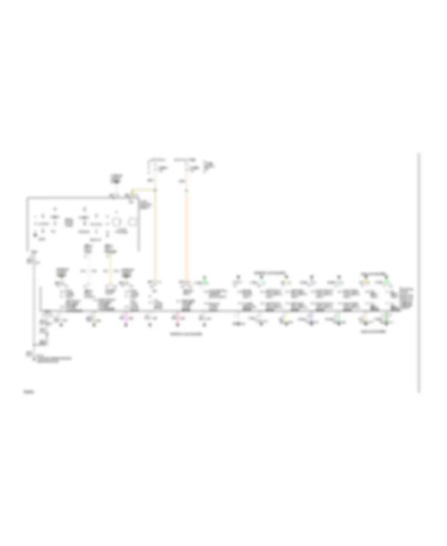
INSTRUMENT CLUSTER
Instrument Cluster Wiring Diagram, Base for Buick LeSabre Custom 1994

List of elements for Instrument Cluster Wiring Diagram, Base for Buick LeSabre Custom 1994:
Instrument Cluster Wiring Diagram, Gauges for Buick LeSabre Custom 1994
List of elements for Instrument Cluster Wiring Diagram, Gauges for Buick LeSabre Custom 1994:
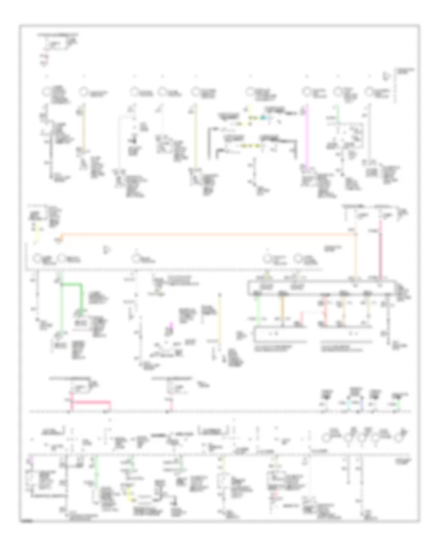
Lamp Monitor Wiring Diagram for Buick LeSabre Custom 1994
List of elements for Lamp Monitor Wiring Diagram for Buick LeSabre Custom 1994: