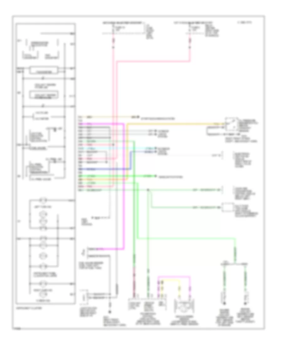
INSTRUMENT CLUSTER
Instrument Cluster Wiring Diagram, Base Cluster, U23 for Buick Park Avenue Ultra 1995

List of elements for Instrument Cluster Wiring Diagram, Base Cluster, U23 for Buick Park Avenue Ultra 1995:
- (right front of eng compt, above right horn)
- (right front of eng, under ignition control module)
- A10
- A11
- Accy
- Air bag ind.
- Anti-lock brakes system
- Anti-theft system
- Antilock ind.
- B10
- B11
- Brake fluid level switch (master cylinder reservoir)
- Brake ind.
- Bulb test
- C 1995 vftc
- Chime input
- Computer command ride control module (below left front seat)
- Coolant hot ind. ctrl
- Cruise control system
- Cruise ind.
- D15
- Engine conrols system
- Engine coolant temp ind.
- Exterior lights system
- Fasten belt ind.
- Fuel gauge
- Fuel gauge sender (fuel tank unit) (top of fuel tank)
- Fuse 1d 15a
- Fuse 8 10a
- Fuse 9c 10a
- G101
- G119
- G1o1 (right front of eng compt, above right horn)
- G200 (left kickpad)
- G203 (right kickpad)
- Headlights system
- Hi beam ind.
- Hot at all times
- Hot in run, bulb test or start
- I/p fuse block (left side of i/p)
- Ignition switch
- Instrument cluster
- Instrument panel illumination lamps
- Interior lights system
- Junction con- nector c215 (behind right side of i/p)
- Left turn ind.
- Lock
- Low
- Malfunction ind. lamp (mil) (service engine soon ind.)
- Multi func- tion chmime (mfc) module (right of steering column support)
- Multi-function chime (mfc) module (on relay center bracket)
- Nca
- Normal
- Off
- Oil pressure ind.
- Oil pressure switch (behind camshaft sensor)
- Park brake switch (top of park brake assembly)
- Pnk
- Powertrain control module (pcm) (behind right side of i/p, near kickpad)
- Relay center (right side of i/p, top of shroud)
- Right turn ind.
- Run
- Security ind.
- Speedometer (solid state)
- Start
- Starting/charging system
- Tan
- Total odometer
- Trip odometer
- Vehicle speed output 4000 p/m
- Vehicle speed sensor (lower rear of eng, near oil pres. sensor)
- Volts ind.
- Vss input
- Warning systems
Instrument Cluster Wiring Diagram, Gauges Cluster, UB3 (1 of 2) for Buick Park Avenue Ultra 1995
List of elements for Instrument Cluster Wiring Diagram, Gauges Cluster, UB3 (1 of 2) for Buick Park Avenue Ultra 1995:
- (right front of eng compt, above right horn)
- A10
- A11
- B10
- B11
- C 1995 vftc
- Computer command ride control module (below left front seat)
- Coolant hot ind. ctrl
- Coolant temper- ature gauge
- Coolant temper- ature led
- D15
- Electronic ignition (ei) module (right end of front valve cover)
- Engine coolant temperature (ect) sensor (behind throttle body)
- Exterior lights system
- Fuel gauge
- Fuel gauge sender (fuel tank unit) (top of fuel tank)
- Fuse 1d 15a
- Fuse 8 10a
- G101
- G1o1 (right front of eng compt, above right horn)
- G200 (left kickpad)
- Gauges engine coolant temperature (ect) sensor (top left side of engine)
- Headlights system
- Hi beam ind.
- Hot in run, bulb test or start
- I/p fuse block (left side of i/p)
- Instrument cluster
- Instrument panel illumination lamps
- Interior lights system
- Junction con- nector c215 (behind right side of i/p)
- Left turn ind.
- Low fuel indicator control (solid state)
- Low fuel led
- Multi func- tion chime (mfc) module (right of steering column support)
- Nca
- Oil pres, indicator control (solid state)
- Oil pres. gauge
- Oil pres. led
- Oil pressure sender/switch (behind camshaft sensor)
- Pnk
- Powertrain control module (pcm) (behind right side of i/p, near kickpad)
- Relay center (right side of i/p, top of shroud)
- Right turn ind.
- Speedometer (solid state)
- Starting/charging system
- Tachometer
- Tan
- Total odometer
- Trip odometer
- Vehicle speed output 4000 p/m
- Vehicle speed sensor (lower rear of eng. near oil pres. sensor)
- Vin k
- Vin l & vin 1
- Voltmeter
- Volts led
- Vss input
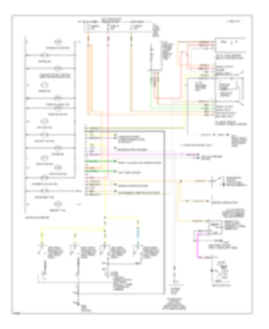
Instrument Cluster Wiring Diagram, Gauges Cluster, UB3 (2 of 2) for Buick Park Avenue Ultra 1995
List of elements for Instrument Cluster Wiring Diagram, Gauges Cluster, UB3 (2 of 2) for Buick Park Avenue Ultra 1995:
- (c-car) (h-car)
- (left front of eng compt, above left horn)
- A11
- Accy
- Air bag ind.
- Anti-lock brakes system
- Anti-theft system
- Antilock ind.
- Battery input
- Brake fluid level switch (master cylinder reservoir)
- Brake ind.
- Brake warning input
- Bulb test
- C 1995 vftc
- C b
- Change oil ind. ctrl
- Change oil soon ind.
- Check oil level ind.
- Coolant low ind.
- Cruise control systems
- Cruise ind.
- Door ajar ind.
- Engine controls system
- Fasten belt ind.
- Fuse 1d 15a
- Fuse 5a 10a
- Fuse 9c 10a
- G e
- G100
- G1o1 (right front of eng compt, above right horn)
- G200 (left kickpad)
- Hot at all times
- Hot in run
- Hot in run, bulb test or start
- I/p fuse block (left side of i/p)
- Ignition on input
- Ignition on/off timer
- Ignition switch
- Indicator control
- Information center
- J f
- Junction connector c340 (left front door sill, taped to composite harness)
- Left front door switch (top rear of left front door)
- Left rear door switch (top rear of left rear door)
- Lock
- Low
- Low coolant sensor (lower right rear of radia- tor)
- Low oil level sensor (below starter motor)
- Malfunction ind. lamp (mil) (service engine soon ind.)
- Multi-function chime (mfc) module (right of steering column support)
- Nca
- Normal
- Off
- Oil level module (in front of relay center)
- Park brake switch (top of park brake assembly)
- Pnk
- Power
- Powertrain control module (pcm) (behind right side of i/p, near kickpad)
- Right front door switch (top rear of right front door)
- Right rear door switch (top rear of right rear door)
- Run
- Security ind.
- Signal input
- Signal output
- Start
- Traction off ind.
- Trunk ajar ind.
- Trunk, tailgate, fuel doors system
- W/ traction control only
- W/ y67 reminder package only
- Warning systems
- Washer fluid low ind.
- Wiper/washer system (c-car only)