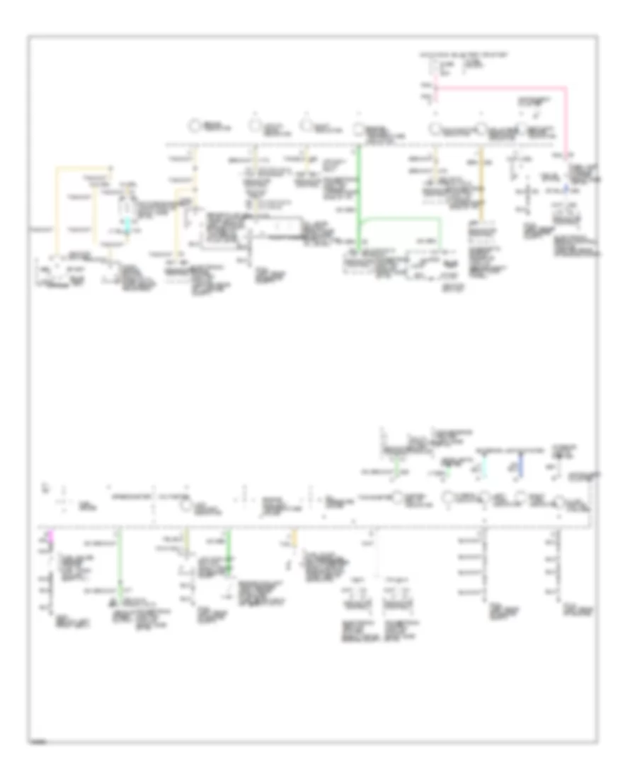
INSTRUMENT CLUSTER
Instrument Cluster Wiring Diagram, Base for Chevrolet Beretta 1994

List of elements for Instrument Cluster Wiring Diagram, Base for Chevrolet Beretta 1994:
-
- (not used)
- (vin a & 4) (vin m)
- (vin m) (vin 4 & a)
- (vin m) (vin a & 4)
- Abs lamp module (upper right side of i/p)
- Acc
- Antilock brake indicator
- Brake fluid level switch (left rear of engine compt) (closed w/ low brake fluid level)
- Brake indicator
- Bulb test
- C1 (vin a & 4) c1 (vin m)
- C2 c2
- C2 c3
- C3 (vin a & 4) c1 (vin m)
- C3 c2
- Charge indicator
- Convenience center (left side of i/p)
- Daytime running lamps module (right side of i/p)
- Diagnostic energy reserve module (behind right front kick panel)
- Electronic brake control module (center rear of engine compt)
- Electronic brake control module (center rear of luggage compt)
- Engine controls system
- Engine coolant temp sender (right rear of engine) (1365 @100 f,38 c) (55 @260 f,127 c)
- Engine coolant temperature gauge
- Engine coolant temperature indicator
- Exterior lights system
- Fasten belts indicator
- Float magnet
- Fuel gauge
- Fuel gauge sender (top of fuel tank) (full-90 ) (empty-0 )
- Fuel pump/ oil pressure switch/sender (right side of engine block) (open above 28kpa,4psi)
- Fuse 20a
- Fuse block
- G104 (left rear of engine compt)
- G114 (left rear of engine)
- G300 (below left front seat)
- Generator (right front of engine)
- Headlights system
- Hi beam indicator
- Hot in run, bulb test or start
- Ignition switch
- Illum- ination (2 bulbs)
- Indicator control
- Indicator control switch input
- Inflatable restraint indicator
- Instrument cluster
- Interior lights system
- Left turn indicator
- Lock
- Low coolant indicator
- Low coolant switch (right front of engine comp)
- Low oil level indicator
- Malfunction indicator
- Multi- function alarm module
- Nca
- Off
- Oil level switch (right side of engine) (open w/ low oil level)
- Oil pressure indicator
- Park brake switch (open with park brake released)
- Pnk
- Powertrain control module (right side of i/p)
- Powertrain control module (upper right side of i/p)
- Right turn indicator
- Run
- Shift indicator
- Solid state
- Speedometer
- Start
- Tan
- Vehicle speed output
- Vin a & 4 w/ m/t only
- Vin m only
- W/ drl
- W/o drl
Instrument Cluster Wiring Diagram, Gauges for Chevrolet Beretta 1994
List of elements for Instrument Cluster Wiring Diagram, Gauges for Chevrolet Beretta 1994:
-
- (vin a & 4) (vin m)
- (vin m) (vin 4 & a)
- (vin m) (vin a & 4)
- Abs lamp module (upper right side of i/p)
- Acc
- Antilock brake indicator
- Brake fluid level switch (left rear of engine compt) (closed w/ low brake fluid level)
- Brake indicator
- Bulb test
- C1 (vin a & 4) c1 (vin m)
- C2 c2
- C2 c3
- C3 (vin a & 4) c1 (vin m)
- C3 c2
- Convenience center (left side of i/p)
- Daytime running lamps module (right side of i/p)
- Diagnostic energy reserve module (behind right front kick panel)
- Electronic brake control module (center rear of engine compt)
- Electronic brake control module (center rear of luggage compt)
- Electronic ignition system (right top of engine compt)
- Engine coolant temp sender (right rear of engine) (1365 @100 f,38 c) (55 @260 f,127 c)
- Engine coolant temperature gauge
- Engine coolant temperature indicator
- Exterior lights system
- Fasten belts indicator
- Float magnet
- Fuel gauge
- Fuel gauge sender (top of fuel tank) (full-90 ) (empty-0 )
- Fuel pump/ oil pressure switch/sender (right side of engine block) (open above 28kpa,4psi)
- Fuse 20a
- Fuse block
- G104 (left rear of engine compt)
- G114 (left rear of engine)
- G300 (below left front seat)
- Headlights system
- Hi beam indicator
- Hot in run, bulb test or start
- Ignition switch
- Illum- ination (4 bulbs)
- Indicator control
- Indicator control switch input
- Inflatable restraint indicator
- Instrument cluster
- Interior lights system
- Left turn indicator
- Lock
- Low coolant indicator
- Low coolant switch (right front of engine comp)
- Low oil level indicator
- Malfunction indicator
- Multi- function alarm module
- Nca
- Off
- Oil level switch (right side of engine) (open w/ low oil level)
- Oil pressure gauge
- Park brake switch (open with park brake released)
- Pnk
- Powertrain control module (right side of i/p)
- Powertrain control module (upper right side of i/p)
- Right turn indicator
- Run
- Shift indicator
- Solid state
- Speedometer
- Start
- Tachometer
- Tan
- Vehicle speed output
- Vin 4 & a
- Vin a & 4 w/ m/t only
- Vin m
- Vin m only
- Voltmeter
- W/ drl
- W/o drl