INSTRUMENT CLUSTER
Driver Information Center Wiring Diagram for Chevrolet Corvette 1996

List of elements for Driver Information Center Wiring Diagram for Chevrolet Corvette 1996:
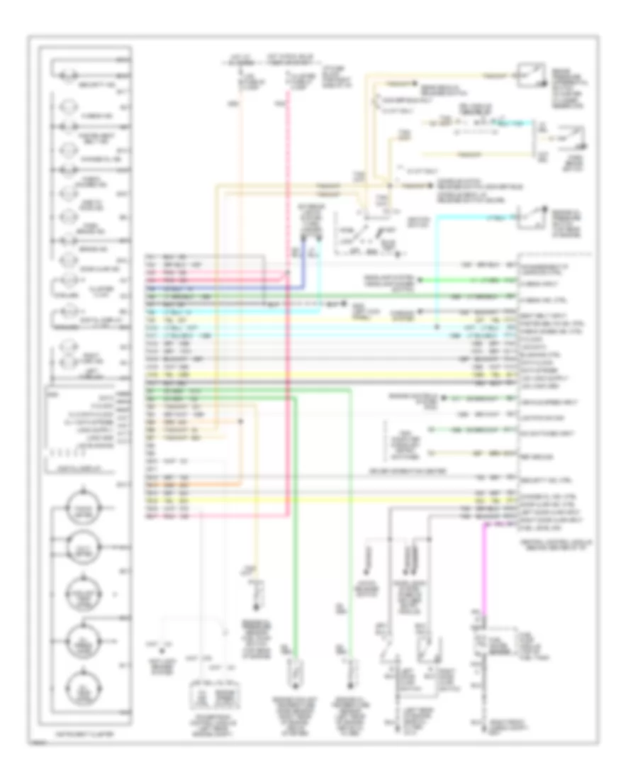
Instrument Cluster Wiring Diagram for Chevrolet Corvette 1996
List of elements for Instrument Cluster Wiring Diagram for Chevrolet Corvette 1996: