INSTRUMENT CLUSTER
Instrument Cluster Wiring Diagram (1 of 2) for Chevrolet Cutaway G3500 1999

List of elements for Instrument Cluster Wiring Diagram (1 of 2) for Chevrolet Cutaway G3500 1999:
- (4.3l/6.5l/7.4l: left side of eng, on cylinder head, 5.0l/5.7l: left cylinder head, between two front spark plugs)
- (7 bulbs)
- (engine harn, 14 cm from knock sensor) (4.3l) (engine harn, 8 cm from injector harn breakout) (5.0/5.7l) (engine harn, 10 cm from input shaft sensor) (7.4l) (engine harn, 4 cm from brake pressure differential switch) (6.5l diesel)
- (not used)
- A10
- A11
- A12
- A13
- A14
- A15
- A16
- A17
- Acc
- Air bag ind
- Anti-lock brakes system
- Anti-lock brakes warning ind
- B10
- B11
- B12
- B13
- B14
- B15
- B16
- B17
- Bat ind
- Brake ind in
- Brake pressure differential switch (part of electronic brake control module, left frame rail)
- Brake psi
- Brake tt
- Brake warning ind
- Check gauges ind
- Check gauges lamp driver
- Daytime running lamp control module (under left side of dash, taped to harness)
- Diesel only
- Diode-i d101
- Drl lamp ind
- Electronic brake control module (left frame rail, near center of vehicle)
- Eng-i mini fuse 20a
- Engine controls system
- Engine coolant temperature gauge sensor
- Exterior lights system
- Fuel gauge
- G101 (right front of engine compt)
- G110 (5.0, 5.7, 7.4l) (left front of engine)
- G110 (6.5l) (left front of engine)
- G119 (4.3l) (right front of engine)
- G119 (4.3l) (right frt of engine)
- G200 (behind left kick panel)
- Gauges fuse 4 10a
- Gnd
- Headlights system
- High beam ind
- Hot in run or start
- I/p fuse block (lower left kick panel)
- Ign
- Ign feed
- Ignition switch
- Illumin- ation lamps
- Ind ctrl
- Instrument cluster
- Interior lights system
- Left turn ind
- Lock
- Low coolant ind (diesel)
- Low engine coolant level indicator module (diesel only) (under left side of dash)
- Low engine coolant level indicator sensor (diesel only) (under coolant recovery/surge tank)
- Nca
- Off
- Oil press gauge
- Park/neutral position switch (left side of transmission)
- Pk brake
- Pnk
- Prndl circuit board
- Right turn ind
- Run
- S101
- S112
- S118
- S130
- S156
- S201
- S202
- S216
- Safety belt ind
- Service engine soon ind
- Service throttle soon ind (diesel)
- Solid state
- Speedometer/ odometer
- Start
- Starting/charging system
- Tan
- Temp gauge
- Underhood fuse-relay center (left side of eng compt)
- Underhood fuse-relay center (on left side of eng compt)
- Volt- meter
- Wait ind (diesel)
- Warning system engine controls system
- Water in fuel ind (diesel)
- Water-in-fuel sensor (diesel only) (left frame rail, near center of vehicle)
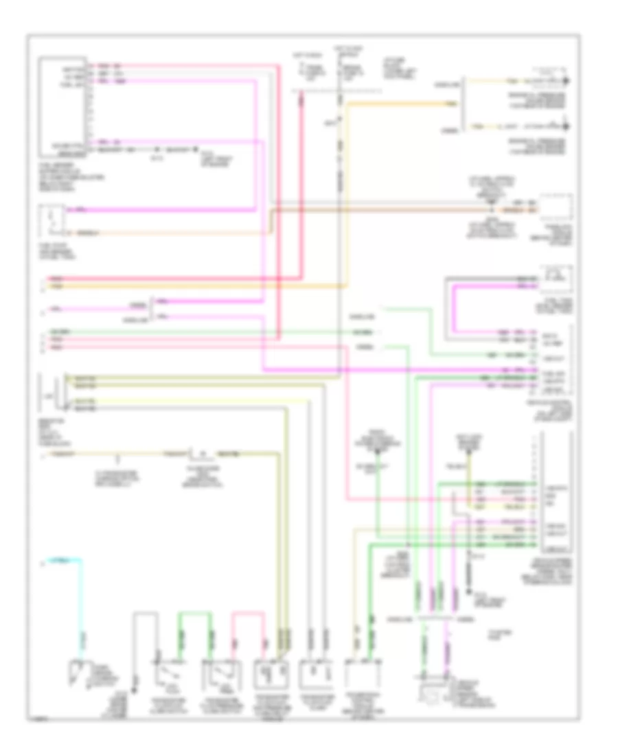
Instrument Cluster Wiring Diagram (2 of 2) for Chevrolet Cutaway G3500 1999
List of elements for Instrument Cluster Wiring Diagram (2 of 2) for Chevrolet Cutaway G3500 1999:
- (i/p harn, approx 21 cm from hvac switch breakout) s247
- (on inner knee bolster,
- +5v ref
- 1.5k
- Anti-lock brakes system
- Batt
- Below right side of dash)
- Brake fuse 18 10a
- Diesel
- Engine oil pressure gauge sender (top rear of engine)
- Engine oil pressure gauge sensor (top rear of engine)
- Fuel lev
- Fuel pump and sender (in fuel tank)
- Fuel sender buffer module
- Fuel sig
- Fuel tank level sender (in fuel tank)
- G110 (left front of engine)
- G116 (under brake master cylinder)
- Gasoline
- Gauge ctrl
- Gnd
- Hot in acc or run
- Hot in run
- I/p fuse block (lower left kick panel)
- Ign
- Ignition
- Inline diode d202 (near park brake switch)
- Low flow
- Low pres.
- P/b booster fluid flow alarm
- P/b booster fluid flow alarm switch
- P/b booster fluid flow and pressure alarm delay module
- P/b booster fluid pressure alarm switch
- Park brake warning switch
- Passlock module (behind center of dash)
- Pnk
- Powertrain control module (behind center of dash)
- Radio, electronic power steering system
- Resistor r208 (w/ uj1) (near i/p fuse block)
- S112
- S210
- S238 (i/p harn, 4 cm from cluster breakout)
- S246 (i/p harn, approx 25 cm from hvac switch breakout)
- Sens gnd
- Sense sw
- Sig in
- Tan
- Trans fuse 24 10a
- Twisted pair
- Vehicle control module (on left side of eng compt)
- Vehicle speed sensor (left side of transmission)
- Vehicle speed sensor buffer (diesel only) (below dash, near steering column)
- Vss out
- Vss rtn
- Vss sig
- W/ p/b booster warning option, rpo code-uj1