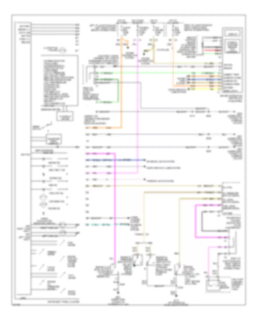
INSTRUMENT CLUSTER
Instrument Cluster Wiring Diagram for Chevrolet Impala SS 2005
List of elements for Instrument Cluster Wiring Diagram for Chevrolet Impala SS 2005:
- (if equipped)
- (main body wiring harness, left side of passenger compartment, 10 cm from c311 breakout)
- (or 685)
- (or 686)
- (or tan)
- (right front of engine, below power steering pump)
- -charge indicator
- -trunk open -change engine oil -traction active -over speed -low oil pressure -hot coolant temp -service traction system -reduced engine power -low tire pressure -intrusion on -intrusion off -door ajar -high beam out -low engine oil level -service vehicle soon -low brake fluid -security -low washer fluid -low fuel
- 3.4l
- 3.8l
- A/c- cruise fuse 10a
- Abs ind
- Air bag ind
- Ambient air temperature sensor (front of radiator support)
- Ambient temp
- Battery
- Boost gauge
- Brake fluid level switch (in master cylinder reservoir)
- Brake ind
- Brake lvl
- C10
- C12
- Check (malfunction indicator lamp-mil)
- Clstr/ bcm fuse 10a
- Computer data lines system
- Cruise ind
- Data line
- Dic/ rke fuse 10a
- Display
- Driver information center (dic)
- Engine coolant temper- ature gauge
- Engine oil level switch (open w/ low oil level) (3.8l) (left center of oil pan)
- Engine oil pressure (eop) switch
- Engine oil pressure (eop) switch (on left side of engine, above starter)
- Engine oil pressure gauge
- Exterior lights system
- Fuel gauge
- Fuel level sensor
- Fuel level sensor signal
- Fuel pump & sender assembly (in fuel tank)
- G113 (on transaxle stud, near starter)
- G201 (under dash, to right of steering column)
- G203 (under dash, to right of steering column)
- Gnd
- Ground
- High beam ind
- Hot at all times
- Hot in run
- Hot in run or start
- Ignition
- Illumination (7 bulbs)
- Instrument panel cluster
- Interior lights system
- Internal compass sensor (w/o sunroof)
- Left i/p junction block (left side of dash, behind access panel)
- Left turn ind
- Left turn input
- Logic
- Low ref
- Message center
- Mil ctrl
- Nca
- Odometer/ prndl display
- Oil level switch signal
- Oil pressure switch signal
- Pcm/bcm/ clstr fuse 10a
- Power distribution system
- Power tops system
- Powertrain control module (pcm) (in air cleaner box)
- Red
- Remote compass sensor (w/ sunroof) (in headliner console, left front of driver information center)
- Reset switch
- Right i/p junction block (right side of dash, behind access panel)
- Right turn ind
- Right turn input
- S106
- S174
- S229
- S236
- S253
- S322
- Seat belt ind
- Serial data
- Service engine soon ind
- Speedo- meter
- Sunroof close
- Sunroof open
- Sunroof sw
- Tacho- meter
- Trac off ind
- Vf display driver
- Volt- meter
- W/o police
- Wash lvl
- Wiper/ washer system
 English