INSTRUMENT CLUSTER
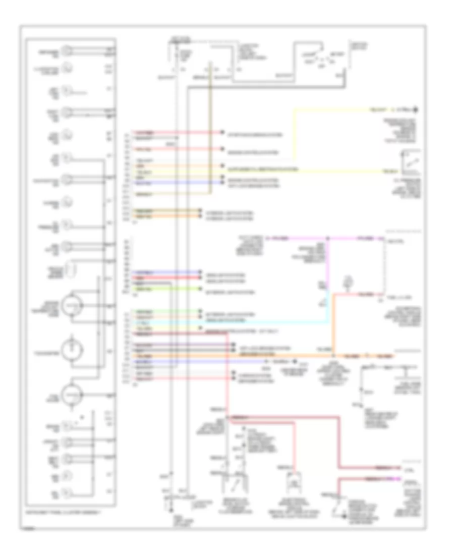
Instrument Cluster Wiring Diagram for Chevrolet Metro 1998
List of elements for Instrument Cluster Wiring Diagram for Chevrolet Metro 1998:
- (center rear of engine)
- (m/t only)
- 1.3l vin 9 only
- A10
- A11
- A12
- A13
- A14
- A15
- A16
- A16 c1
- Abs active ind
- Abs ind
- Accy
- Air bag ind
- Anti-lock brakes system
- B10
- B10 c2
- Brake fluid level switch (in brake fluid reservoir)
- Brake ind
- C1 b5
- C10
- C11
- C12
- C13
- C13 c3
- Charge ind
- Ctrl
- Data link connector (behind right side of dash)
- Daytime running lamps control module (behind left side of dash)
- Defogger ind
- Defogger system
- Drl ind
- Duty check
- Electronic brake control module (behind left side of dash, above junction block)
- Engine controls system
- Engine coolant temperature gage
- Engine coolant temperature sensor (on rear of engine, in t'stat housing)
- Exterior lights system
- Fuel gage sending unit (in fuel tank)
- Fuel gauge
- Fuel lvl sig
- G100 (lh front engine compt, on lh front inner fender, near battery)
- G131
- G202 (left side of dash)
- G407 (rear center of luggage compt, near deck lid striker)
- Headlights system
- High beam ind
- Hot in on and start
- Ig-coil fuse 15a
- Ignition switch
- Illumination (2 bulbs)
- Ind ctrl
- Instrument panel cluster assembly
- Interior lights system
- Junction block
- Junction block (on left side of dash)
- Left turn ind
- Lock
- Malfunction ind
- Off
- Oil pressure ind
- Oil pressure switch (left side of engine, above oil filter)
- Parking brake switch (under floor console, on parking brake lever base)
- Powertrain control module (behind right side of dash, near glove box)
- Red
- Right turn ind
- S213
- S223 (main harn, left rear of engine compt)
- S226 (dash harn, approx 2cm from cluster connector c3 breakout)
- S240
- S242
- S245
- S261 (engine harn, 4cm from pcm connectors breakout)
- S315
- Seat belt ind
- Signal
- Start
- Starting/charging system
- Tachometer
- Upshift ind (m/t)
- Vehicle speed sensor
- Warning system
 English