INSTRUMENT CLUSTER
Instrument Cluster Wiring Diagram for Dodge Dakota 1997

List of elements for Instrument Cluster Wiring Diagram for Dodge Dakota 1997:
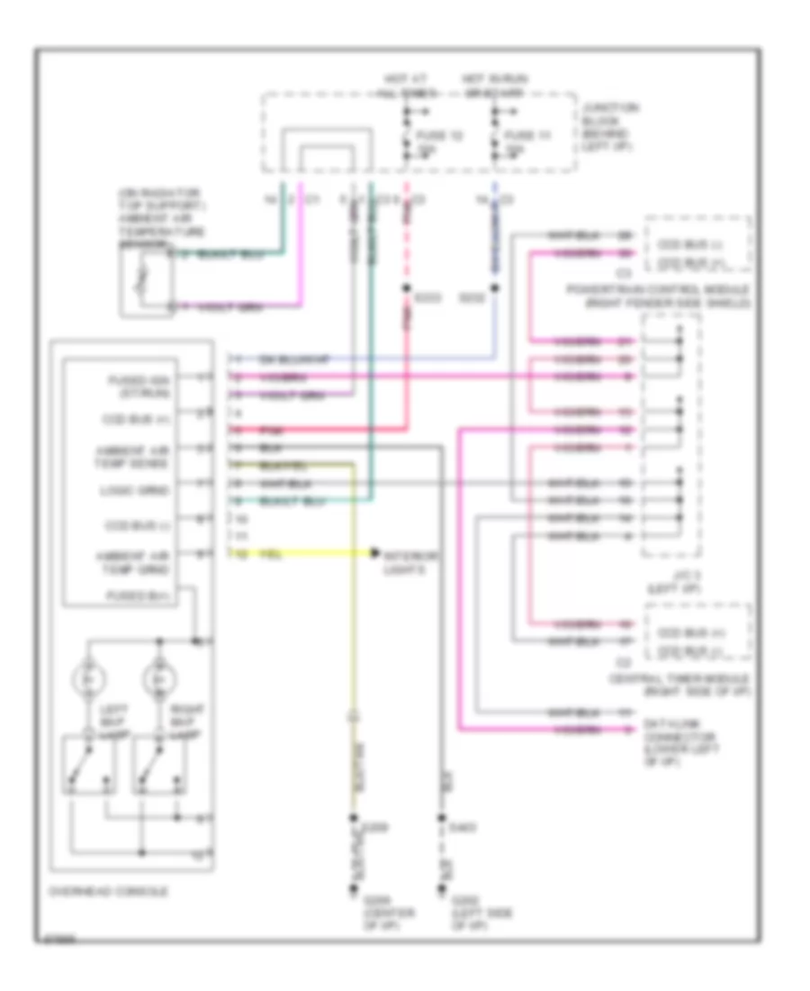
Overhead Console Wiring Diagram for Dodge Dakota 1997
List of elements for Overhead Console Wiring Diagram for Dodge Dakota 1997: