INSTRUMENT CLUSTER
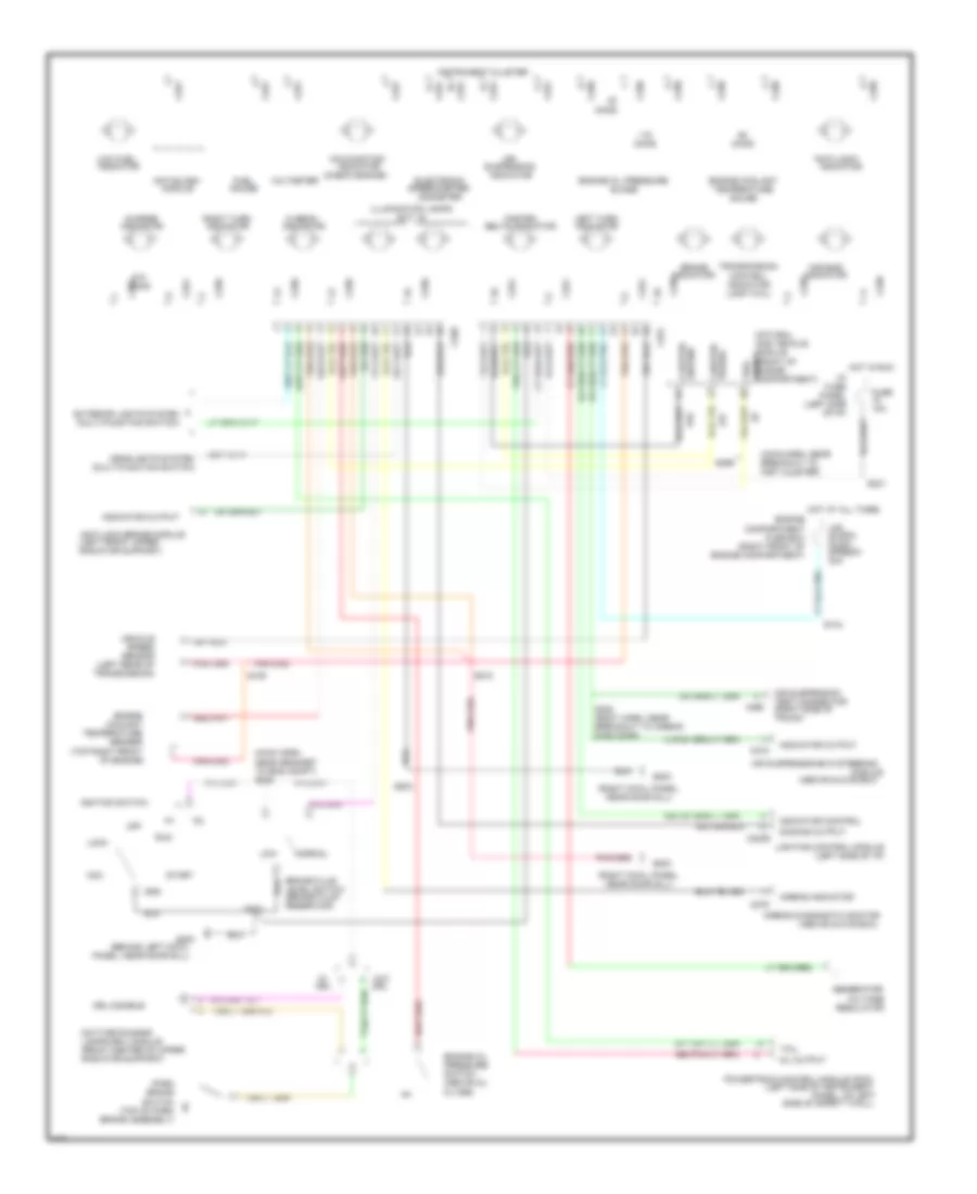
Analog Cluster Wiring Diagram for Ford Crown Victoria 1997

List of elements for Analog Cluster Wiring Diagram for Ford Crown Victoria 1997:
- "air bag"
- "anti-lock"
- (above glove box)
- (above oil
- (behind left cowl
- (brake fluid
- (check engine)
- (front center of upper
- (left front upper
- (left rear of
- (left side
- (left side of i/p)
- (left side of instrument
- (main harn,
- (main harn, near
- (multi-function switch)
- (qty. 6)
- (rear of
- (right cowl panel,
- (right front of
- (right side of
- (top of park
- (top right front
- 10a
- 15a
- 30a
- Acc
- Air
- Air suspension
- Air suspension/evo steering
- Airbag diagnostic monitor
- Airbag indicator
- Anti-lock brake module
- Anti-slosh
- Assembly
- At all
- Belts indicator
- Brake
- Brake assembly)
- Brake fluid
- Breakout to airbag
- C2029
- C215
- C250
- C251
- C276
- C459
- Charge
- Compartment
- Control
- Coolant
- Daytime running
- Diag conn)
- Dimming output
- Drl
- Drl disable
- Electronic
- Engine
- Engine compartment)
- Engine coolant
- Engine oil
- Engine oil pressure
- Exterior lights system
- Fasten
- Filter)
- Fuel
- Fuel tank)
- Fuse
- Fuse box
- G200
- G203
- Gauge
- Generator/
- Gnd
- Guage
- Headlights system
- Hi beam
- Hot
- Hot in
- I/p
- Ignition switch
- Illumination lamps
- In run
- Indicator
- Indicator control
- Indicator output
- Instrument cluster
- Lamp (tcil)
- Lamps (drl) module
- Left turn
- Level switch
- Lighting control module
- Lock
- Low
- Low fuel
- Malfunction
- Mil output
- Module
- Near door sill)
- Near grommet
- Normal
- Odometer
- Of engine)
- Of i/p)
- Off
- Ohms
- Or run
- Panel
- Panel, near door sill)
- Panel, on left
- Park
- Powertrain control module (pcm)
- Pressure
- Pump/
- Radiator support)
- Regulator
- Reservoir)
- Right turn
- Run
- S105
- S144
- S203
- S204
- S210
- S231
- S248
- S276
- S300
- Sender
- Sensor
- Side of safety wall)
- Speed
- Speedo
- Speedometer/
- Start
- Suspension
- Suspn
- Switch
- Tank
- Tcil
- Temperature
- Test connector
- Times
- To eng compt)
- Transmission
- Transmission)
- Trunk)
- Vehicle
- Voltage
- Voltmeter
- W/o
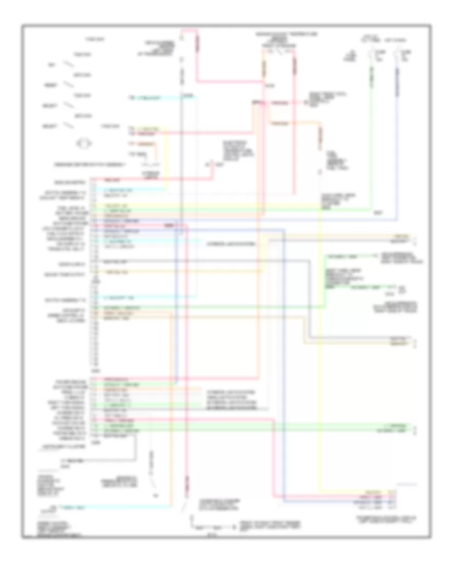
Analog Cluster Wiring Diagram, with Natural Gas for Ford Crown Victoria 1997
List of elements for Analog Cluster Wiring Diagram, with Natural Gas for Ford Crown Victoria 1997:
- "air bag"
- "anti-lock"
- (above glove box)
- (above oil
- (behind left cowl
- (body harn, near
- (brake fluid
- (check engine)
- (front center of upper
- (front of
- (left front upper
- (left rear of
- (left side
- (left side of i/p)
- (left side of instrument
- (main harn,
- (main harn, near
- (multi-function switch)
- (qty. 6)
- (right cowl panel,
- (right front of
- (right side of
- (top of park
- (top right front
- 10a
- 30a
- Acc
- Air
- Air suspension
- Air suspension/evo steering
- Airbag diagnostic monitor
- Airbag indicator
- Anti-lock brake module
- Anti-slosh
- Belts indicator
- Brake
- Brake assembly)
- Brake fluid
- Breakout to
- Breakout to airbag
- C2029
- C215
- C250
- C251
- C276
- C459
- Charge
- Cluster
- Compartment
- Compartment)
- Control
- Coolant
- Daytime running
- Diag conn)
- Dimming output
- Drl
- Drl disable
- Electronic
- Engine
- Engine compartment)
- Engine coolant
- Engine oil
- Engine oil pressure
- Exterior lights system
- Fasten
- Filter)
- Fuel
- Fuse
- Fuse box
- G200
- G203
- Gas vehicle
- Gauge
- Generator/
- Gnd
- Ground
- Guage
- Headlights system
- Hi beam
- Hot at all times
- Hot in run
- I/p
- Ignition switch
- Illumination lamps
- Indicator
- Indicator control
- Indicator output
- Inst cluster)
- Instrument cluster
- Lamp (tcil)
- Lamps (drl) module
- Left turn
- Level switch
- Lighting control module
- Lock
- Low
- Low fuel
- Malfunction
- Mil output
- Module
- Natural
- Near door sill)
- Near grommet
- Normal
- Odometer
- Of engine)
- Of i/p)
- Off
- Ohms
- Panel
- Panel, near door sill)
- Panel, on left
- Park
- Power
- Powertrain control module (pcm)
- Pressure
- Pump/
- Radiator support)
- Regulator
- Reservoir)
- Right turn
- Run
- S105
- S144
- S203
- S204
- S210
- S231
- S248
- S299
- S300
- Sender
- Sensor
- Side of safety wall)
- Signal
- Speed
- Speedo
- Speedometer/
- Start
- Suspension
- Suspn
- Switch
- Tcil
- Temperature
- Test connector
- To eng compt)
- Transmission
- Transmission)
- Trunk)
- Vehicle
- Voltage
- Voltmeter
- W/o
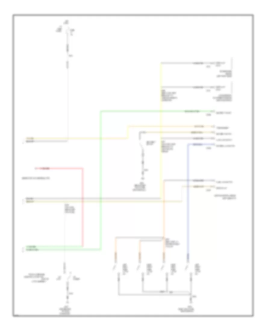
Electronic Cluster Wiring Diagram (1 of 2) for Ford Crown Victoria 1997
List of elements for Electronic Cluster Wiring Diagram (1 of 2) for Ford Crown Victoria 1997:
- (above oil filter)
- (behind right
- (body harn, near
- (front of right front fender
- (in fluid reservoir)
- (left rear
- (left rear of
- (left side of safety wall)
- (main harn, near
- (rear of
- (right front cowl
- (right side of trunk)
- (top right
- 15a
- 17400 ohm
- 2670 ohm
- 7320 ohm
- Air bag
- Air susp in
- Air suspension
- Air suspension/
- Airbag diagnostic
- Airbag ind in
- All times
- Apron, right side of battery)
- Assembly
- Automatic
- Battery power
- Breakout to
- C215
- C227
- C254
- C255
- C256
- C276
- Charge ind in
- Cluster)
- Connector)
- Control (eatc)
- Coolant temp sens in
- Deck lid open
- Diagnostic
- Dim display in
- Door ajar in
- Door sill)
- E/m
- Electronic
- Engine compartment)
- Engine coolant temperature
- Engine oil
- English/metric
- Evo steering module
- Exterior lights system
- Fasten belts in
- Front of engine)
- Fuel
- Fuel flow rate in
- Fuel level in
- Fuel tank)
- Fuse
- G101
- G203
- Headlights system
- Hi beam in
- Hot at
- Hot in run
- I/p
- Ind
- Instrument cluster
- Interior
- Interior lights system
- Left turn signal
- Lights
- Low fluid switch
- Low washer fluid in
- Malfunction ind
- Message center switch assembly
- Module
- Monitor
- Of transmission)
- Oil pres ind in
- Out
- Output
- Panel
- Panel, near
- Power ground
- Powertrain control module
- Pressure switch
- Prndl illum
- Red 506
- Reset
- Right turn signal
- S105
- S109
- S112
- S202
- S210
- S227
- S269
- S300
- Select
- Sens ground
- Sensor
- Servo assembly
- Side of i/p)
- Sound tone output
- Speed control
- Speed control in
- Switch assembly in
- Switched power
- Tank
- Temperature
- Test connector
- Trans ctrl ind lt
- Vehicle speed
- Vehicle speed in +
- Windshield washer
Electronic Cluster Wiring Diagram (2 of 2) for Ford Crown Victoria 1997
List of elements for Electronic Cluster Wiring Diagram (2 of 2) for Ford Crown Victoria 1997:
- (above glove box)
- (behind right
- (body harn, at
- (body harn, near
- (center rear
- (left front door)
- (left side of i/p)
- (main harn,
- (main harn, near
- (part of
- (right cowl panel,
- 10a
- A pillar)
- Air suspension
- Airbag diagnostic
- Ajar
- Ajar lamp output
- Behind left
- Breakout to
- C2026
- C2027
- C2029
- C216
- C518
- Center of right
- Closed
- Connector)
- Cowl panel,
- Decklid jar
- Door
- Door ajar
- Driver's ajar switch
- Driver's door
- Evo steering module
- Front
- Fuse
- G203
- G407
- Generator/voltage regulator
- Hot
- I/p
- In run
- Input
- Kick panel)
- Latch
- Latch assembly)
- Left
- Lid
- Lighting control module
- Lighting ctrl
- Module
- Module)
- Near door sill)
- Of trunk
- On support)
- Panel
- Pass. ajar switch
- Rear
- Right
- S231
- S257
- S268
- S273
- S277
- S304
- S403
- S500
- S600
- Seat belt
- Seatbelt ind out
- Seatbelt switch
- Solenoid ajar switch
- Switch
- Tone request
- Trunk lid release
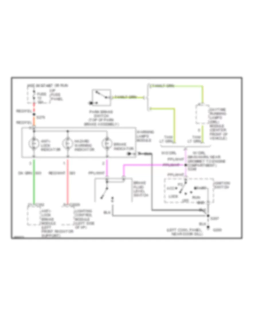
Warning Lights Wiring Diagram for Ford Crown Victoria 1997
List of elements for Warning Lights Wiring Diagram for Ford Crown Victoria 1997:
- (left cowl panel, near door sill)
- Acc
- Anti- lock brake module (left front radiator support)
- Anti- lock indicator
- Brake fluid level switch
- Brake indicator
- C162
- C2026
- Daytime running lamps (drl) module (center front of vehicle)
- Fuse 15a
- G200
- Gnd
- Hazard warning indicator
- Hot in start or run
- I/p fuse panel
- Ignition switch
- Lighting control module (left side of i/p)
- Lock
- Off
- Park brake switch (top of park brake assembly)
- Run
- S207
- S276
- Start
- W/ drl
- W/o drl
- Warning lamps module