INSTRUMENT CLUSTER
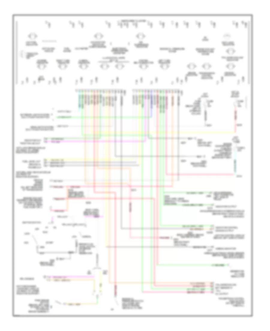
Analog Cluster Wiring Diagram for Ford Crown Victoria Police Interceptor 1998

List of elements for Analog Cluster Wiring Diagram for Ford Crown Victoria Police Interceptor 1998:
- "air bag"
- "anti-lock"
- "fail-safe cooling"
- "traction
- (behind left
- (behind left side
- (behind left side of dash)
- (behind right
- (behind right side of dash,
- (below dash,
- (body harn,
- (body harness, behind
- (check engine)
- (dash
- (engine harn,
- (in right front
- (left side of
- (main harn, near
- (multi-function switch)
- (on brake
- (on front of upper
- (on left rear side
- (on left side of
- (on lower left
- (on rear of
- (on top
- (qty. 6)
- 10a
- 15a
- 30a
- Above glove box)
- Above oil filter)
- Acc
- Air
- Air suspension
- Air suspension/evo steering module
- Airbag electronic crash sensor
- Airbag indicator
- Anti-lock brake module
- Anti-slosh
- Assembly
- Assist"
- At all
- Behind
- Behind battery)
- Behind right
- Belts indicator
- Brake
- Brake assembly)
- Brake fluid
- Breakout to airbag
- C2029
- C215
- C250
- C251
- C277
- C459
- Center of dash)
- Charge
- Column)
- Compartment
- Control
- Control module (pcm)
- Corner of
- Daytime running
- Diag conn)
- Dimming output
- Drl
- Drl disable
- Ect sensor in
- Electronic
- Engine
- Engine compt)
- Engine compt,
- Engine coolant
- Engine oil
- Engine oil pressure
- Exterior lights system
- Fail-safe cooling
- Fasten
- Firewall)
- Fluid
- Fuel
- Fuel injector 1)
- Fuel level in
- Fuel tank)
- Fuse
- Fuse 8
- Fuse box
- G200
- G203
- Gauge
- Generator/
- Gnd
- Guage
- Harn,
- Headlights system
- Hi beam
- Hot
- Hot in
- I/p
- Ignition switch
- Illumination lamps
- In run
- Indicator
- Indicator control
- Indicator out
- Indicator output
- Instrument cluster
- Kick panel)
- Lamps (drl) module
- Left of
- Left rear of
- Left side
- Left turn
- Level switch
- Lighting control module
- Lock
- Low
- Low fuel
- Malfunction
- Mil out
- Module
- Normal
- Odometer
- Of dash)
- Of dash, on top
- Of engine, near
- Of parking
- Of transmission)
- Off
- Ohms
- Or run
- Panel
- Park brake
- Powertrain
- Pressure switch
- Radiator support)
- Regulator
- Reservoir)
- Right front
- Right turn
- Run
- S105
- S144
- S202
- S203
- S204
- S207
- S209
- S210
- S222
- S231
- S276
- S287
- S300
- Sender
- Sensor
- Side of dash)
- Side of engine,
- Speed
- Speedometer/
- Start
- Steering
- Suspension
- Switch
- Tank
- Tcil
- Temperature
- Test connector
- Times
- Traction ind out
- Transmission
- Trunk)
- Vehicle
- Voltage
- Voltmeter
- W/o
Analog Cluster Wiring Diagram, with Natural Gas for Ford Crown Victoria Police Interceptor 1998
List of elements for Analog Cluster Wiring Diagram, with Natural Gas for Ford Crown Victoria Police Interceptor 1998:
- "air bag"
- "anti-lock"
- "fail-safe cooling"
- "traction
- (behind left
- (behind left side
- (behind left side of dash)
- (behind right
- (behind right side of dash,
- (below dash,
- (body harn,
- (body harness, behind
- (check engine)
- (engine harn,
- (in right front
- (left side of
- (main harn, near
- (multi-function switch)
- (on brake
- (on front of
- (on front of upper
- (on left rear side
- (on left side of
- (on lower left
- (on top right front
- (qty. 6)
- 10a
- 15a
- 30a
- Above glove box)
- Above oil filter)
- Acc
- Air
- Air suspension
- Air suspension/evo steering module
- Airbag electronic crash sensor
- Airbag indicator
- Anti-lock brake module
- Anti-slosh
- Assist"
- At all
- Behind battery)
- Behind right
- Belts indicator
- Brake
- Brake assembly)
- Brake fluid
- Breakout to airbag
- C2029
- C215
- C250
- C251
- C277
- C459
- Center of dash)
- Charge
- Column)
- Compartment
- Control
- Corner of
- Daytime running
- Diag conn)
- Dimming output
- Drl
- Drl disable
- Ect sensor in
- Electronic
- Engine
- Engine compt)
- Engine compt,
- Engine coolant
- Engine oil
- Engine oil pressure
- Exterior lights system
- Fail-safe cooling
- Fasten
- Firewall)
- Fluid
- Fuel
- Fuel injector 1)
- Fuel level out
- Fuse
- Fuse 8
- Fuse box
- G200
- G203
- Gauge
- Generator/
- Gnd
- Ground in
- Guage
- Headlights system
- Hi beam
- Hot
- Hot in
- I/p
- Ignition switch
- Illumination lamps
- In run
- Ind
- Indicator
- Indicator control
- Indicator out
- Indicator output
- Instrument cluster
- Kick panel)
- Lamps (drl) module
- Left of
- Left rear of
- Left turn
- Level switch
- Lighting control module
- Lock
- Low
- Low fuel
- Malfunction
- Mil output
- Module
- Module (pcm)
- Natural gas vehicle module
- Normal
- Odometer
- Of dash, on top
- Of engine, near
- Of parking
- Of transmission)
- Off
- Ohms
- Or run
- Panel
- Park brake
- Power out
- Powertrain control
- Pressure switch
- Radiator support)
- Regulator
- Reservoir)
- Right turn
- Run
- S105
- S144
- S203
- S204
- S207
- S209
- S210
- S222
- S231
- S276
- S287
- S300
- Sensor
- Side of dash)
- Side of engine,
- Speed
- Speedometer/
- Start
- Steering
- Suspension
- Switch
- Tcil
- Temperature
- Temperature sender
- Test connector
- Times
- Traction ind out
- Transmission
- Trunk)
- Vehicle
- Voltage
- Voltmeter
- W/o
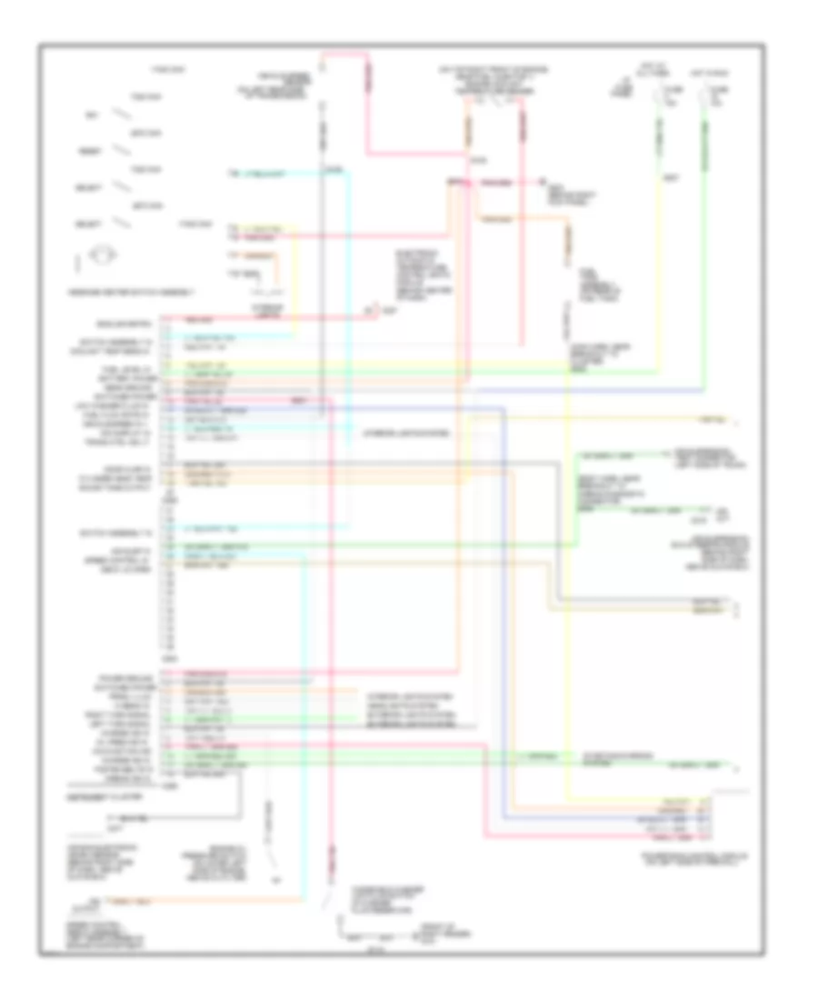
Electronic Cluster Wiring Diagram (1 of 2) for Ford Crown Victoria Police Interceptor 1998
List of elements for Electronic Cluster Wiring Diagram (1 of 2) for Ford Crown Victoria Police Interceptor 1998:
- (behind center
- (behind right
- (behind right side
- (body harn, near
- (front of
- (in washer
- (left rear corner of
- (left side of trunk)
- (main harn, near
- (on left rear side
- (on left side of firewall)
- (on lower left
- (on rear of
- (on top right front of engine,
- 10a
- 15a
- 17400 ohm
- 2670 ohm
- 7320 ohm
- Above glove box)
- Above oil filter)
- Air bag electronic
- Air susp in
- Air suspension
- Air suspension/
- Airbag diagnostic
- Airbag ind in
- All times
- Assembly
- Automatic
- Battery power
- Breakout to
- C215
- C227
- C254
- C255
- C256
- C277
- Charge ind in
- Cluster)
- Connector)
- Control (eatc)
- Coolant temp sens in
- Crash sensor
- Cylinder head temp
- Deck lid open
- Dim display in
- Door ajar in
- E/m
- Electronic
- Engine compartment)
- Engine coolant
- Engine oil
- English/metric
- Evo steering module
- Exterior lights system
- Fasten belts in
- Fluid reservoir)
- Fuel
- Fuel flow rate in
- Fuel level in
- Fuel tank)
- Fuse
- G101
- G203
- Glove box)
- Headlights system
- Hi beam in
- Hot at
- Hot in run
- I/p
- Ind
- Instrument cluster
- Interior
- Interior lights system
- Kick panel)
- Left turn signal
- Lights
- Low fluid switch
- Low washer fluid in
- Malfunction ind
- Message center switch assembly
- Module
- Near fuel injector 1)
- Of dash)
- Of dash, above
- Of transmission)
- Oil pres ind in
- Out
- Output
- Panel
- Power ground
- Powertrain control module
- Pressure switch
- Prndl illum
- Red 506
- Reset
- Right fender)
- Right turn signal
- S105
- S109
- S112
- S202
- S210
- S227
- S231
- S300
- Select
- Sens ground
- Sensor
- Servo assembly
- Side of dash,
- Side of engine,
- Sound tone output
- Speed control
- Speed control in
- Starting/charging
- Switch assembly in
- Switched power
- System
- Tank
- Temperature
- Temperature sender
- Test connector
- Trans ctrl ind lt
- Vehicle speed
- Vehicle speed in +
- Windshield washer
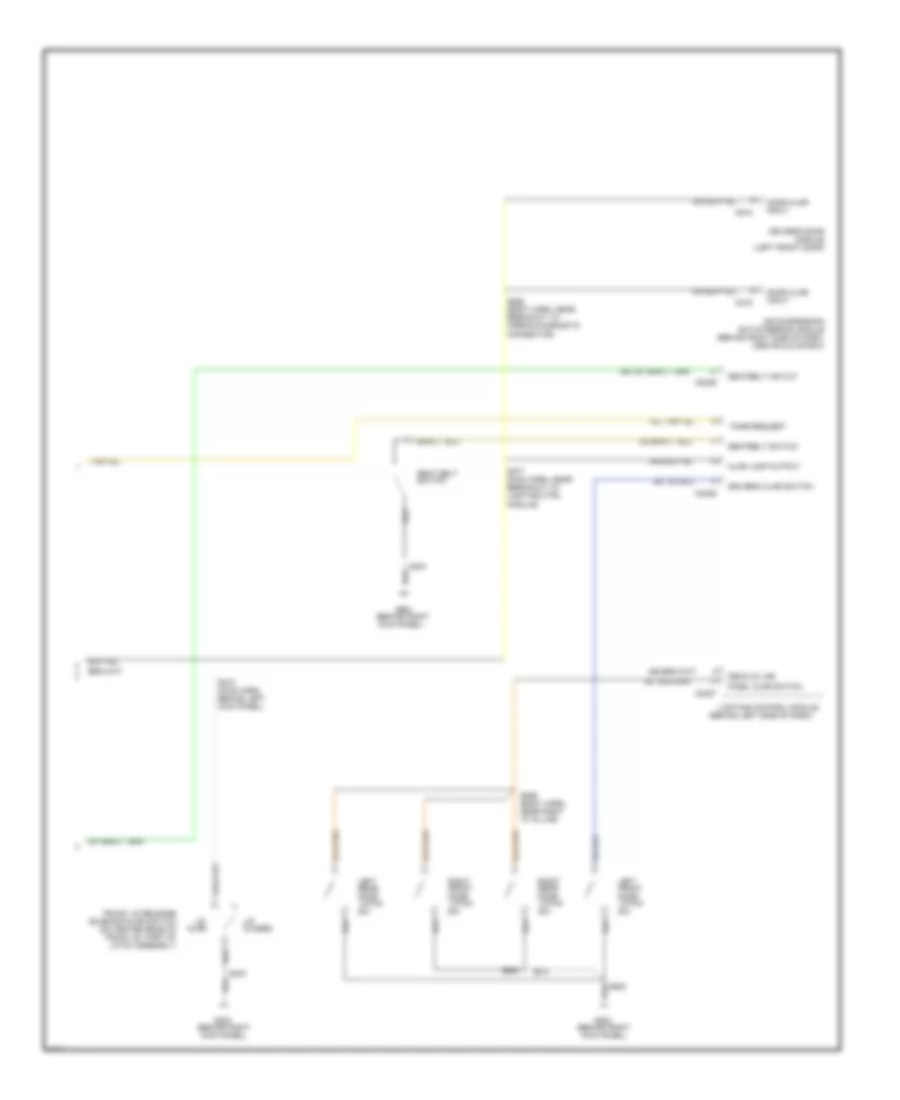
Electronic Cluster Wiring Diagram (2 of 2) for Ford Crown Victoria Police Interceptor 1998
List of elements for Electronic Cluster Wiring Diagram (2 of 2) for Ford Crown Victoria Police Interceptor 1998:
- "a" pillar)
- (above glove box)
- (behind left side of dash)
- (behind right
- (behind right side of dash,
- (body harn,
- (body harn, near
- (left front door)
- (main harn,
- (main harn, near
- (on center rear of
- Air suspension
- Airbag diagnostic
- Ajar
- Ajar lamp output
- Behind left
- Breakout to
- C2026
- C2027
- C2029
- C216
- C518
- Closed
- Connector)
- Decklid jar
- Door
- Door ajar
- Driver's ajar switch
- Driver's door
- Evo steering module
- Front
- G203
- Input
- Kick panel)
- Latch
- Latch assembly)
- Left
- Lid
- Lighting control module
- Lighting ctrl
- Module
- Module)
- Near right
- Pass. ajar switch
- Rear
- Right
- S259
- S268
- S273
- S277
- S304
- S403
- S500
- S600
- Seat belt
- Seatbelt ind out
- Seatbelt switch
- Solenoid/ajar switch
- Switch
- Tone request
- Trunk lid release
- Trunk lid, part of
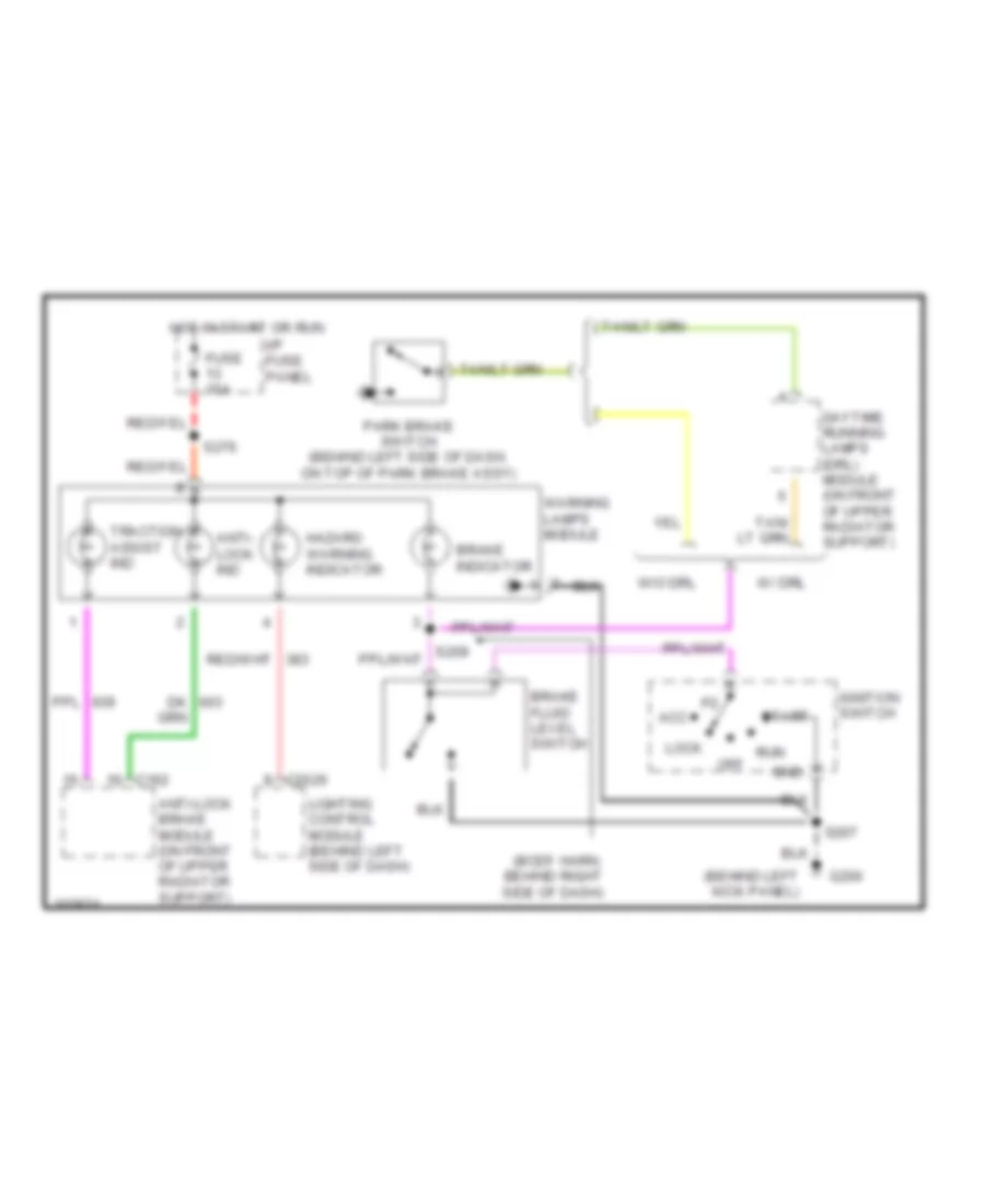
Electronic Cluster Warning Lamps Wiring Diagram for Ford Crown Victoria Police Interceptor 1998
List of elements for Electronic Cluster Warning Lamps Wiring Diagram for Ford Crown Victoria Police Interceptor 1998:
- (behind left kick panel)
- (body harn, behind right side of dash)
- Acc
- Anti- lock ind
- Anti-lock brake module (on front of upper radiator support)
- Brake fluid level switch
- Brake indicator
- C162
- C2026
- Daytime running lamps (drl) module (on front of upper radiator support)
- Fuse 15a
- G200
- Gnd
- Hazard warning indicator
- Hot in start or run
- I/p fuse panel
- Ignition switch
- Lighting control module (behind left side of dash)
- Lock
- Off
- Park brake switch (behind left side of dash, on top of park brake assy)
- Run
- S207
- S276
- Start
- Traction assist ind
- W/ drl
- W/o drl
- Warning lamps module