INSTRUMENT CLUSTER
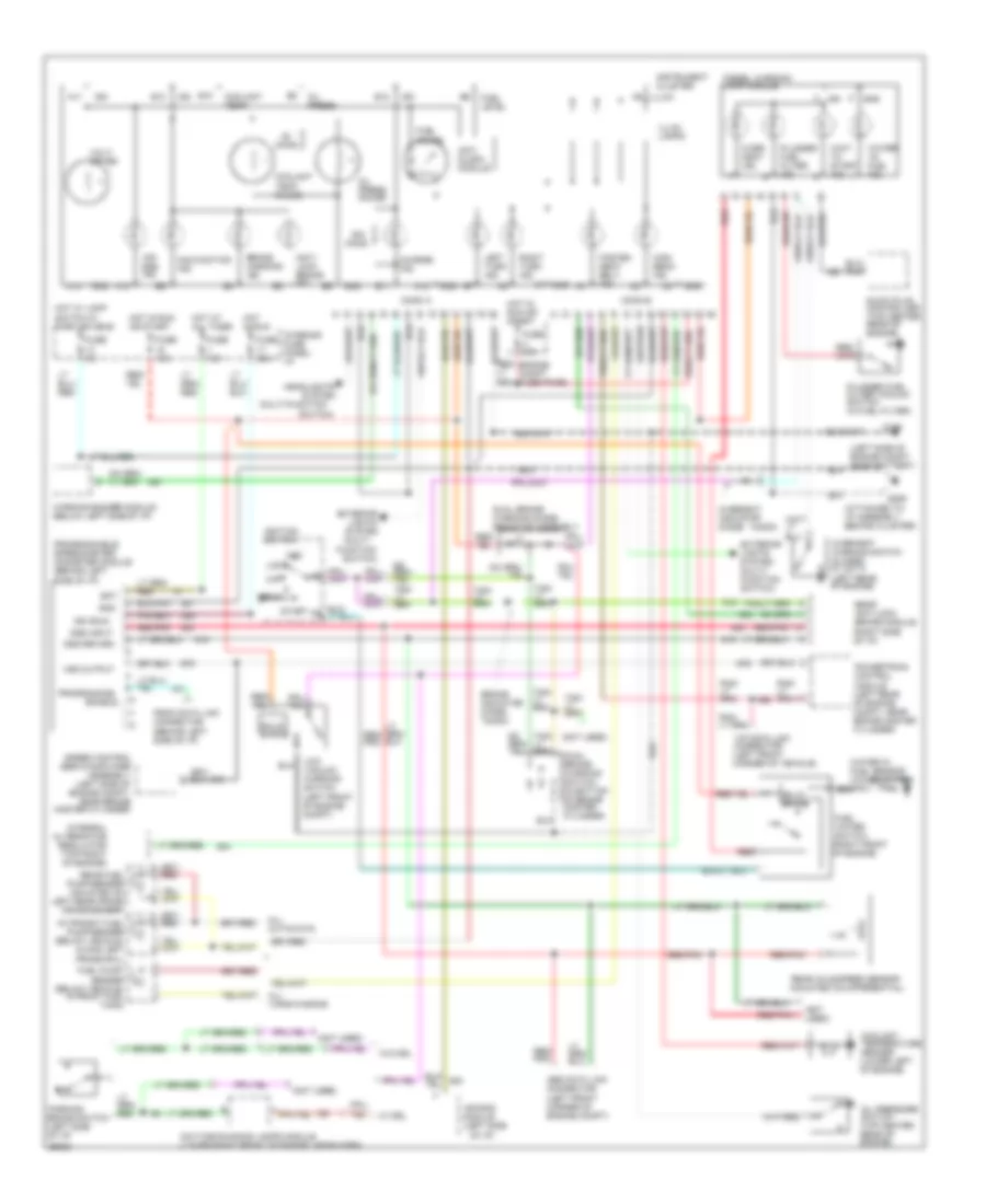
Diesel Engine Wiring Diagram, with 4 Wheel ABS for Ford Econoline E250 1994

List of elements for Diesel Engine Wiring Diagram, with 4 Wheel ABS for Ford Econoline E250 1994:
- (attached to i/p assembly, behind cluster)
- (left front frame rail)
- (left side
- (left side of engine compt, near battery)
- (not used)
- 1.4k
- 1n4003
- 4wabs
- A10
- A11
- A12
- A14
- Abs data link connector (left front corner of engine compt)
- Acc
- Air bag ind.
- Air bag module (left side of i/p)
- All cutaways
- All vans/wagons
- Alternator
- Amplifier assembly (left side of engine compt, near brake master cylinder)
- Anti slosh module
- Anti- lock brake ind.
- B10
- B11
- B12
- B13
- Bat
- Brake switch
- Brake warning ind.
- Charge ind.
- Conn a
- Conn b
- Control module
- Coolant temp.
- Coolant temp. gauge
- Coolant temperature sender (lower left of engine)
- Daytime running lamps module (lower right front of engine, near horn)
- Diesel warning lamp module
- Dss input
- Dss return
- Dual brake warning switch (in bottom of brake master cylinder)
- Enable
- Engine compt fuse panel
- Exterior lights system (multi- function switch)
- Fasten seat belt ind.
- Fuel gauge
- Fuel level
- Fuel pump/ sender (below vehicle, in front fuel tank)
- Fuel water switch (right front of engine)
- Fuse 15a
- Fuse 20a
- Fuse 5a
- Fuse u 30a
- G106
- G206
- Glow plug controller (top center rear of engine)
- Gnd
- Headlights system (multi- function switch)
- High beam ind.
- Hot at all times
- Hot in run
- Hot in run or start
- Hot w/ lamp switch in park or head
- Ign
- Ign (run)
- Ignition switch
- Illum.
- Illum. lamps
- In-transit fuel pump/sender (below vehicle, along left frame rail)
- Instrument cluster
- Integral
- Interior fuse panel: i/p
- Left turn ind.
- Lock
- Low vacuum warning switch (left front of engine compt)
- Malfunction ind.
- Of i/p)
- Off
- Ohms
- Oil press.
- Oil press. gauge
- Oil pressure switch (top center rear of engine)
- Over- heat ind.
- Overheat indicator diode-
- Overheat warning switch (closed at 247 f) (left rear of engine)
- Parking
- Plugged fuel filter ind.
- Plugged fuel filter vacuum switch (in fuel filter)
- Powertrain control module (left rear of engine compt, near brake master cylinder)
- Programmable speedometer/ odometer module (behind left side of i/p)
- Programming
- Psom data link connector (behind left side of i/p)
- Rear axle speed sensor (mounted on differential)
- Rear fuel pump/sender (mounted on left rear frame crossmember)
- Red
- Red/ pnk
- Red/pnk
- Regulator (top right of engine)
- Right turn ind.
- Run
- Solid state
- Speed control servo/
- Start
- Vip data link connector (left front corner of vehicle)
- Volt- meter
- Vss output
- W/ drl
- W/o drl
- Wait to start ind.
- Warning buzzer module (below left side of i/p)
- Water -in- fuel ind.
- Water in fuel sensor (in fuel filter)
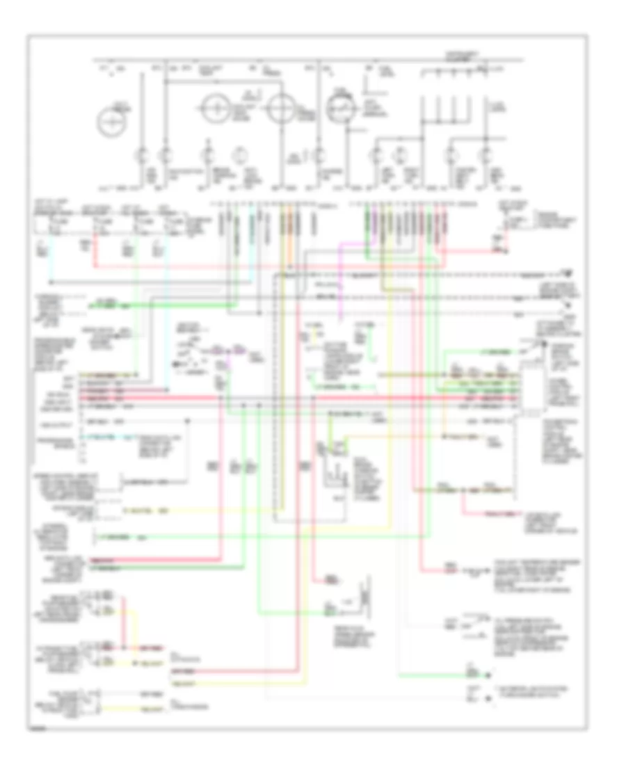
Diesel Engine Wiring Diagram, with Rear Wheel ABS for Ford Econoline E250 1994
List of elements for Diesel Engine Wiring Diagram, with Rear Wheel ABS for Ford Econoline E250 1994:
- (attached to i/p assembly, behind cluster)
- (left side
- (left side of engine compt, near battery)
- (multi-function
- (not used)
- (right side of i/p)
- 1.4k
- 1n4003
- A10
- A11
- A12
- A14
- Abs data link connector (left front corner of engine compt)
- Acc
- Air bag ind.
- Air bag module
- All cutaways
- All vans/wagons
- Anti slosh module
- Anti- lock brake ind.
- B10
- B11
- B12
- B13
- Bat
- Brake indicator diode- 1n4003
- Brake warning ind.
- Charge ind.
- Conn a
- Conn b
- Coolant temp.
- Coolant temp. gauge
- Coolant temperature sender (lower left of engine)
- Daytime running lamps module (lower right front of engine, near horn)
- Diesel warning lamp module
- Dss input
- Dss return
- Dual brake warning diode/ resistor assembly
- Dual brake warning switch (in bottom of brake master cylinder)
- Enable
- Engine compt fuse panel
- Exterior
- Exterior lights system (multi- function switch)
- Fasten seat belt ind.
- Fuel gauge
- Fuel level
- Fuel pump/ sender (below vehicle, in front fuel tank)
- Fuel water switch (right front of engine)
- Function
- Fuse 15a
- Fuse 20a
- Fuse 5a
- Fuse u 30a
- G106
- G206
- Glow plug controller (top center rear of engine)
- Gnd
- Headlights
- High beam ind.
- Hot at all times
- Hot in run
- Hot in run or start
- Hot w/ lamp switch in park or head
- Ign
- Ign (run)
- Ignition switch
- Illum.
- Illum. lamps
- In-transit fuel pump/sender (below vehicle, along left frame rail)
- Instrument cluster
- Integral alternator regulator (top right of engine)
- Interior fuse panel: i/p
- Left turn ind.
- Lights system (multi-
- Lock
- Low vacuum warning switch (left front of engine compt)
- Malfunction ind.
- Of i/p)
- Off
- Ohms
- Oil press.
- Oil press. gauge
- Oil pressure switch (top center rear of engine)
- Over- heat ind.
- Overheat indicator diode-
- Overheat warning switch (closed at 247 f) (left rear of engine)
- Parking brake switch (left side of i/p)
- Plugged fuel filter ind.
- Plugged fuel filter vacuum switch (in fuel filter)
- Powertrain control module (left rear of engine compt, near brake master cylinder)
- Programmable speedometer/ odometer module (behind left side of i/p)
- Programming
- Psom data link connector (behind left side of i/p)
- Rear anti-lock brake module
- Rear axle speed sensor (mounted on differential)
- Rear fuel pump/sender (mounted on left rear frame crossmember)
- Red
- Red/ pnk
- Red/pnk
- Right turn ind.
- Run
- Solid state
- Speed control servo/amplifier assembly (left side of engine compt, near brake master cylinder)
- Start
- Switch)
- System
- Vip data link connector (left front corner of vehicle)
- Volt- meter
- Vss output
- W/ drl
- W/o drl
- Wait to start ind.
- Warning buzzer module (below left side of i/p)
- Water -in- fuel ind.
- Water in fuel sensor (in fuel filter)
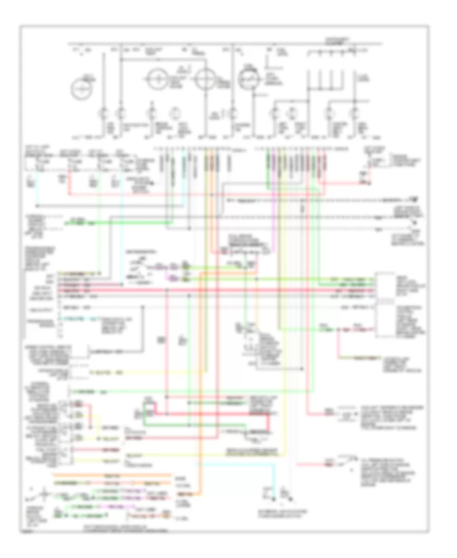
Gas Engine Wiring Diagram, with 4 Wheel ABS for Ford Econoline E250 1994
List of elements for Gas Engine Wiring Diagram, with 4 Wheel ABS for Ford Econoline E250 1994:
- (attached to i/p assembly, behind cluster)
- (below left side of i/p)
- (dimmer
- (left front
- (left front frame rail)
- (left side of engine compt, near battery)
- (not used)
- 1.4k
- 4wabs control module
- A10
- A11
- A12
- A14
- Abs data link
- Acc
- Air bag ind.
- Air bag module (left side of i/p)
- All cutaways
- All vans/wagons
- Anti slosh module
- Anti- lock brake ind.
- B10
- B11
- B12
- B13
- Bat
- Brake warning ind.
- Charge ind.
- Conn a
- Conn b
- Connector
- Coolant temp.
- Coolant temp. gauge
- Coolant temperature sender (4.9l-right rear of engine, near fuel injector #6) (5.0l & 5.8l-lower left of engine) (7.5l-lower right of engine)
- Corner of
- Daytime running lamps module (lower right front of engine, near horn)
- Dss input
- Dss return
- Dual brake warning switch (in bottom of brake master cylinder)
- Enable
- Engine compartment fuse panel
- Engine compt)
- Exterior lights system (turn/hazard switch)
- Fasten seat belt ind.
- Fuel gauge
- Fuel level
- Fuel pump/ sender (below vehicle, in front fuel tank)
- Fuse 15a
- Fuse 20a
- Fuse 5a
- Fuse u 30a
- G106
- G206
- Gnd
- Headlights
- High beam ind.
- Hot at all times
- Hot in run
- Hot in run or start
- Hot w/ lamp switch in park or head
- Ign
- Ign (run)
- Ignition switch
- Illum.
- Illum. lamps
- In-transit fuel pump/sender (below vehicle, along left frame rail)
- Instrument cluster
- Integral alternator regulator (top right of engine)
- Interior fuse panel: i/p
- Left turn ind.
- Lock
- Malfunction ind.
- Off
- Ohms
- Oil press.
- Oil press. gauge
- Oil pressure switch (4.9l-left side of engine, near distributor) (5.0l & 5.8l-front of engine, near a/c compressor) (7.5l-top center rear of engine)
- Parking brake switch (left side of i/p)
- Powertrain control module (left rear of engine compt, near brake master cylinder)
- Programmable speedometer/ odometer module (behind left side of i/p)
- Programming
- Psom data link connector (behind left side of i/p)
- Rear axle speed sensor (mounted on differential)
- Rear fuel pump/sender (mounted on left rear frame crossmember)
- Red/ pnk
- Red/pnk
- Right turn ind.
- Run
- Speed control servo/ amplifier assembly (left side of engine compt, near brake master cylinder)
- Start
- Switch)
- System
- Vip data link connector (left front corner of vehicle)
- Volt- meter
- Vss output
- W/ drl
- W/o drl
- Warning buzzer module
Gas Engine Wiring Diagram, with Rear Wheel ABS for Ford Econoline E250 1994
List of elements for Gas Engine Wiring Diagram, with Rear Wheel ABS for Ford Econoline E250 1994:
- (attached to i/p assembly, behind cluster)
- (below left side of i/p)
- (dimmer
- (left side of engine compt, near battery)
- (not used)
- (right side of i/p)
- 1.4k
- A10
- A11
- A12
- A14
- Abs data link connector (left front corner of engine compt)
- Acc
- Air bag ind.
- Air bag module (left side of i/p)
- All cutaways
- All vans/wagons
- Amplifier assembly (left side of engine compt, near brake master cylinder)
- Anti slosh module
- Anti- lock brake ind.
- B10
- B11
- B12
- B13
- Base
- Bat
- Brake warning ind.
- Charge ind.
- Conn a
- Conn b
- Coolant temp.
- Coolant temp. gauge
- Coolant temperature sender (4.9l-right rear of engine, near fuel injector #6) (5.0l & 5.8l-lower left of engine) (7.5l-lower right of engine)
- Daytime running lamps module (lower right front of engine, near horn)
- Dss input
- Dss return
- Dual brake warning diode/ resistor assembly
- Dual brake warning switch (in bottom of brake master cylinder)
- Enable
- Engine compartment fuse panel
- Exterior lights system (turn/hazard switch)
- Fasten seat belt ind.
- Fuel gauge
- Fuel level
- Fuel pump/ sender (below vehicle, in front fuel tank)
- Fuse 15a
- Fuse 20a
- Fuse 5a
- Fuse u 30a
- G106
- G206
- Gnd
- Headlights
- High beam ind.
- Hot at all times
- Hot in run
- Hot in run or start
- Hot w/ lamp switch in park or head
- Ign
- Ign (run)
- Ignition switch
- Illum.
- Illum. lamps
- In-transit fuel pump/sender (below vehicle, along left frame rail)
- Instrument cluster
- Integral alternator regulator (top right of engine)
- Interior fuse panel: i/p
- Left turn ind.
- Lock
- Malfunction ind.
- Off
- Ohms
- Oil press.
- Oil press. gauge
- Oil pressure switch (4.9l-left side of engine, near distributor) (5.0l & 5.8l-front of engine, near a/c compressor) (7.5l-top center rear of engine)
- Parking brake switch (left side of i/p)
- Powertrain control module (left rear of engine compt, near brake master cylinder)
- Programmable speedometer/ odometer module (behind left side of i/p)
- Programming
- Psom data link connector (behind left side of i/p)
- Rear anti-lock brake module
- Rear axle speed sensor (mounted on differential)
- Rear fuel pump/sender (mounted on left rear frame crossmember)
- Red
- Red/ pnk
- Red/pnk
- Right turn ind.
- Run
- Speed control servo/
- Start
- Switch)
- System
- Vip data link connector (left front corner of vehicle)
- Volt- meter
- Vss output
- W/ drl
- W/ drl jumper
- W/o drl
- Warning buzzer module