INSTRUMENT CLUSTER
Instrument Cluster Wiring Diagram (1 of 2) for GMC Vandura G3500 1996

List of elements for Instrument Cluster Wiring Diagram (1 of 2) for GMC Vandura G3500 1996:
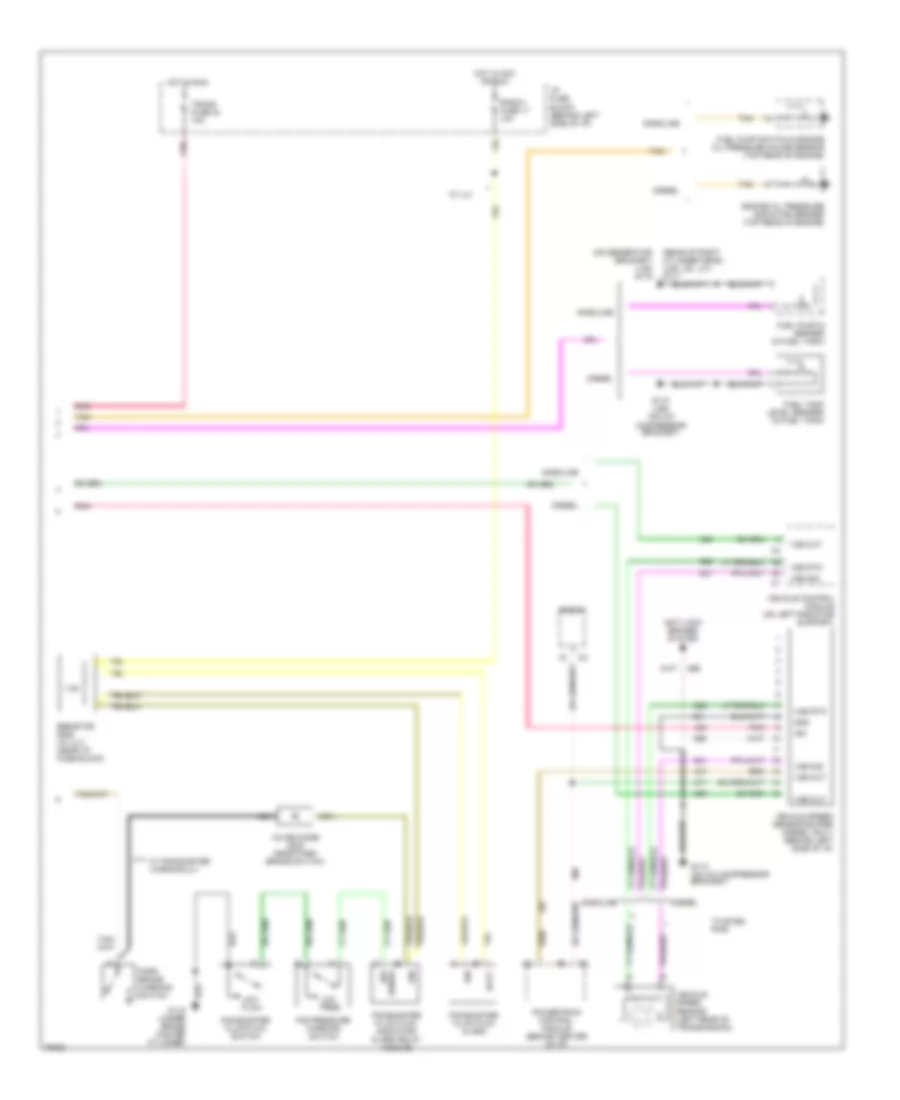
Instrument Cluster Wiring Diagram (2 of 2) for GMC Vandura G3500 1996
List of elements for Instrument Cluster Wiring Diagram (2 of 2) for GMC Vandura G3500 1996: