INSTRUMENT CLUSTER
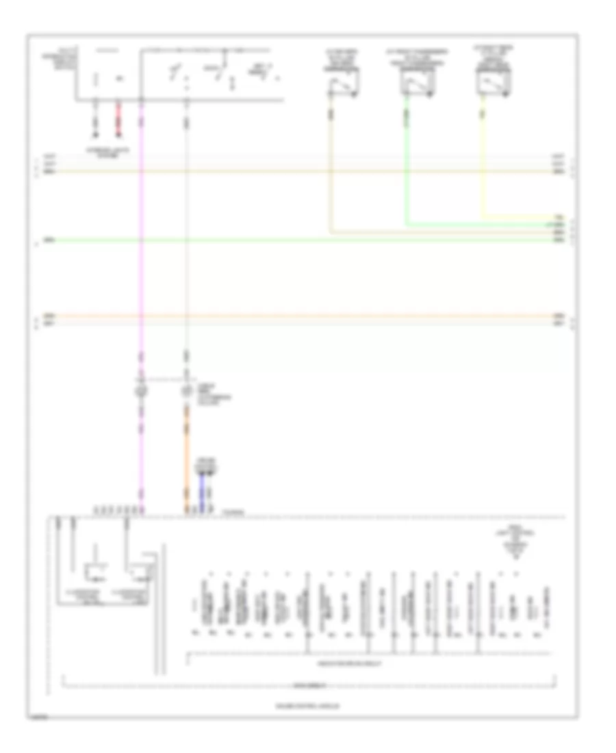
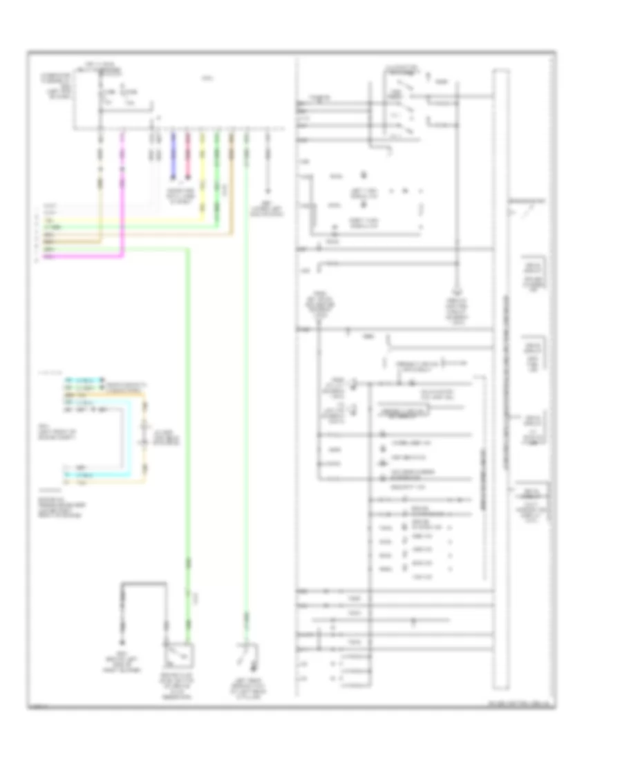
Instrument Cluster Wiring Diagram, Except Hybrid (1 of 3) for Honda Accord Plug-In 2014

List of elements for Instrument Cluster Wiring Diagram, Except Hybrid (1 of 3) for Honda Accord Plug-In 2014:
- (3.5l: right side of engine compt) (2.4l: left side of engine compt) pcm
- 2.4l
- 3.5l
- 5v control circuit
- 5v on/off
- A10
- A11
- A12
- A13
- A14
- A15
- A16
- A17
- A18
- A19
- A20
- A21
- A22
- A23
- A24
- A25
- A26
- A27
- A28
- A29
- A30
- A31
- A32
- Amp
- Anti-lock brakes system
- Audio unit/ audio navigation unit (if equipped)
- B-can h
- B-can l
- B-can transceiver
- B19
- B34
- B43
- B45
- B47
- C109
- C122
- Computer data lines system
- Cruise control ind
- Cruise control main switch ind
- Cruise control system
- Dc-dc converter
- Dimming circuit
- Driver (cog)
- Driver's junction box
- Eco ind
- Econ switch
- Eeprom
- Except sport
- Except touring
- Exterior lights system
- F-can h
- F-can l
- F-can transceiver
- Front fog light ind
- Fuse 10a
- G502 (upper left end of dash)
- Gauge control module
- Head-up warning unit
- Hot at all times
- Illumination control & dimming circuit for ambient (green)
- Illumination control & dimming circuit for ambient (white)
- Illumination control & dimming circuit for car outline (white)
- Illumination control & dimming circuit for dial face (white)
- Illumination control & dimming circuit for lcd back light (amber)
- Illumination control & dimming circuit for lcd back light (white)
- Illumination control & dimming circuit for pointer (white)
- Illumination control & dimming circuit for sub scale (white)
- Indicator drive circuit
- Interior lights system
- J/c c012 (touring) c019 (except touring) (touring: left rear of engine compt)
- J/c c015 (touring) j/c c017 (except touring) (touring: left rear of engine) (except touring: (left rear engine compt)
- Keyless access control unit (left side of dash)
- Lcd (dot)
- Lights-on ind
- Lin transceiver
- Main circuit
- Multi- information display
- Oil pressure switch (2.4l) (lower right front of engine)
- Parking brake switch
- Pnk
- Power seat control unit (under driver's seat)
- Red
- Rocker arm oil pressure sensor (3.5l) (top front of right cylinder bank)
- Shift to parking ind
- Speaker
- Sport
- Stabilize circuit
- Sub pcb
- To immobilizer ind (diagram 3 of 3)
- To malfunction ind lamp (mil) (diagram 3 of 3)
- To pin a28 (diagram 3 of 3)
- Touring
- Under-hood fuse/relay box (left side of engine compt)
- Warning systems
- Wiper/washer system
- X'tal
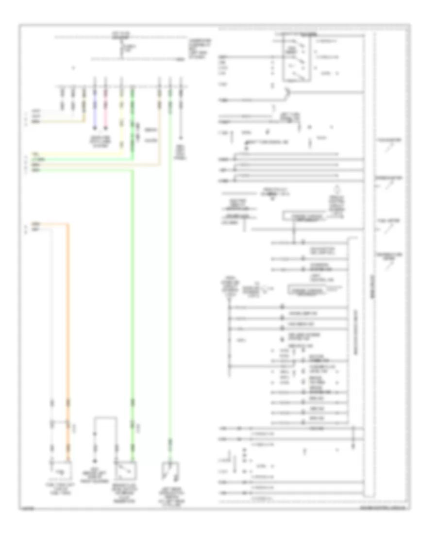
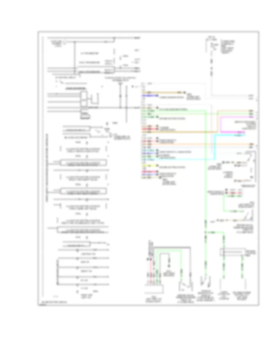
Instrument Cluster Wiring Diagram, Except Hybrid (2 of 3) for Honda Accord Plug-In 2014
List of elements for Instrument Cluster Wiring Diagram, Except Hybrid (2 of 3) for Honda Accord Plug-In 2014:
- (at driver's "b" pillar) driver's door switch
- (at front passenger's "b" pillar) front passenger's door switch
- (at right rear "c" pillar) (sedan) right rear door switch
- A13
- A14
- A15
- A16
- A32
- Acc ind (amber)
- B10
- B11
- Cable reel (in steering column)
- Collision ind forward
- Cruise control system
- Cutoff ind side air bag
- Door ind
- Down
- From light control ind (diagram 3 of 3)
- Fuel empty ind
- Gauge control module
- Illumination control (bulb)
- Illumination control (led)
- Ind (red)
- Indicator drive circuit
- Information ind multi-
- Interior lights system
- Left front door ind
- Left rear door ind
- Low oil pressure
- Main circuit
- Multi- information display switch
- Pressure ind low tire
- Red
- Reminder ind seat belt
- Requirement ind maintenance
- Right front door ind
- Right rear door ind
- Set/ reset
- Starter system ind
- Touring
- Trunk ind
- Vsa off ind
- Warning ind lane departure
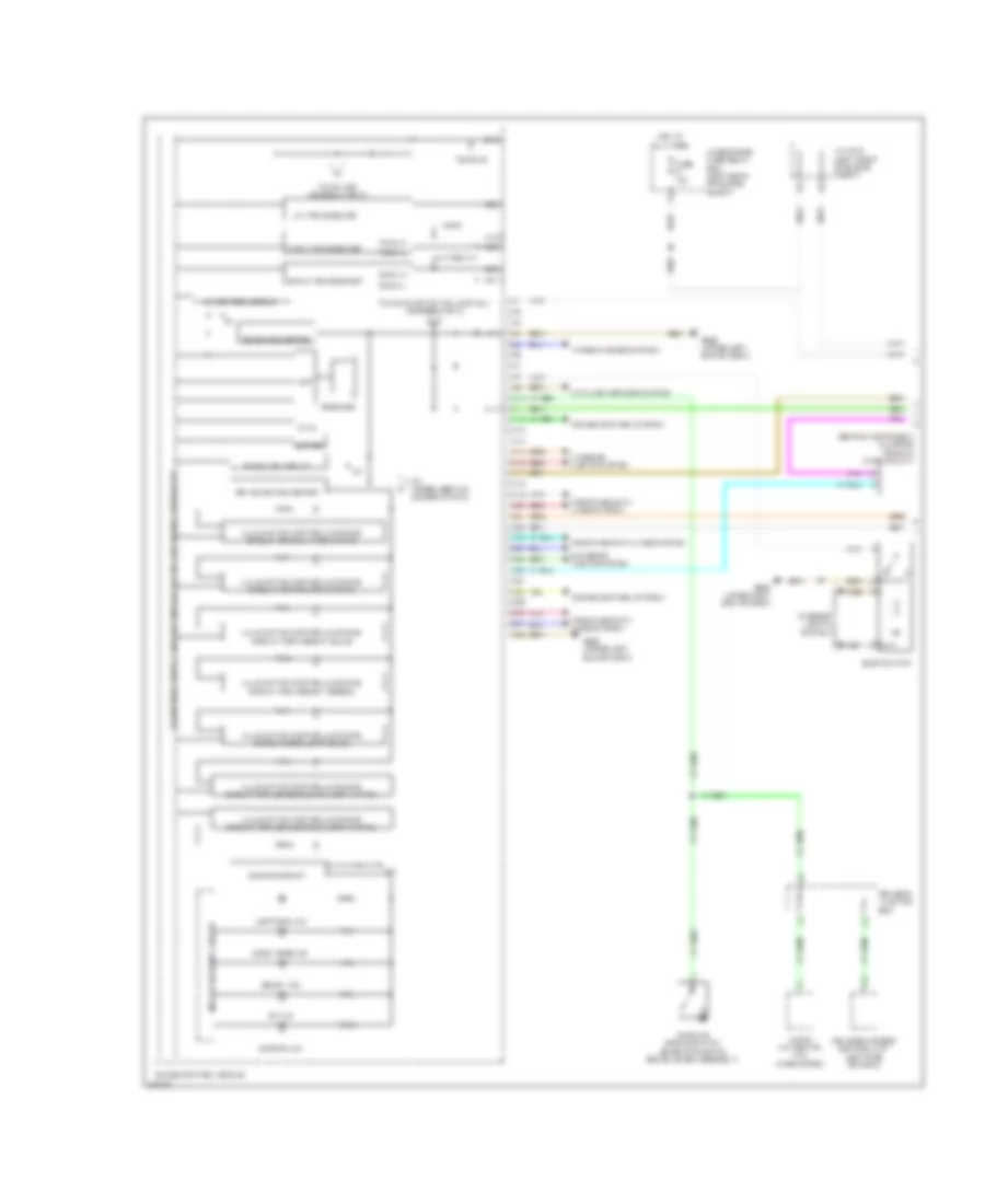
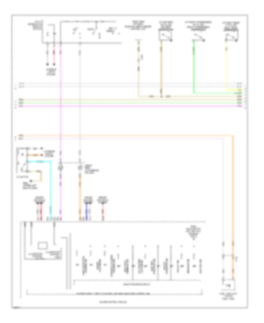
Instrument Cluster Wiring Diagram, Except Hybrid (3 of 3) for Honda Accord Plug-In 2014
List of elements for Instrument Cluster Wiring Diagram, Except Hybrid (3 of 3) for Honda Accord Plug-In 2014:
- A10
- A11
- A12
- A21
- A24
- A25
- A26
- A28
- Abs ind
- B10
- B11
- Brake fluid level switch (on brake fluid reservoir)
- Brake ind (red)
- Brake system ind
- C105
- C111
- C112
- Charging system ind
- Computer data lines system
- Coupe
- D22
- D23
- D30
- Driver (cog)
- E23
- Eps ind
- Forced turning- off circuit
- Forced turning- on circuit
- From 5v control circuit (diagram 1 of 3)
- From pin a17 (diagram 1 of 3)
- From stabilize circuit (diagram 1 of 3)
- Fuel meter
- Fuel tank unit (top of fuel tank)
- Fuse 5 7.5a
- G301 (behind left side of front bumper)
- G601 (left kick panel)
- Gauge control module
- High beam ind
- Hot in on or start
- Ill +
- Ill -
- Illumination encoder
- Immobilizer ind
- Indicator drive circuit
- Keyless access system ind
- Lcd (seg)
- Left rear door switch (sedan) (at left rear "c" pillar)
- Left turn signal ind
- Light control ind
- M11
- M12
- Main circuit
- Malfunction ind lamp (mil)
- Micu
- Odo/trip (seg) at s-matic lcd
- Pnk
- R10
- Right turn signal ind
- Rotate wheel ind
- S13
- S14
- Security ind
- Sedan
- Speedometer
- Srs ind
- Tachometer
- Temperature meter
- To door ind (diagram 2 of 3)
- Trip reset
- Under-dash fuse/relay box (left end of dash)
- Vsa ind
- Washer fluid level ind
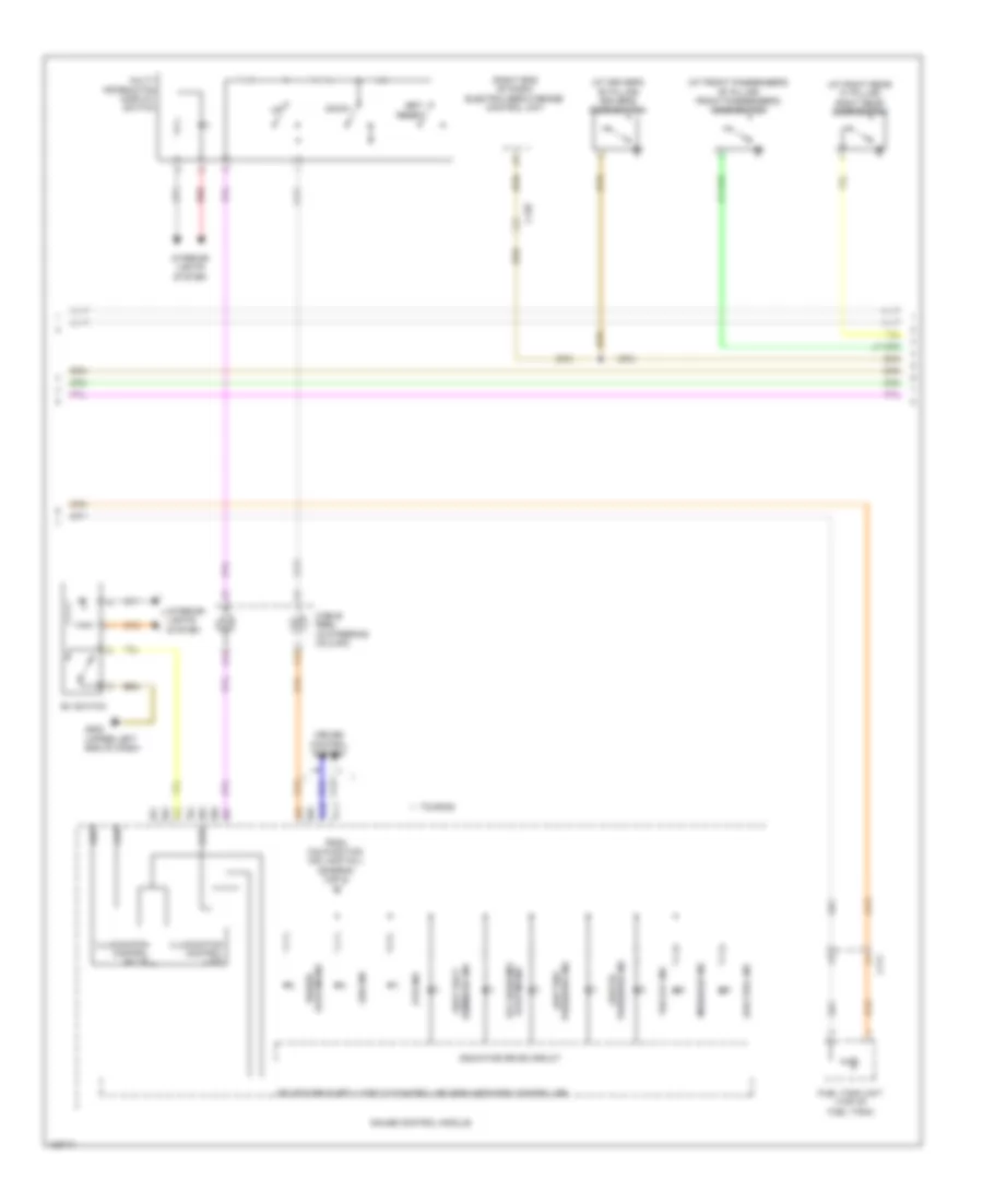
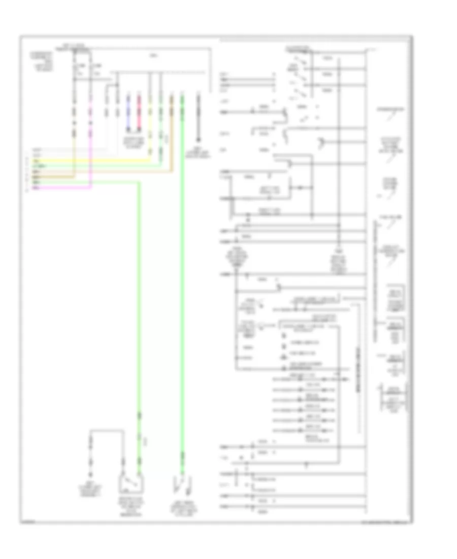
Instrument Cluster Wiring Diagram, Hybrid (1 of 3) for Honda Accord Plug-In 2014
List of elements for Instrument Cluster Wiring Diagram, Hybrid (1 of 3) for Honda Accord Plug-In 2014:
- (behind instrument cluster) head-up warning unit
- 10v
- 26v dc-dc converter
- 5v control circuit
- A10
- A11
- A12
- A13
- A14
- A15
- A16
- A17
- A18
- A19
- A20
- A21
- A22
- A23
- A24
- A25
- A26
- A27
- A28
- A29
- A30
- A31
- A32
- Amp
- Anti-lock brakes system
- Audio/ navigation unit (if equipped)
- B-can h
- B-can l
- B-can transceiver
- B10
- B19
- Computer data lines system
- Cruise control system
- Dc-dc converter
- Dimming circuit
- Driver's junction box
- E-drive ind
- Econ mode ind
- Econ switch
- Eeprom
- Ev ind
- Exterior lights system
- F-can h
- F-can l
- F-can transceiver
- Fuse 10a
- G502 (upper left end of dash)
- Gauge control module
- Hot at all times
- Illumination control & dimming circuit for ambient (green)
- Illumination control & dimming circuit for dial face (white)
- Illumination control & dimming circuit for lcd (mid) back light (white)
- Illumination control & dimming circuit for lcd (seg) back light (white)
- Illumination control & dimming circuit for pointer (white)
- Indicator drive circuit
- Interior lights system
- J/c c012 (left front of engine compt)
- Keyless access control unit (left side of dash)
- Lights-on ind
- Lin transceiver
- Parking brake switch (base of parking brake lever assembly)
- Pnk
- Ready ind
- Red
- Speaker
- Stabilize circuit
- To immobilizer ind (diagram 3 of 3)
- To malfunction ind lamp (mil) (diagram 3 of 3)
- To pin a28 (diagram 3 of 3)
- Touring
- Under-hood fuse/relay box (left rear of engine compt)
- Wiper/washer system
- X'tal
Instrument Cluster Wiring Diagram, Hybrid (2 of 3) for Honda Accord Plug-In 2014
List of elements for Instrument Cluster Wiring Diagram, Hybrid (2 of 3) for Honda Accord Plug-In 2014:
- (at driver's "b" pillar) driver's door switch
- (at front passenger's "b" pillar) front passenger's door switch
- (at right rear "c" pillar) right rear door switch
- (right end of dash) electric servo brake control unit
- 12v charging system ind
- A13
- A14
- A15
- A16
- A32
- B10
- B11
- C111
- C128
- Cable reel (in steering column)
- Cruise control system
- Down
- Ev switch
- Fcw ind
- From malfunction ind lamp (mil) (diagram 3 of 3)
- Fuel tank unit (top of fuel tank)
- G502 (upper left end of dash)
- Gauge control module
- Illumination control (bulb)
- Illumination control (led)
- Indicator drive circuit
- Interior lights system
- Ldw ind
- Low fuel ind
- Low oil pressure ind
- Message ind
- Multi- information display switch
- Power system ind
- Pressure ind low tire
- Red
- Seat belt reminder ind
- Set/ reset
- Touring
- Vsa off ind
Instrument Cluster Wiring Diagram, Hybrid (3 of 3) for Honda Accord Plug-In 2014
List of elements for Instrument Cluster Wiring Diagram, Hybrid (3 of 3) for Honda Accord Plug-In 2014:
- A10
- A11
- A12
- A21
- A22
- A24
- A25
- A26
- A28
- Abs ind
- At s-matic lcd
- B11
- B29
- Brake fluid level switch (on brake fluid reservoir)
- Brake system ind
- Brake warning ind
- C110
- C112
- C21
- Computer data lines system
- D22
- D23
- Drive circuit
- E23
- Engine oil pressure sensor (lower right front of engine)
- Eps ind
- Forced turning- off circuit
- Forced turning- on circuit
- From 26v dc-dc converter (diagram 1 of 3)
- From 5v control circuit (diagram 1 of 3)
- From pin a17 (diagram 1 of 3)
- Fuse 10a
- Fuse 7.5a
- G301 (behind left side of front bumper)
- G501 (upper left end of dash)
- Gauge control module
- High beam ind
- Hot w/ ig1b relay energized
- Ill +
- Ill -
- Illumination encoder
- Immobilizer ind
- Indicator drive circuit
- J/c c005 (top rear of engine)
- Keyless access system ind
- Left rear door switch (at left rear "c" pillar)
- Left turn signal ind
- M11
- M12
- Malfunction ind lamp (mil)
- Micu
- Multi information display (tft)
- Pcm (left front of engine compt)
- Pnk
- Power charge lcd
- R10
- Right turn signal ind
- S13
- S14
- Security ind
- Soc fuel lcd
- Speedometer
- Srs ind
- Tan
- To ldw ind (diagram 2 of 3)
- Touring
- Trip reset
- Under-dash fuse/relay box (left end of dash)
- Vsa ind
Instrument Cluster Wiring Diagram, Plug-In Hybrid (1 of 3) for Honda Accord Plug-In 2014
List of elements for Instrument Cluster Wiring Diagram, Plug-In Hybrid (1 of 3) for Honda Accord Plug-In 2014:
- (behind instrument cluster) head-up warning unit
- 10v
- 26v dc-dc converter
- 5v control circuit
- A10
- A11
- A12
- A13
- A14
- A15
- A16
- A17
- A18
- A19
- A20
- A21
- A22
- A23
- A24
- A25
- A26
- A27
- A28
- A29
- A30
- A31
- A32
- Amp
- Anti-lock brakes system
- Audio/ navigation unit (touring)
- B-can h
- B-can l
- B-can transceiver
- B10
- B19
- C48
- Computer data lines system
- Cruise control system
- Dc-dc converter
- Dimming circuit
- Door ind
- Driver's junction box
- Eco ind
- Econ switch
- Eeprom
- Ev ind
- Exterior lights system
- F-can h
- F-can l
- F-can transceiver
- Front fog light ind
- Fuse 10a
- G101
- G101 (left rear of engine)
- G502 (upper left end of dash)
- Gauge control module
- Hot at all times
- Hv ind
- Illumination control & dimming circuit for ambient (green)
- Illumination control & dimming circuit for dial face (white)
- Illumination control & dimming circuit for lcd (mid) back light (white)
- Illumination control & dimming circuit for lcd (seg) back light (white)
- Illumination control & dimming circuit for pointer (white)
- Indicator drive circuit
- Interior lights system
- Keyless access control unit (left side of dash)
- Lights-on ind
- Lin transceiver
- Parking brake switch (base of parking brake lever assembly)
- Pcm (left front of engine compt)
- Pnk
- Ready ind
- Red
- Rocker arm oil pressure sensor (front of cylinder head)
- Speaker
- Stabilize circuit
- To immobilizer ind (diagram 3 of 3)
- To malfunction ind lamp (mil) (diagram 3 of 3)
- To pin a28 (diagram 3 of 3)
- Under-hood fuse/relay box (left rear of engine compt)
- Wiper/washer system
- X'tal
Instrument Cluster Wiring Diagram, Plug-In Hybrid (2 of 3) for Honda Accord Plug-In 2014
List of elements for Instrument Cluster Wiring Diagram, Plug-In Hybrid (2 of 3) for Honda Accord Plug-In 2014:
- (at driver's "b" pillar) driver's door switch
- (at front passenger's "b" pillar) front passenger's door switch
- (at right rear "c" pillar) right rear door switch
- (right end of dash) electric servo brake control unit
- 12v charging system ind
- A13
- A14
- A15
- A16
- A32
- B10
- B11
- B12
- C112
- C132
- Cable reel (in steering column)
- Cruise control system
- Down
- Engine controls system
- Forward collision warning ind
- From malfunction ind lamp (mil) (diagram 3 of 3)
- Fuel tank unit (top of fuel tank)
- G502 (upper left end of dash)
- Gauge control module
- Hv switch
- Illumination control (bulb)
- Illumination control (led)
- Indicator drive circuit
- Interior lights system
- Low fuel ind
- Low oil pressure ind
- Message ind
- Multi- information display switch
- Power system ind
- Pressure ind low tire
- Red
- Seat belt reminder ind
- Set/ reset
- Vsa off ind
- Warning ind lane departure
Instrument Cluster Wiring Diagram, Plug-In Hybrid (3 of 3) for Honda Accord Plug-In 2014
List of elements for Instrument Cluster Wiring Diagram, Plug-In Hybrid (3 of 3) for Honda Accord Plug-In 2014:
- A10
- A11
- A12
- A21
- A22
- A24
- A25
- A26
- A28
- Abs ind
- At s-matic lcd
- B11
- B12
- Brake fluid level switch (on brake fluid reservoir)
- Brake system ind
- Brake warning ind
- C111
- C113
- Compulsory turning- off circuit
- Compulsory turning- on circuit
- Computer data lines system
- Coolant temperature gauge
- D22
- D23
- Drive circuit
- E23
- Eps ind
- From 26v dc-dc converter (diagram 1 of 3)
- From 5v control circuit (diagram 1 of 3)
- From pin a17 (diagram 1 of 3)
- Fuel gauge
- Fuse 10a
- Fuse 7.5a
- G301 (under left headlight assembly)
- G501 (upper left end of dash)
- Gauge control module
- High beam ind
- Hot w/ ig1b relay energized
- Ill +
- Ill -
- Illumination encoder
- Immobilizer ind
- Indicator drive circuit
- Keyless access system ind
- Left rear door switch (at left rear "c" pillar)
- Left turn signal ind
- Lithium ion battery charge level gauge
- M11
- M12
- Malfunction ind lamp (mil)
- Micu
- Multi information display (mid)
- Pnk
- Power charge gauge
- Power charge lcd
- R10
- Right turn signal ind
- S13
- S14
- Security ind
- Soc fuel lcd
- Speedometer
- Srs ind
- To low fuel ind (diagram 2 of 3)
- Trip reset
- Under-dash fuse/relay box (left end of dash)
- Vsa ind