INSTRUMENT CLUSTER
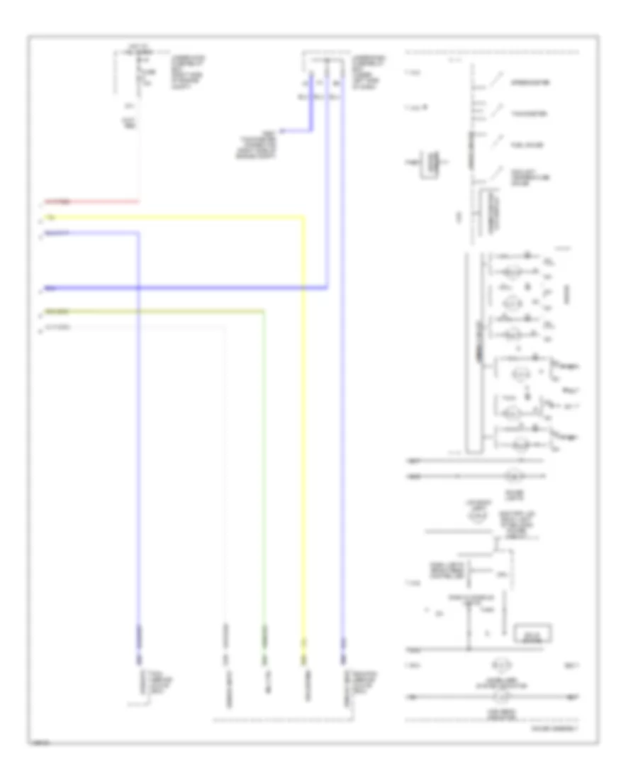
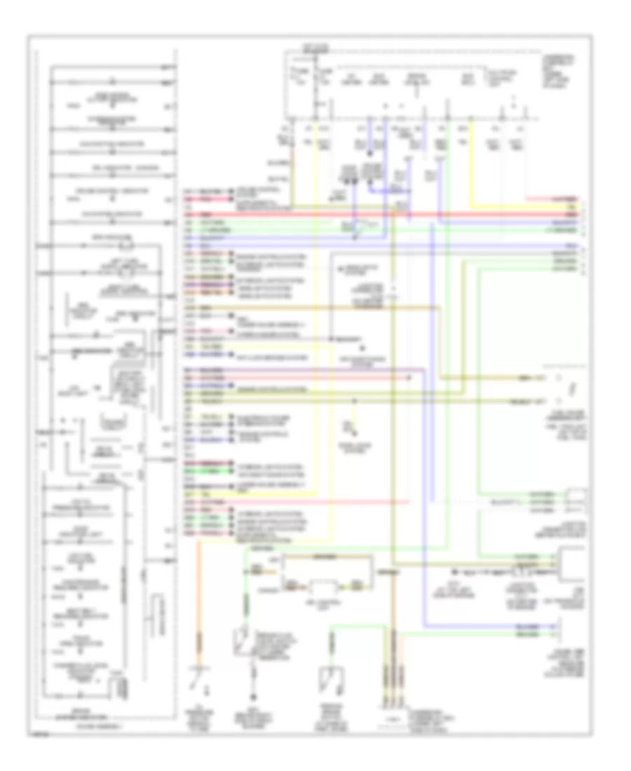
Instrument Cluster Wiring Diagram, DX, GX (1 of 2) for Honda Civic Hybrid 2004

List of elements for Instrument Cluster Wiring Diagram, DX, GX (1 of 2) for Honda Civic Hybrid 2004:
- (canada)
- (dx)
- (gx)
- (not used)
- (under gauge assembly) g501
- A10
- A11
- A12
- A13
- A14
- A15
- A16
- A17
- A18
- A19
- A20
- A21
- A22
- Abs indicator (except dx)
- Abs indicator circuit (except dx)
- Anti-lock brakes system
- B10
- B11
- B12
- B13
- B14
- B15
- B16
- B17
- B18
- B19
- B20
- B21
- B22
- Beeper
- Beeper (dx)
- Beeper (gx)
- Brake fluid level switch (on master cylinder reservoir)
- Brake level sw
- Bus (meter)
- Bus (sefmj)
- Canada
- Charging system indicator
- Cpu
- Cruise control indicator (except dx)
- Cruise control system
- Cvt
- Door locks system
- Drive circuit
- Drl control unit
- Drl indicator
- E10
- Engine controls system
- Except cvt
- Except gx
- Exterior lights system
- Fuel gauge sending unit
- Fuel tank unit (on top of fuel tank)
- Fuse 10a
- Fuse 7.5a
- G101 (middle of engine)
- G301 (behind left side of front bumper)
- G551 (under front passenger's seat)
- Gauge assembly
- Headlights system
- Hot in on or start
- Ig1 (meter)
- Immobilizer control unit receiver (in steering column cover)
- Interior lights system
- Junction connector c102 (behind glove compt)
- Junction connector c103 (on cylinder head cover)
- Junction connector c104 (on cylinder head cover)
- K10
- Left turn signal indicator
- Low fuel indicator
- Low oil pressure indicator
- Maintenance required indicator
- Malfunction indicator
- Multiplex control unit
- O11
- Oil pressure switch (near oil filter)
- Parking brake & brake system indicator
- Parking brake switch (at base of park lever)
- Pnk
- Power circuit
- Red
- Right turn signal indicator
- Seat belt reminder indicator
- Side air bag cut-off indicator (except dx)
- Srs indicator
- Srs indicator circuit
- Switch trip/reset
- Trunk open indicator
- Under-dash fuse/relay box (under left side of dash)
- Usa
- Vss (except cvt) (on transmission housing)
- Washer level indicator (canada)
- Wiper/ washer system
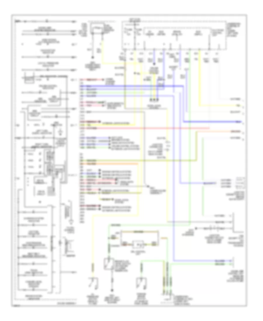
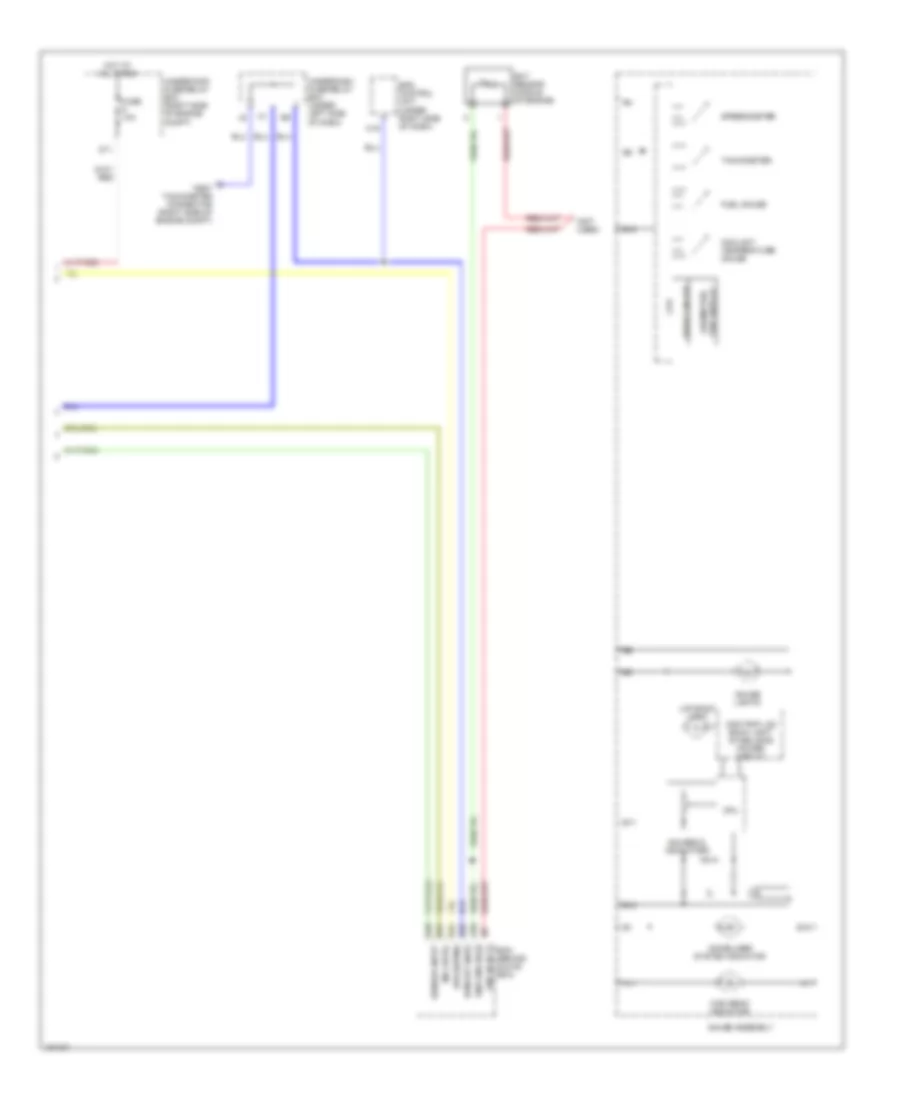
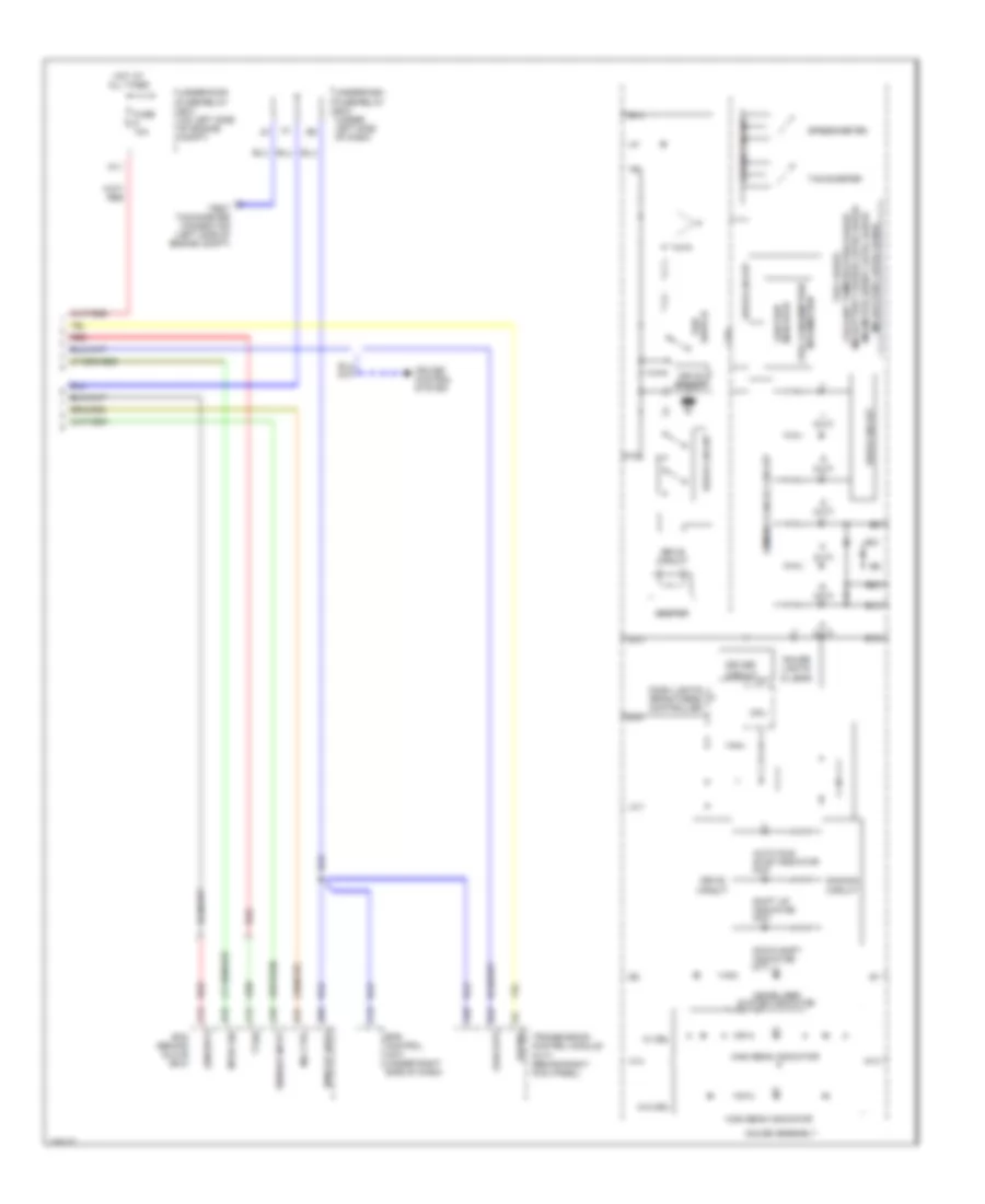
Instrument Cluster Wiring Diagram, DX, GX (2 of 2) for Honda Civic Hybrid 2004
List of elements for Instrument Cluster Wiring Diagram, DX, GX (2 of 2) for Honda Civic Hybrid 2004:
- (vssout)
- A12
- A13
- A16
- A18
- B10
- B11
- B16
- B17
- B18
- B22
- Bus (sefmj)
- Coolant temperature gauge
- Cpu
- D11
- Dash & console lights
- Dash lights brightness controller
- Dimming circuit
- Drive circuit
- Driver
- Driver circuit
- E24
- E25
- E26
- E31
- Ecm/pcm (behind glove box)
- Fuel gauge
- Fuse 10a
- Gauge assembly
- Gauge lights
- High beam indicator
- Hot at all times
- Immobilizer system indicator
- Lcd back light
- Mil ctrl
- Odo/trip lcd back light stabilizing power circuit
- Odometer/trip lcd display
- Pcm (behind glove box)
- Rpm out (nep)
- Sensor input
- Solid state
- Speedometer
- Tachometer
- Test tachometer connector (right side of engine compt)
- Under-dash fuse/relay box (under left side of dash)
- Under-hood fuse/relay box (right side of engine compt)
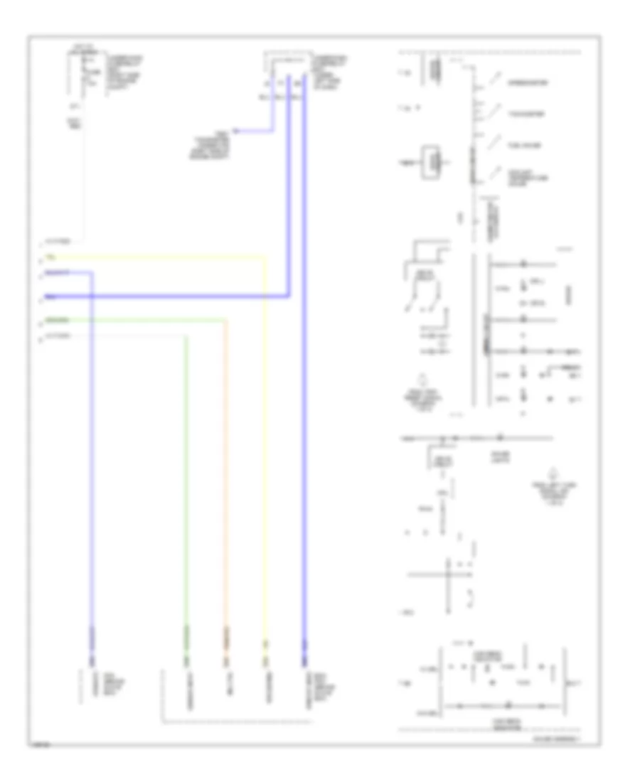
Instrument Cluster Wiring Diagram, EX, HX, LX (1 of 2) for Honda Civic Hybrid 2004
List of elements for Instrument Cluster Wiring Diagram, EX, HX, LX (1 of 2) for Honda Civic Hybrid 2004:
- (canada)
- (not used)
- (under gauge assembly)
- A10
- A11
- A12
- A13
- A14
- A15
- A16
- A17
- A18
- A19
- A20
- A21
- A22
- Abs indicator
- Abs indicator circuit
- Anti-lock brakes system
- B10
- B11
- B12
- B13
- B14
- B15
- B16
- B17
- B18
- B19
- B20
- B21
- B22
- Beeper
- Brake fluid level switch (on master cylinder reservoir)
- Brake level sw
- Brake system indicator
- Bus (meter)
- Bus (sefmj)
- Canada
- Charging system indicator
- Circuit
- Cpu
- Cruise control indicator
- Cruise control system
- Cvt
- Dimmer circuit
- Door locks system
- Drive circuit
- Drl control unit
- Drl indicator
- E10
- Engine controls system
- Except cvt
- Exterior lights system
- Fuel gauge sending unit
- Fuel tank unit (on top of fuel tank)
- Fuse 10a
- Fuse 7.5a
- G101 (middle of engine)
- G301 (behind left side of front bumper)
- G501
- G551 (under front passenger's seat)
- Gauge assembly
- Headlights system
- Hot in on or start
- Ig1 (meter)
- Immobilizer control unit receiver (in steering column cover)
- Immobilizer system indicator
- Interior lights system
- Junction connector c102 (behind glove compt)
- Junction connector c103 (on cylinder head cover)
- Junction connector c104 (on cylinder head cover)
- K10
- Lcd/dual diameter circuit
- Left turn signal indicator
- Low fuel indicator
- Low oil pressure indicator
- Maintenance required indicator
- Malfunction indicator
- Multiplex control unit
- O11
- Oil pressure switch (near oil filter)
- Parking brake switch (at base of park lever)
- Pnk
- Pointer diameter
- Power circuit
- Red
- Right turn signal indicator
- Seat belt reminder indicator
- Side air bag cut-off indicator
- Srs indicator
- Srs indicator circuit
- Switch trip/reset
- To cpu (diagram 2 of 2)
- To gauge lights (diagram 2 of 2)
- Trunk open indicator
- Under-dash fuse/relay box (under left side of dash)
- Usa
- Vss (except cvt) (on transmission housing)
- Washer level indicator (canada)
- Wiper/ washer system
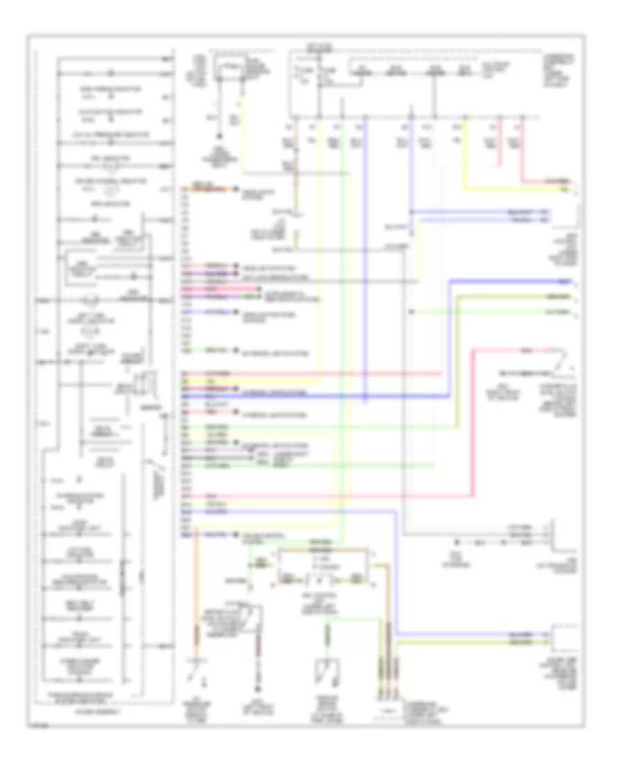
Instrument Cluster Wiring Diagram, EX, HX, LX (2 of 2) for Honda Civic Hybrid 2004
List of elements for Instrument Cluster Wiring Diagram, EX, HX, LX (2 of 2) for Honda Civic Hybrid 2004:
- (or l)
- (or s)
- (vssout)
- A14
- A18
- B10
- B12
- B13
- B17
- B18
- Bus (sefmj)
- Coolant temperature gauge
- Cpu
- D11
- Dimming circuit
- Drive circuit
- Driver
- Driver circuit
- E24
- E25
- E26
- E31
- Ecm/ pcm (behind glove box)
- From left turn signal ind (diagram 1 of 2)
- From trip/ reset signal (diagram 1 of 2)
- Fuel gauge
- Fuse 10a
- Gauge assembly
- Gauge lights
- High beam indicator
- Hot at all times
- Mil ctrl
- Odometer/trip lcd display
- Pcm (behind glove box)
- Rpm out (nep)
- Sensor input
- Speedometer
- Tachometer
- Test tachometer connector (right side of engine compt)
- Under-dash fuse/relay box (under left side of dash)
- Under-hood fuse/relay box (right side of engine compt)
- W/ drl
- W/o drl
Instrument Cluster Wiring Diagram, Hatchback (1 of 2) for Honda Civic Hybrid 2004
List of elements for Instrument Cluster Wiring Diagram, Hatchback (1 of 2) for Honda Civic Hybrid 2004:
- (under right side of dash)
- A10
- A11
- A12
- A13
- A14
- A15
- A16
- A17
- A18
- A19
- A20
- A21
- A22
- Abs indicator
- Abs indicator circuit
- Anti-lock brake system
- B canada
- B10
- B11
- B12
- B13
- B14
- B15
- B16
- B17
- B18
- B19
- B20
- B21
- B22
- Beeper
- Brake fluid level switch (on master cylinder reservoir)
- Bus (brake)
- Bus (ecu)
- Bus (meter)
- Charging system indicator
- Cpu
- Cruise control indicator
- Cruise control system
- Door indicator light
- Drive circuit
- Drl control unit (under left side of dash)
- Drl indicator
- E10
- Eps control unit (under right side of dash)
- Eps indicator
- Exterior lights system
- Fuel gauge sending unit
- Fuel tank unit (on top of fuel tank)
- Fuse 10a
- Fuse 7.5a
- G101 (top of engine)
- G201 (right front of vehicle)
- G301 (left front of vehicle)
- G502
- G551 (under passenger's seat)
- Gauge assembly
- Headlights system
- Headlights system (canada)
- Hot in on or start
- Ig1 (meter)
- Immobilizer control unit- receiver (in steering column cover)
- Interior lights system
- J/c c104 (on cylinder head cover)
- K10
- Left turn signal indicator
- Low fuel indicator
- Low oil pressure indicator
- Maintenance required indicator
- Malfunction indicator
- Multiplex control unit
- Oil pressure switch (near oil filter)
- Parking brake & brake system indicator
- Parking brake switch (at base of park lever)
- Pnk
- Power circuit
- Red
- Right turn signal indicator
- Seat belt reminder
- Side airbag indicator
- Srs indicator
- Srs indicator circuit
- Switch trip/reset
- Trunk indicator light
- Underdash fuse/relay box (under left side of dash)
- Usa a
- Vss (on transaxle housing)
- Washer fluid level switch (canada) (behind left side of front bumper)
- Wiper/washer indicator (canada)
Instrument Cluster Wiring Diagram, Hatchback (2 of 2) for Honda Civic Hybrid 2004
List of elements for Instrument Cluster Wiring Diagram, Hatchback (2 of 2) for Honda Civic Hybrid 2004:
- (not used)
- A10
- A11
- A18
- B11
- B12
- B18
- B19
- Bus (sefmj)
- C19
- Coolant temperature gauge
- Cpu
- D11
- Drive circuit
- E24
- E26
- E31
- Ecm (behind glove box)
- Ect sensor (middle of engine)
- Eps control unit (under right side of dash)
- Fuel gauge
- Fuse 10a
- Gauge assembly
- Gauge lights
- Gauges & indicators
- High beam indicator
- Hot at all times
- Immobilizer system indicator
- Lcd back light
- Mil cntrl
- Odo/trip lcd back light stabilizing power circuit
- Odometer/ trip display
- Rpm out (nep)
- Sensor input
- Sns gnd (sg2)
- Sns in (ect)
- Speedometer
- Tachometer
- Test tachometer connector (right side of engine compt)
- Underdash fuse/relay box (under left side of dash)
- Underhood fuse/relay box (right side of engine compt)
Instrument Cluster Wiring Diagram, Hybrid (1 of 2) for Honda Civic Hybrid 2004
List of elements for Instrument Cluster Wiring Diagram, Hybrid (1 of 2) for Honda Civic Hybrid 2004:
- (canada)
- (not used)
- (under gauge assembly) g501
- A10
- A11
- A12
- A13
- A14
- A15
- A16
- A17
- A18
- A19
- A20
- A21
- A22
- Abs indicator
- Abs indicator circuit
- Air conditioning system
- Anti-lock brakes system
- B10
- B11
- B12
- B13
- B14
- B15
- B16
- B17
- B18
- B19
- B20
- B21
- B22
- Brake fluid level switch (on master cylinder reservoir)
- Brake level sw
- Brake system indicator
- Bus (ecu)
- Bus (meter)
- Canada
- Charging system indicator
- Cpu
- Cruise control indicator
- Cruise control system
- Cvt
- Door indicator light
- Door locks system
- Drive circuit
- Drl control unit
- Drl indicator
- E10
- Electronic power steering system
- Engine controls system
- Eps indicator
- Exterior lights system
- Exterior lights system (canada)
- Fuel gauge sending unit
- Fuel tank unit (on top of fuel tank)
- Fuse 10a
- Fuse 7.5a
- G101 (at top left side of engine)
- G201 (behind right side of front bumper)
- G501 (under gauge assembly)
- Gauge assembly
- Headlights system
- Hot in on or start
- Ig1 (meter)
- Ima system indicator
- Immobilizer control unit receiver (in steering column cover)
- Interior lights system
- Junction connector c106 (behind glove box)
- Junction connector c110 (on center of engine)
- Junction connector c111 (on center of engine)
- K10
- Lcd back light
- Left turn signal indicator
- Low fuel indicator
- Low oil pressure indicator
- M/t
- Maintenance required indicator
- Malfunction indicator
- Multiplex control unit
- O11
- Odo/trip lcd circuit back light stabilizing power circuit
- Oil pressure switch (near oil filter)
- Parking brake switch (at base of park lever)
- Pnk
- Power circuit
- Red
- Right turn signal indicator
- Rxd
- Seat belt reminder indicator
- Side air bag cut-off indicator
- Srs indicator
- Srs indicator circuit
- Trunk open indicator
- Txd
- Underdash fuse/relay box (under left side of dash)
- Usa
- Vss (m/t) (on transaxle housing)
- Washer fluid level indicator (canada)
- Wiper/washer system
Instrument Cluster Wiring Diagram, Hybrid (2 of 2) for Honda Civic Hybrid 2004
List of elements for Instrument Cluster Wiring Diagram, Hybrid (2 of 2) for Honda Civic Hybrid 2004:
- (cvt)
- (engrdy)
- (sefmj)
- (vss out)
- A13
- A14
- A16
- A17
- A18
- A28
- Auto idle stop indicator (m/t)
- B10
- B13
- B14
- B16
- B19
- B20
- B21
- B22
- Beeper
- C12
- C13
- C19
- Coolant temperature gauge
- Cpu
- Cruise control system
- D (cvt)
- D11
- Dash lights brightness controller
- Dimming cancel circuit
- Dimming circuit
- Down shift indicator (m/t)
- Drive circuit
- Driver circuit
- E19
- E26
- E31
- Ecm (behind glove box)
- Eps control unit (under right side of dash)
- Fuel consumption information
- Fuel gauge
- Fuse 10a
- Gauge assembly
- Gauge lights (5 leds)
- High beam indicator
- Hot at all times
- Ima battery charge level gauge
- Ima battery level gauge
- Ima motor assist level gauge
- Immobilizer system indicator
- Mil ctrl
- Mtra sig
- Odo/trip indicator
- P (cvt)
- R (cvt)
- Red
- Rpm out (nep)
- Sensor input
- Shift up indicator (m/t)
- Speedometer
- Switch trip
- Tachometer
- Test tachometer connector (left side of engine compt)
- Ti sig
- Transmission control module (cvt) (behind right kick panel)
- Underdash fuse/relay box (under left side of dash)
- Underhood fuse/relay box (on left side of engine compt)
- W/ drl
- W/o drl