INSTRUMENT CLUSTER
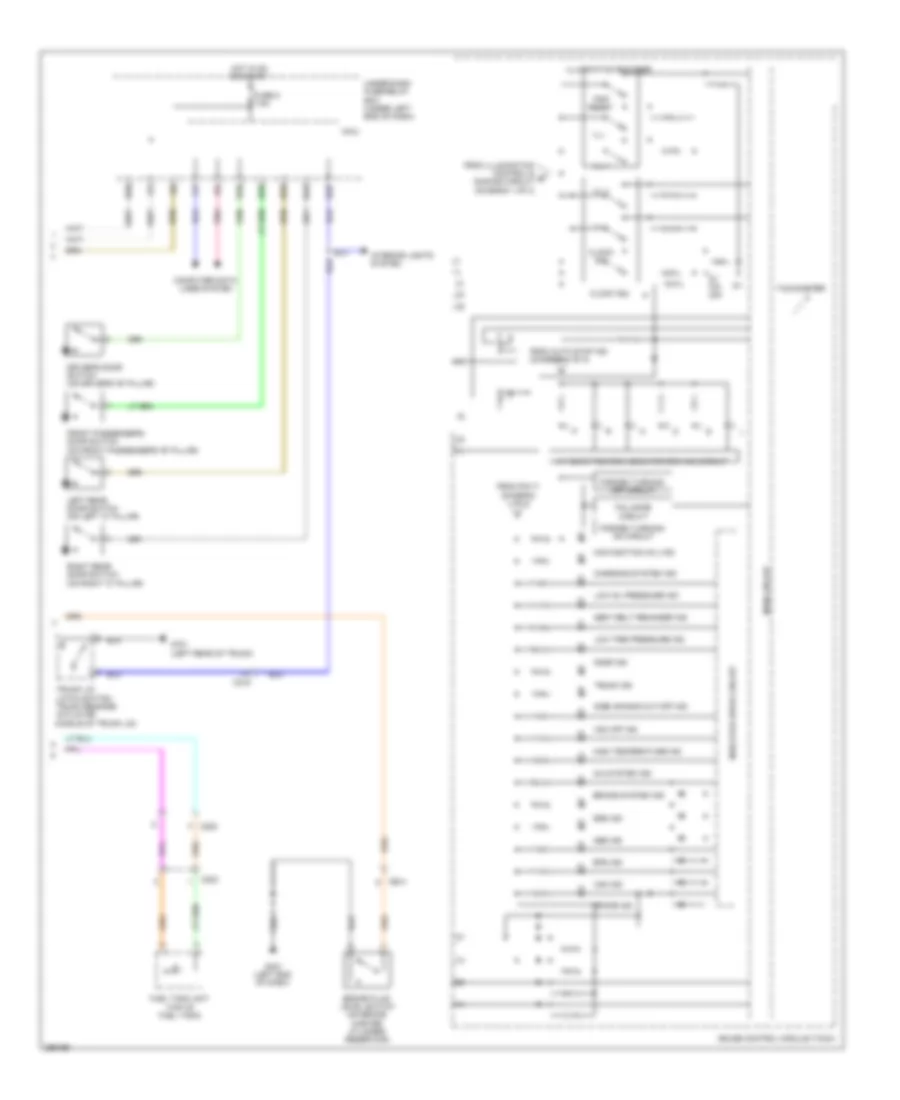
Instrument Cluster Wiring Diagram, Except Hybrid (1 of 2) for Honda Civic Hybrid 2013

List of elements for Instrument Cluster Wiring Diagram, Except Hybrid (1 of 2) for Honda Civic Hybrid 2013:
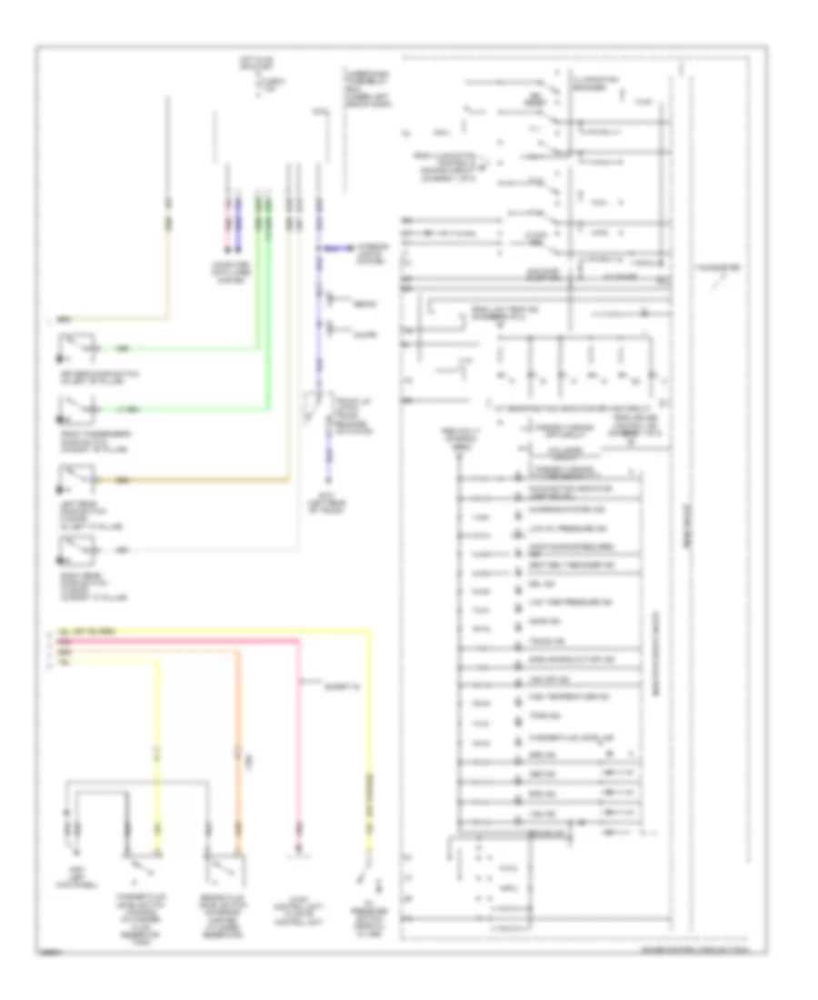
Instrument Cluster Wiring Diagram, Except Hybrid (2 of 2) for Honda Civic Hybrid 2013
List of elements for Instrument Cluster Wiring Diagram, Except Hybrid (2 of 2) for Honda Civic Hybrid 2013:
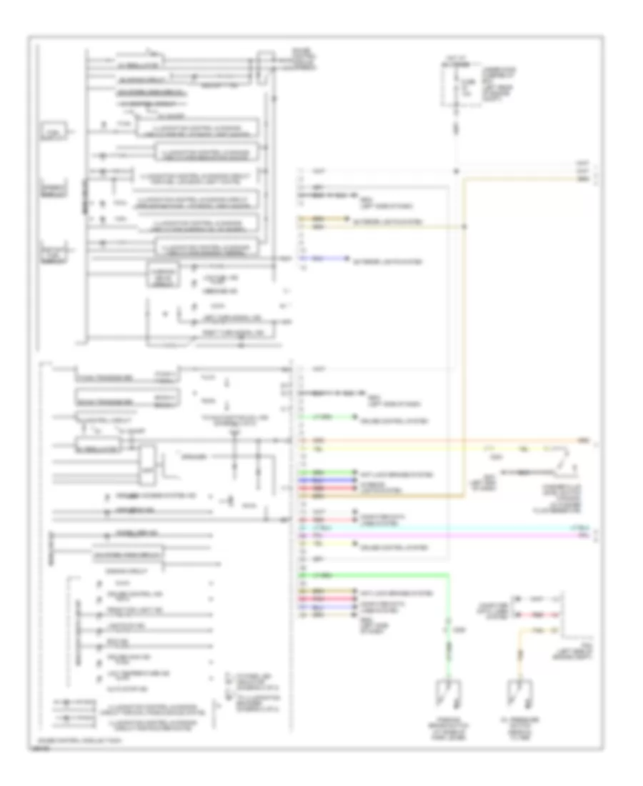
Instrument Cluster Wiring Diagram, Hybrid (1 of 2) for Honda Civic Hybrid 2013
List of elements for Instrument Cluster Wiring Diagram, Hybrid (1 of 2) for Honda Civic Hybrid 2013:
Instrument Cluster Wiring Diagram, Hybrid (2 of 2) for Honda Civic Hybrid 2013
List of elements for Instrument Cluster Wiring Diagram, Hybrid (2 of 2) for Honda Civic Hybrid 2013: