INSTRUMENT CLUSTER
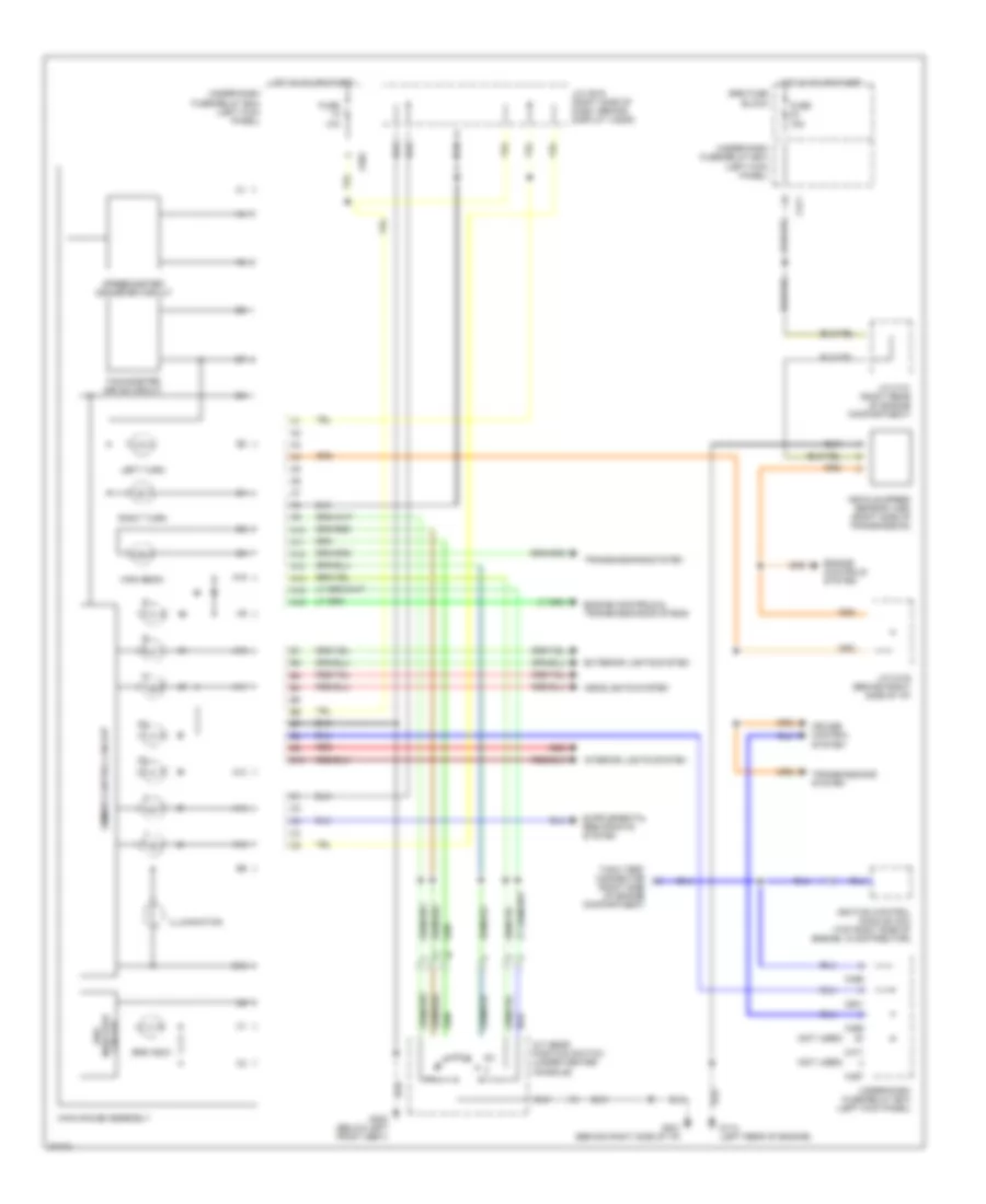
Main Gauge Assembly Wiring Diagram, with Electro-Luminescent Gauges (1 of 2) for Honda Prelude S 1996

List of elements for Main Gauge Assembly Wiring Diagram, with Electro-Luminescent Gauges (1 of 2) for Honda Prelude S 1996:
- (not used)
- 10a
- Battery
- C422
- C601
- Dc/ac inverter (left side of main gauge assembly)
- Dimmer control circuit
- Dimming circuit
- Dimming input
- Dimming output
- Engine controls system, transmissions system
- Exterior lights system
- Fuse
- Fuse 43 clock/radio
- G201 (left side of i/p)
- G302 (below center console)
- Ground
- H10
- Headlights system
- High beam
- Hot at all times
- Hot in on or start
- Ignition
- Illumination
- Interior lights system
- Inverter
- J/c c419 (behind right i/p)
- J/c c619 (right side of dash, behind display visor)
- Left turn
- Main gauge assembly
- Pnk
- R10
- R11
- R12
- R13
- R14
- Red
- Right turn
- Speed sig
- Speedo heater
- Speedo thermistor
- Speedometer crt
- Speedometer/odometer/ tachometer circuit
- Spped sig
- Srs indic
- Srs indicator circuit
- Sub guage assembly
- T10
- Tach heater
- Tachometer crt
- Transmissions system
- Under-dash fuse/relay box (left kick panel)
- Under-hood fuse/relay box (right rear of engine compartment)
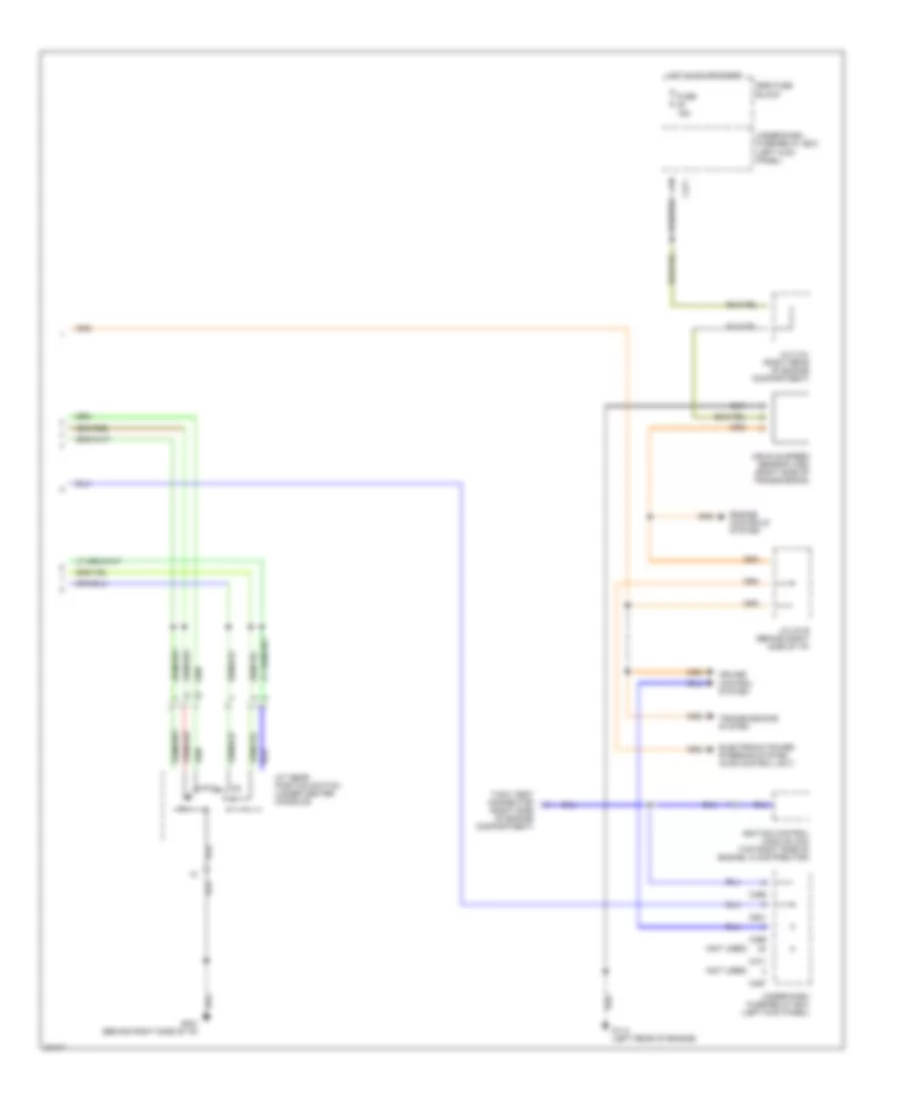
Main Gauge Assembly Wiring Diagram, with Electro-Luminescent Gauges (2 of 2) for Honda Prelude S 1996
List of elements for Main Gauge Assembly Wiring Diagram, with Electro-Luminescent Gauges (2 of 2) for Honda Prelude S 1996:
- (not used)
- 15a
- A/t gear position switch (under center console)
- C467
- C469
- C471
- C601
- Cruise control system
- Electronic power steering system (4ws control unit)
- Engine controls system
- Fuse
- G114 (left rear of engine)
- G201 (behind right side of i/p)
- Hot in on or start
- Ignition control module (icm) (top right side of engine, in distributor)
- J/c c131 (right rear of engine compartment)
- J/c c419 (behind right side of i/p)
- Srs fuse block
- Tach test connector (right side of engine compartment)
- Transmissions system
- Under-dash fuse/relay box (left kick panel)
- Vehicle speed sensor (vss) (right side of transmission)
Main Gauge Assembly Wiring Diagram, without Electro-Luminescent Gauges for Honda Prelude S 1996
List of elements for Main Gauge Assembly Wiring Diagram, without Electro-Luminescent Gauges for Honda Prelude S 1996:
- (not used)
- 10a
- 15a
- A/t gear position switch (under center console)
- A10
- A11
- A12
- A13
- A14
- A15
- A16
- B10
- C467
- C469
- C471
- C601
- Cruise control system
- Dimmer control circuit
- Engine controls & transmissions systems
- Engine controls system
- Exterior lights system
- Fuse
- G114 (left rear of engine)
- G201 (behind right side of i/p)
- G300 (below left front seat)
- Headlights system
- High beam
- Hot in on or start
- Ignition control module (icm) (top right side of engine, in distributor)
- Illumination
- Interior lights system
- J/c c131 (right rear of engine compartment)
- J/c c419 (behind right side of i/p)
- J/c c619 (right side of dash, behind display visor)
- Left turn
- Main gauge assembly
- Red
- Right turn
- Speedometer/ odometer circuit
- Srs fuse block
- Srs indic
- Srs indicator circuit
- Tach test connector (right side of engine compartment)
- Tachometer drive circuit
- Transmissions system
- Under-dash fuse/relay box (left kick panel)
- Vehicle speed sensor (vss) (right side of transmission)
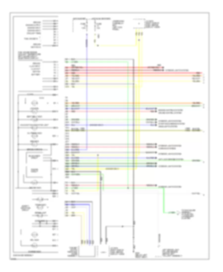
Sub Gauge Assembly Wiring Diagram (1 of 2) for Honda Prelude S 1996
List of elements for Sub Gauge Assembly Wiring Diagram (1 of 2) for Honda Prelude S 1996:
- (1995) (1996)
- (canada only)
- 10a
- 7.5a
- Abs indic
- Anti-lock brakes system
- Battery
- Brake lamp
- Brake warning
- Bulb check circuit
- C601
- Charge indic
- Clock
- Coolant temp
- Cruise control system
- Cruise indic
- D10
- Dimming circuit
- Dimming input
- Dimming output
- Door indic
- Drl indic
- E10
- E11
- E12
- E13
- E14
- E15
- E16
- E17
- E18
- E19
- E20
- E21
- E22
- E23
- E24
- E25
- E26
- E27
- E28
- E29
- E30
- Engine controls system
- Fuel gauge in
- Fuel gauge/ engine coolant temperature (ect) gauge circuit (electronic display)
- Fuse
- G300 (below left front seat)
- Ground
- Headlights system
- Hot in on or start
- Hot in start
- Ignition
- Ignition in
- Illum input
- Illum out
- Interior lights system
- J/c c619 (right side of dash, behind display visor)
- Left brake light failure sensor (behind left taillight assembly)
- Low fuel
- Malfunction indicator light
- Oil press indic
- Red
- Safety indicator circuit
- Seat belt indic
- Starting/charging system
- Sub gauge assembly
- Time set switch (near sub- gauge assembly)
- To main gauge assembly (w/ electro- luminescent cluster)
- Trunk indic
- Under-dash fuse/relay box (left kick panel)
- Warning systems
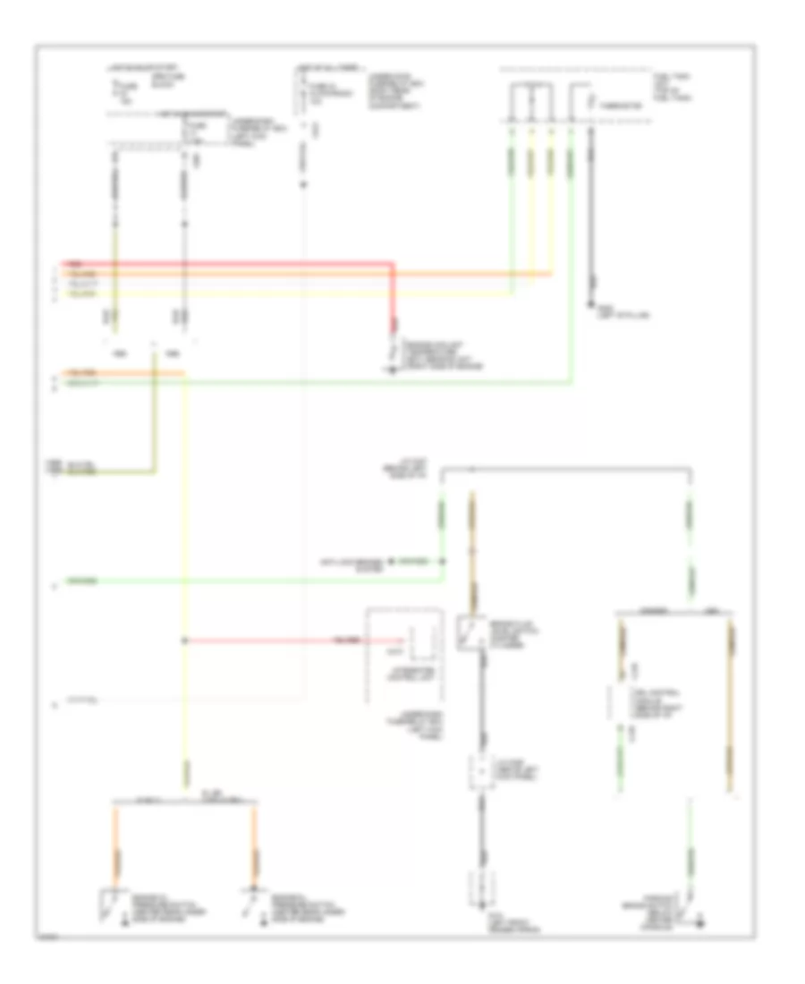
Sub Gauge Assembly Wiring Diagram (2 of 2) for Honda Prelude S 1996
List of elements for Sub Gauge Assembly Wiring Diagram (2 of 2) for Honda Prelude S 1996:
- (1995) (1996)
- 10a
- 15a
- 7.5a
- Anti-lock brakes system
- Brake fluid level switch (master cylinder)
- C418
- C422
- C473
- C601
- Canada
- Drl control module (behind right side of i/p)
- Engine coolant temperature (ect) sending unit (right side of engine)
- Engine oil pressure switch (center rear under- side of engine)
- Fuel tank unit (top of fuel tank)
- Fuse
- Fuse 43 clock/radio
- G101 (left front fender apron)
- G308 (left 'b' pillar)
- Hot at all times
- Hot in on or start
- Integrated control unit
- J/c c326 (above left kick panel)
- J/c c447 (behind left side of i/p)
- Parking brake switch (below center console)
- Red
- S only
- Srs fuse block
- Si, sr, vtec & sr-v
- Thermistor
- Under-dash fuse/relay box (left kick panel)
- Under-hood fuse/relay box (right rear of engine compartment)
- Usa