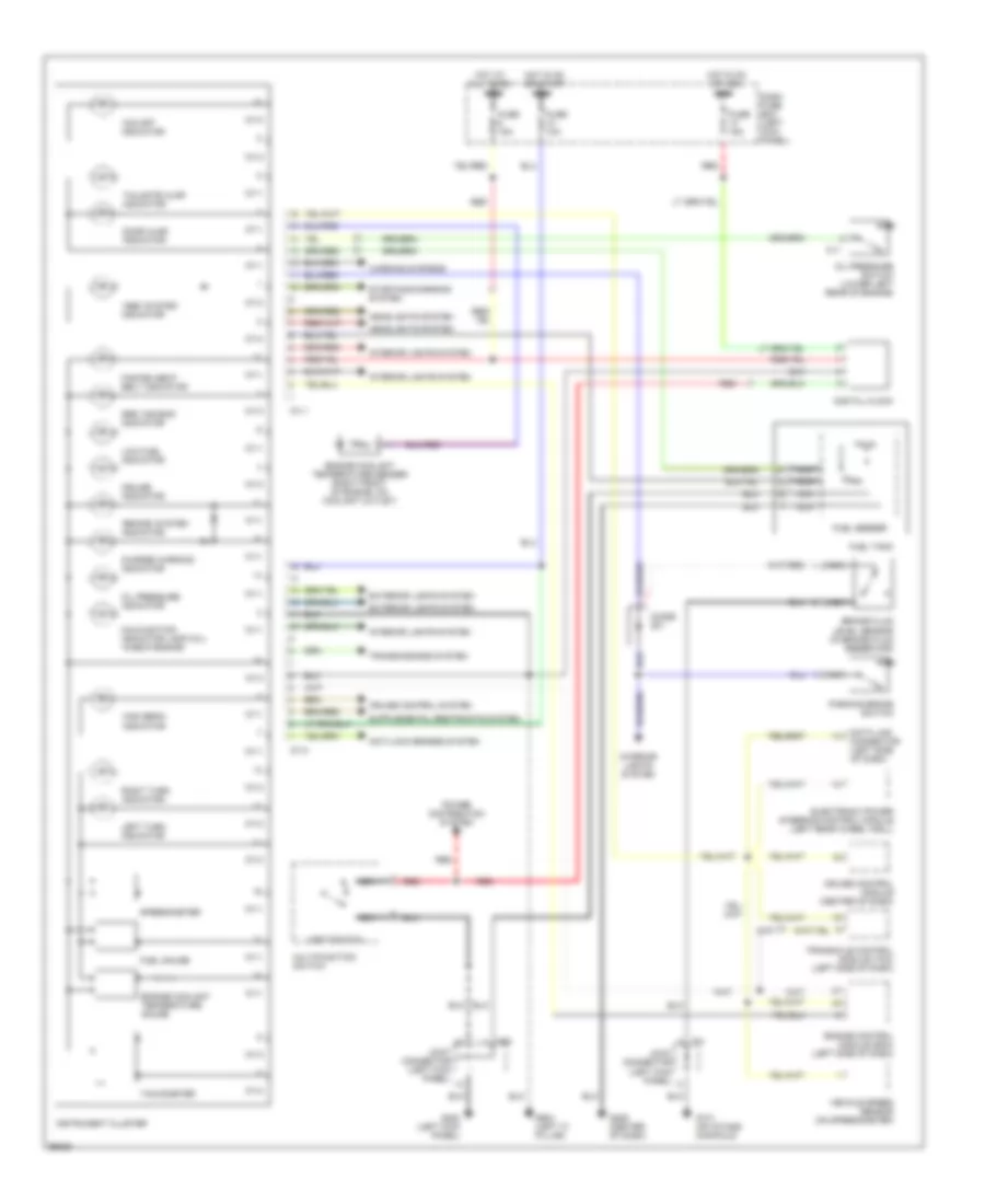
INSTRUMENT CLUSTER
Instrument Cluster Wiring Diagram for Hyundai Tiburon FX 1997
List of elements for Instrument Cluster Wiring Diagram for Hyundai Tiburon FX 1997:
- "abs" system indicator
- "brake" system indicator
- "o/d off" indicator
- Anti-lock brakes system
- Brake fluid level sensor (in brake fluid reservoir)
- C11
- C31
- Charge warning indicator
- Cruise control module (center of dash)
- Cruise control system
- Cruise indicator
- Dash fuse box (left kick panel)
- Data link connector (left side of dash)
- Digital clock
- Diode z01
- Door ajar indicator
- Electronic power steering control module (left rear wheel well)
- Engine control module (ecm) (left side of dash)
- Engine coolant temperature gauge
- Engine coolant temperature sender (right front of engine, on coolant outlet)
- Exterior lights system
- Fasten seat belt indicator
- Fuel gauge
- Fuel sender
- Fuel tank
- Fuse 10a
- Fuse 15a
- G131 (on intake manifold)
- G200 (left kick panel)
- G206 (center of dash)
- G904 (left "c" pillar)
- Headlights system
- High beam indicator
- Hot at all times
- Hot in on or acc
- Hot in on or start
- I01-1
- I01-2
- Instrument cluster
- Interior lights system
- Joint connector (left kick panel)
- Left turn indicator
- Light switch
- Low fuel indicator
- M58
- Malfunction indicator lamp (mil) "check engine"
- Multifunction switch
- Nca
- Oil pressure indicator
- Oil pressure switch (lower left rear of engine)
- Parking brake switch
- Power distribution system
- Red
- Right turn indicator
- Speedometer
- Srs "air bag" indicator
- Starting/charging system
- Tachometer
- Tailgate ajar indicator
- Transaxle control module (tcm) (left side of dash)
- Transmissions system
- Vehicle speed sensor (on speedometer)
- Warning systems
 English