INSTRUMENT CLUSTER
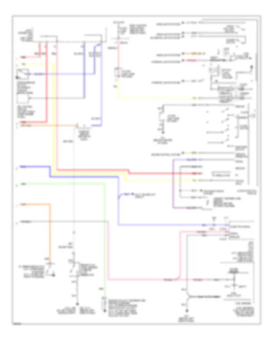
Instrument Cluster Wiring Diagram (1 of 2) for Hyundai Tiburon GS 2008

List of elements for Instrument Cluster Wiring Diagram (1 of 2) for Hyundai Tiburon GS 2008:
Instrument Cluster Wiring Diagram (2 of 2) for Hyundai Tiburon GS 2008
List of elements for Instrument Cluster Wiring Diagram (2 of 2) for Hyundai Tiburon GS 2008:
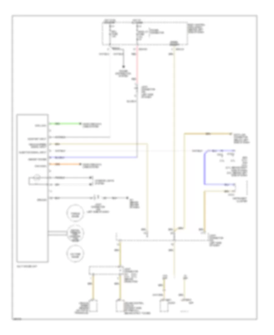
Multi-Gauge Unit Wiring Diagram for Hyundai Tiburon GS 2008
List of elements for Multi-Gauge Unit Wiring Diagram for Hyundai Tiburon GS 2008: