INSTRUMENT CLUSTER
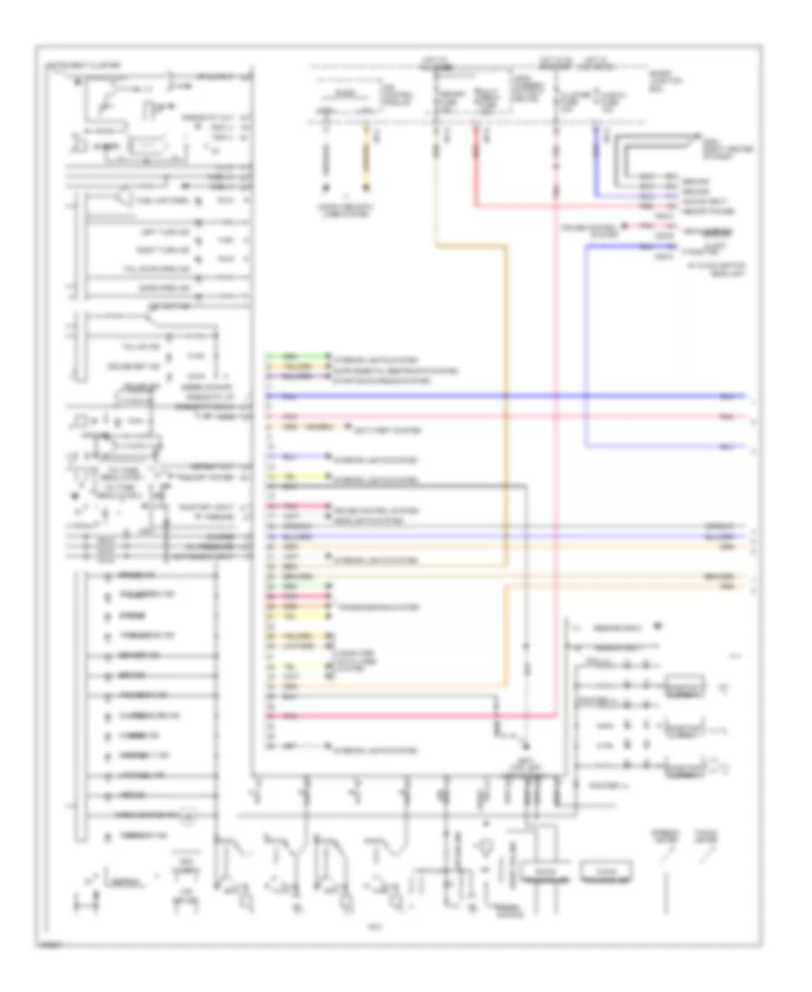
Instrument Cluster Wiring Diagram, with Conventional Cluster (1 of 2) for Hyundai Veloster 2013

List of elements for Instrument Cluster Wiring Diagram, with Conventional Cluster (1 of 2) for Hyundai Veloster 2013:
- (+)
- (-)
- 4p output
- A/v & navigation head unit
- Abs ind
- Acc/on input
- Active eco input
- Air bag ind
- Anti-theft system
- Audio 2 fuse 10a
- B-can
- Bag air
- Brake ind
- Buzzer
- C-can
- Charge
- Charge ind
- Check engine ind
- Clock
- Cluster fuse 10a
- Computer data lines system
- Cruise control system
- Cruise ind
- Cruise set ind
- Dail ill
- Detent out
- Door open ind
- Driver
- Eco (green) ind
- Eeprom
- Eps ind
- Esc ind
- Esc off ind
- Fog front
- Front fog ind
- Fuel (+)
- Fuel (-)
- Fuel cap open ind
- Gm01 (top left side of dash)
- Gm04 (right center of dash)
- Green dimming
- Ground
- Headlights system
- High
- High beam ind
- Hot at all times
- Hot in acc or on
- Hot in on or start
- I/p-c
- I/p-e
- I/p-g
- I/p-h
- Ill (+)
- Immo
- Immo ind
- Instrument cluster
- Interior lights system
- Ips control module
- Key out ind
- Lcd
- Lcd ill
- Leak current autocut device
- Left turn ind
- Low
- Low fuel ind
- M02-a
- M02-b
- Mcu
- Memory fuse 10a
- Memory power
- Multi media fuse 15a
- Odo
- Oil pressure
- Oil pressure ind
- On/start input
- Out d
- Out n
- Out p
- Out r
- P position
- P/brake
- Pnk
- Pointer ill
- Red
- Rheostat down
- Rheostat out
- Rheostat up
- Right turn ind
- Seat belt ind
- Sensor gnd 1
- Sensor gnd 2
- Smart junction box
- Speedo- meter
- Starting/charging system
- Tacho- meter
- Tail gate open ind
- Tail on ind
- Temp high ind
- Tpms tread ind
- Transceiver
- Transmissions system
- Trip (+)
- Trip (-)
- Vehicle sp sig
- Voltage regulator
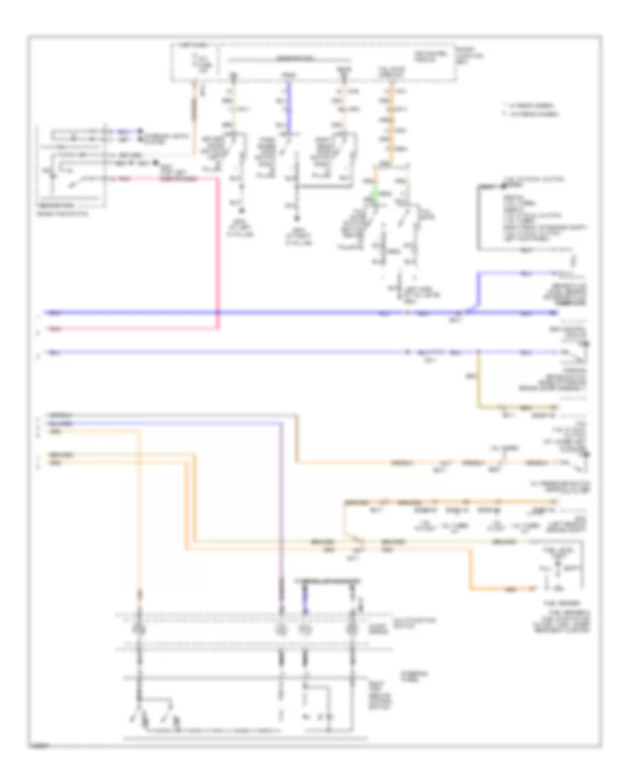
Instrument Cluster Wiring Diagram, with Conventional Cluster (2 of 2) for Hyundai Veloster 2013
List of elements for Instrument Cluster Wiring Diagram, with Conventional Cluster (2 of 2) for Hyundai Veloster 2013:
- "c" pillar)
- (+)
- (-)
- (1.6l w/o dual clutch) gggg04
- (left side of tail gate) gr01
- 1.6l turbo
- 1.6l turbo a/t
- 1.6l turbo m/t
- 1.6l w/ dct
- 1.6l w/o dct
- Brake fluid level sensor (on brake fluid reservoir)
- Clock spring
- Crash pad switch
- Door switch
- Dri
- Driver door switch (left "b" pillar)
- Ecm (left rear of engine compt)
- Eco switch
- Ee31
- Ef11
- Eggd-mk
- Eggd-tb
- Eggg-mk
- Eggt-aa
- Eggt-mk
- Em11
- Empty
- Esc control module
- Fuel level float
- Fuel sender
- Fuel sender & fuel pump motor (in fuel tank, under rear seat cushion)
- Full
- Gf03 (at left
- Gf04 (at right
- Gggt04 (1.6l turbo) gggd13 (1.6l w/ dual clutch) (1.6l turbo: right front of engine compt) (1.6l w/ dual clutch: left kick panel)
- Gm01 (top left side of dash)
- Hot in on
- I/p-b
- I/p-c
- I/p-g
- Ig 2 fuse 10a
- Ill
- Ind
- Interior lights system
- Ips control module
- M01-r
- Mf11
- Mf21
- Mf61
- Multi-function switch
- Nca
- Oil pressure switch (near oil filter)
- Parking brake switch (base of parking brake lever assembly)
- Pass
- Pass- enger door switch (right "b" pillar)
- Pnk
- Rear rh
- Reset
- Right rear door switch (right "c" pillar)
- Right trip remote control switch
- Rr01
- Rr02
- Smart junction box
- Steering wheel
- Tail gate
- Tail gate open sw
- Tail gate switch (bottom center of tailgate)
- Tcm (1.6l w/ dual clutch) (at lower left "a" pillar)
- Trip
- Trip (+)
- Trip (-)
- W/ rear camera
- W/o rear camera
Instrument Cluster Wiring Diagram, with Super Vision (1 of 2) for Hyundai Veloster 2013
List of elements for Instrument Cluster Wiring Diagram, with Super Vision (1 of 2) for Hyundai Veloster 2013:
- (+)
- (-)
- 4p output
- A/v & navigation head unit
- Abs ind
- Acc/on input
- Active eco input
- Air bag ind
- Anti-theft system
- Audio 2 fuse 10a
- B-can
- Bag air
- Brake ind
- Buzzer
- C-can
- Charge
- Charge ind
- Check engine ind
- Clock
- Cluster fuse 10a
- Computer data lines system
- Constant current
- Cruise control system
- Cruise ind
- Cruise set ind
- Detent out
- Dial ill
- Door open ind
- Driver
- Eco (green) ind
- Eeprom
- Eps ind
- Esc ind
- Esc off ind
- Fog front
- Front fog ind
- Fuel (+)
- Fuel (-)
- Fuel cap open
- Gm01 (top left side of dash)
- Gm04 (right center of dash)
- Green dimming
- Ground
- Headlights system
- High
- High beam ind
- Hot at all times
- Hot in acc or on
- Hot in on or start
- I/p-c
- I/p-e
- I/p-g
- I/p-h
- Ill (+)
- Immo
- Immo ind
- Instrument cluster
- Interior lights system
- Ips control module
- Key out ind
- Lcd
- Leak current autocut device
- Left turn ind
- Low
- Low fuel ind
- M02-a
- M02-b
- Mcu
- Memory fuse 10a
- Memory power
- Multi media fuse 15a
- Odo
- Oil pressure
- Oil pressure ind
- On/start input
- Out d
- Out n
- Out p
- Out r
- P position
- P/brake
- Pnk
- Pointer ill
- Red
- Rheostat down
- Rheostat out
- Rheostat up
- Right turn ind
- Seat belt ind
- Sensor gnd 1
- Sensor gnd 2
- Smart junction box
- Speedo- meter
- Starting/charging system
- Tacho- meter
- Tail gate open ind
- Tail on ind
- Temp high ind
- Tpms tread ind
- Transceiver
- Transmissions system
- Trip (+)
- Trip (-)
- Vehicle sp sig
- Voltage regulator 1
- Voltage regulator 2
Instrument Cluster Wiring Diagram, with Super Vision (2 of 2) for Hyundai Veloster 2013
List of elements for Instrument Cluster Wiring Diagram, with Super Vision (2 of 2) for Hyundai Veloster 2013:
- "c" pillar)
- (+)
- (-)
- (1.6l w/o dual clutch) gggg04
- (left side of tail gate) gr01
- 1.6l turbo
- 1.6l turbo a/t
- 1.6l turbo m/t
- 1.6l w/ dct
- 1.6l w/o dct
- Brake fluid level sensor (on brake fluid reservoir)
- Clock spring
- Crash pad switch
- Door switch
- Dri
- Driver door switch (left "b" pillar)
- Ecm (left rear of engine compt)
- Eco switch
- Ee31
- Ef11
- Eggd-mk
- Eggd-tb
- Eggg-mk
- Eggt-aa
- Eggt-mk
- Em11
- Empty
- Esc control module
- Fuel level float
- Fuel sender
- Fuel sender & fuel pump motor (in fuel tank, under rear seat cushion)
- Full
- Gf03 (at left
- Gf04 (at right
- Gggt04 (1.6l turbo) gggd13 (1.6l w/ dual clutch) (1.6l turbo: right front of engine compt) (1.6l w/ dual clutch: left kick panel)
- Gm01 (top left side of dash)
- Hot in on
- I/p-b
- I/p-c
- I/p-g
- Ig 2 fuse 10a
- Ill
- Ind
- Interior lights system
- Ips control module
- M01-r
- Mf11
- Mf21
- Mf61
- Multi-function switch
- Nca
- Oil pressure switch (near oil filter)
- Parking brake switch (base of parking brake lever assembly)
- Pass
- Pass- enger door switch (right "b" pillar)
- Pnk
- Rear rh
- Reset
- Right rear door switch (right "c" pillar)
- Right trip remote control switch
- Rr01
- Rr02
- Smart junction box
- Steering wheel
- Tail gate
- Tail gate open sw
- Tail gate switch (bottom center of tailgate)
- Tcm (1.6l w/ dual clutch) (at lower left "a" pillar)
- Trip
- Trip (+)
- Trip (-)
- W/ rear camera
- W/o rear camera