INSTRUMENT CLUSTER
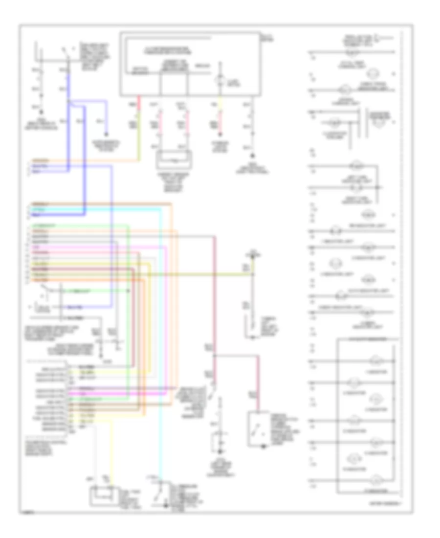
Instrument Cluster Wiring Diagram, Luxury & Performance (1 of 2) for Isuzu Trooper Limited 2000

List of elements for Instrument Cluster Wiring Diagram, Luxury & Performance (1 of 2) for Isuzu Trooper Limited 2000:
- (right kick panel)
- A/t shift indicator control unit (behind dash, left of steering column)
- Abs indicator light
- Alarm & relay control unit (above right kick panel)
- Alternator (on lower right front of engine)
- Anti-lock brakes system
- Automatic transmission mode switch (left side of transmission)
- B-49
- B-6
- Battery
- Brake warning light
- C-3 turn back fuse 15a
- C10 meter gauge fuse 10a
- C11 (audio [acc]) mirror) fuse 10a
- C15 (audio [b]) fuse 20a
- Charge warning light
- Cruise control system
- Cruise main indicator light
- Cruise set indicator light
- Dash fuse box (behind left kick panel)
- Dim input
- Dr seat belt unbuckled input
- Engine coolant temperature gauge
- Exterior lights system
- Fuel gauge
- G104 (left rear corner of engine compartment)
- G203 (above right dash side trim panel)
- Gnd
- Ground
- Headlights system
- Hot at all times
- Hot in acc or on
- Hot in on or start
- I-10
- I-9
- Ign
- Ignition
- Indicator ctrl
- Interior lights system
- Low fuel indicator light
- Malfunction indicator light (check engine light)
- Meter assembly
- Note: do not check resistance of solid state modules in meter assembly
- Oil pressure indicator light
- P-8
- Pnk
- Position input
- Power drive indicator light
- Red
- Rpm in
- Seat belt indicator light
- Speedometer (solid state)
- Tachometer (solid state)
- To a/t oil temp warning light (diagram 2 of 2)
- Torque on demand (tod) control unit (beneath front passenger's seat)
- Trans- missions system
- Vss input
- Winter drive indicator light
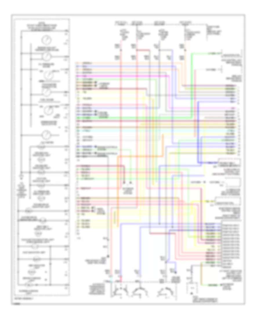
Instrument Cluster Wiring Diagram, Luxury & Performance (2 of 2) for Isuzu Trooper Limited 2000
List of elements for Instrument Cluster Wiring Diagram, Luxury & Performance (2 of 2) for Isuzu Trooper Limited 2000:
- (right rear corner of engine compartment on inner fender panel)
- 1 indicator
- 1 indicator light
- 2 indicator
- 2 indicator light
- 3 indicator
- 3 indicator light
- A/c system
- A/t oil temp warning light
- A/t shift indicator
- Air bag warning light
- Altimeter/barometer, thermometer & compass
- Ambient air temperature input/output
- Ambient sensor (on top left front of radiator bracket)
- Auto indicator light
- Brake fluid level switch (closed w/low brake fluid level) (on brake fluid reservoir)
- Check indicator light
- Check trans indicator light
- D indicator
- Driver's seat belt switch (open w/seat belt buckled) (in driver's seat belt buckle)
- E21
- E22
- From low fuel indicator light (diagram 1 of 2)
- Fuel gauge ctrl
- Fuel tank unit (on right front of fuel tank)
- G104 (left rear corner of engine compartment)
- G105
- G203 (above right dash trim panel)
- G302 (beow rear of center console)
- Ground
- Hi beam indicator light
- I-10
- I-9
- Ignition on input
- Illumi- nation
- Illumination (6 bulbs)
- Indicator ctrl
- Interior lights system
- Left turn indicator light
- Meter assembly
- Multi- meter
- N indicator
- Odometer trip meter
- Oil pressure switch (closed w/low oil pressure) (lower front of engine, at oil filter)
- P indicator
- Powertrain control module (pcm) (right side of engine compt)
- R indicator
- Red
- Right turn indicator light
- Rpm output
- Rr indicator light
- Sensor gnd
- Solid state
- Thermo unit (on left front of engine)
- Vehicle speed sensor (vss) (on underside of vehicle, right rear of front transfer case)
- Vss input
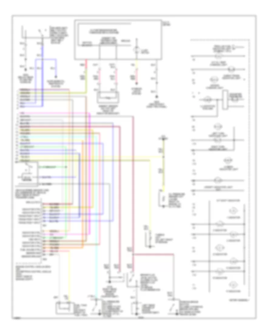
Instrument Cluster Wiring Diagram, S Model (1 of 2) for Isuzu Trooper Limited 2000
List of elements for Instrument Cluster Wiring Diagram, S Model (1 of 2) for Isuzu Trooper Limited 2000:
- 4wd control unit (behind front console)
- 4wd indicator light
- A/t shift indicator control unit (behind dash, left of steering column)
- Abs indicator light
- Alarm & relay control unit (above right kick panel)
- Alternator (on lower right front of engine)
- Automatic transmission mode switch (left side of transmission)
- B-6
- Battery
- Brake warning light
- C-3 turn back fuse 15a
- C-4
- C10 meter gauge fuse 10a
- C11 (audio [acc]) mirror) fuse 10a
- C15 (audio (b)) fuse 20a
- Charge warning light
- Cruise control system
- Cruise main indicator light
- Cruise set indicator light
- Dash fuse box (behind left kick panel)
- Dim input
- Dr seat belt unbuckled input
- Electronic brake control module (ebcm) (right front of engine compartment)
- Engine controls system
- Engine coolant temperature gauge
- Exterior lights system
- Fuel gauge
- G104 (left rear corner of engine compartment)
- G203 (above right dash side trim panel)
- Gnd
- Ground
- Head- lights system
- Hot at all times
- Hot in acc or on
- Hot in on or start
- I-10
- I-9
- Ign
- Ignition
- Indicator ctrl
- Interior lights system
- Low fuel indicator light
- Malfunction indicator light (check engine light)
- Meter assembly
- Note: do not check resistance of solid state modules in meter assembly
- Oil pressure gauge
- Oil pressure indicator light
- P-8
- Pnk
- Position input
- Power drive indicator light
- Rpm in
- Seat belt indicator light
- Speedometer (solid state)
- Srs unit (behind front console)
- Tachometer (solid state)
- To a/t oil temp warning light (diagram 2 of 2)
- Voltmeter
- Vss input
- Winter drive indicator light
Instrument Cluster Wiring Diagram, S Model (2 of 2) for Isuzu Trooper Limited 2000
List of elements for Instrument Cluster Wiring Diagram, S Model (2 of 2) for Isuzu Trooper Limited 2000:
- (left rear corner of engine compartment)
- 1 indicator
- 2 indicator
- 3 indicator
- A/c system
- A/t oil temp warning light
- A/t shift indicator
- Air bag warning light
- Altimeter/barometer, thermometer & compass
- Ambient air temperature input/output
- Ambient sensor (on top left front of radiator bracket)
- Brake fluid level switch (closed w/low brake fluid level) (on brake fluid reservoir)
- Check trans indicator light
- D indicator
- Driver's seat belt switch (open w/seat belt buckled) (in driver's seat belt buckle)
- E21
- E22
- Engine control module (ecm) (or) powertrain control module (pcm) (right side of engine compt)
- From low fuel indicator light (diagram 1 of 2)
- Fuel gauge ctrl
- Fuel tank unit (on right front of fuel tank)
- G104
- G105 (right rear corner of engine compartment)
- G203 (above right dash trim panel)
- G302 (below rear of center console)
- Ground
- Hi beam indicator light
- I-10
- I-9
- Ignition on input
- Illumi- nation
- Illumination (6 bulbs)
- Indicator ctrl
- Interior lights system
- Left turn indicator light
- Meter assembly
- Multi- meter
- N indicator
- Odometer trip meter
- Oil pressure sender unit (lower front of engine, at oil filter)
- Oil pressure switch (closed w/low oil pressure) (lower front of engine, at oil filter)
- P indicator
- R indicator
- Red
- Right turn indicator light
- Rpm output
- Sensor gnd
- Sensor ground
- Solid state
- Thermo unit (on left front of engine)
- Trans posit input
- Upshift indicator light (m/t)
- Vehicle speed sensor (vss) (on underside of vehicle, right rear of front transfer case)
- Vss input