INSTRUMENT CLUSTER
Instrument Cluster Wiring Diagram for Mazda B3000 Dual Sport 2005
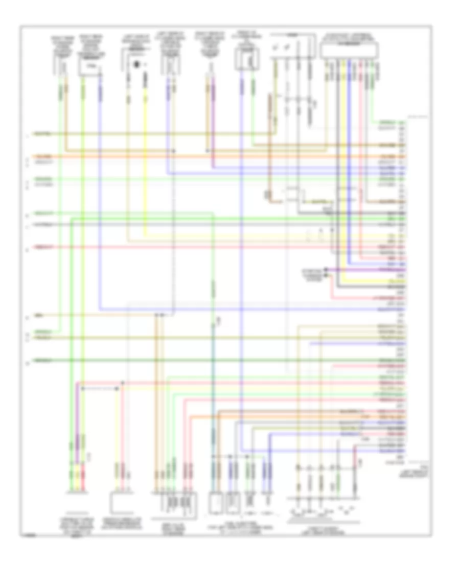
List of elements for Instrument Cluster Wiring Diagram for Mazda B3000 Dual Sport 2005:
- (front of cylinder head) oil control valve
- (in exhaust, upstream of catalytic converter) a/f sensor
- (left rear of cylinder head) variable intake air solenoid valve
- (left side of engine block) knock sensor
- (right rear of cylinder head) variable tumble solenoid valve
- (right rear of engine) engine coolant temperature sensor
- (right rear of engine) purge solenoid valve
- 0140-101b
- 0140-107a
- 0140-107b
- 2aa
- 2ab
- 2ac
- 2ad
- 2ae
- 2af
- 2ag
- 2ah
- 2ai
- 2aj
- 2ak
- 2al
- 2am
- 2an
- 2ao
- 2ap
- 2aq
- 2ar
- 2as
- 2at
- 2au
- 2av
- 2aw
- 2ax
- 2ay
- 2az
- 2ba
- 2bb
- 2bc
- 2bd
- 2be
- 2bf
- 2bg
- 2bh
- C-02
- C-14
- C-69
- Egr valve (right rear of engine)
- Fuel injectors (top left side of cylinder head, at 1, 2, 3, 4 cylinder)
- Ho2s
- Manifold absolute pressure sensor (on intake manifold)
- Nca
- Pcm (left rear of engine compt)
- Red
- Starting/ charging system
- Throttle body (left rear of engine)
- Variable tumble shutter valve position sensor (on throttle body)
 English