INSTRUMENT CLUSTER
Collision Avoidance Wiring Diagram for Mercedes-Benz ML350 BlueTEC 2013

List of elements for Collision Avoidance Wiring Diagram for Mercedes-Benz ML350 BlueTEC 2013:
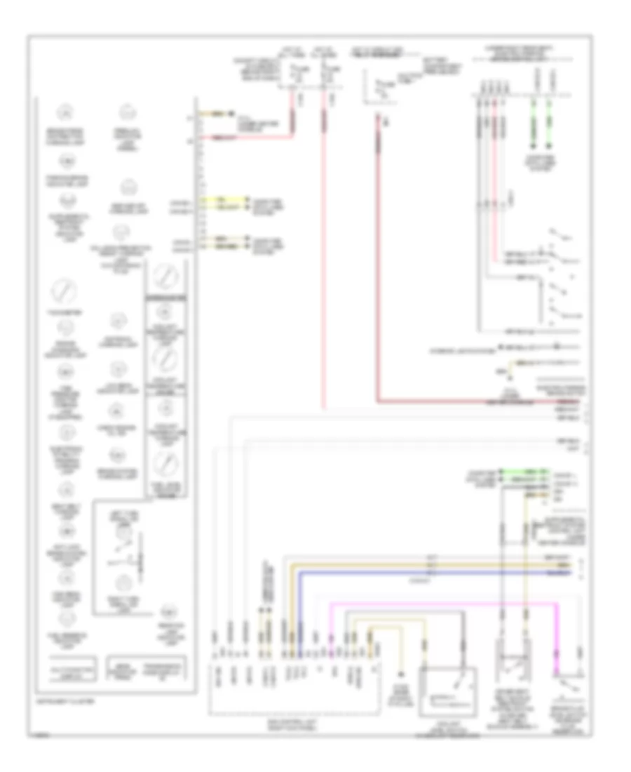
Instrument Cluster Wiring Diagram (1 of 2) for Mercedes-Benz ML350 BlueTEC 2013
List of elements for Instrument Cluster Wiring Diagram (1 of 2) for Mercedes-Benz ML350 BlueTEC 2013:
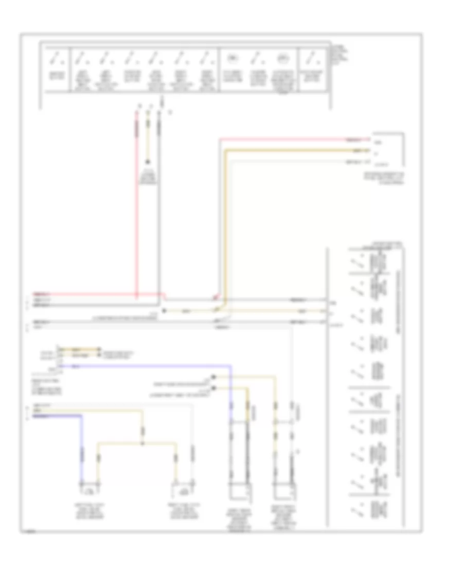
Instrument Cluster Wiring Diagram (2 of 2) for Mercedes-Benz ML350 BlueTEC 2013
List of elements for Instrument Cluster Wiring Diagram (2 of 2) for Mercedes-Benz ML350 BlueTEC 2013:
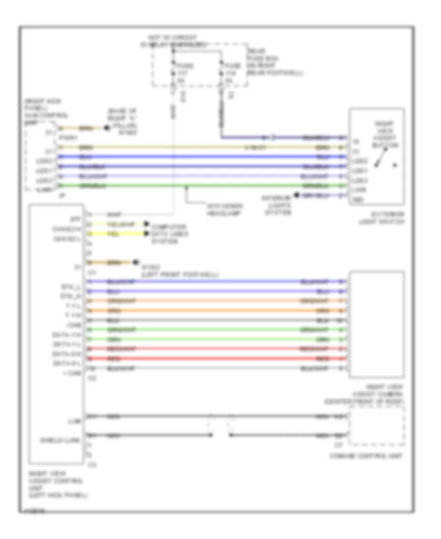
Night Vision Wiring Diagram for Mercedes-Benz ML350 BlueTEC 2013
List of elements for Night Vision Wiring Diagram for Mercedes-Benz ML350 BlueTEC 2013:
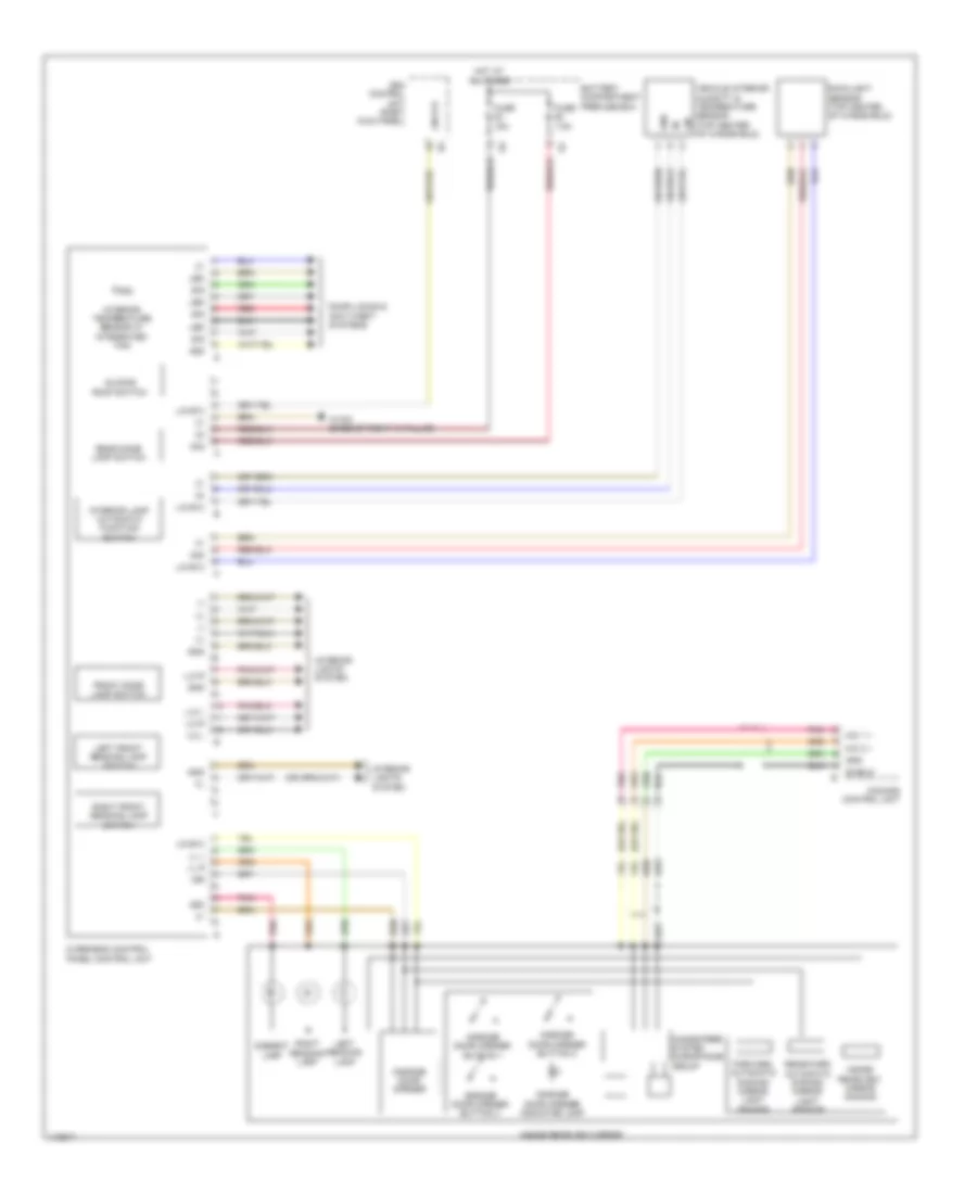
Overhead Console Wiring Diagram for Mercedes-Benz ML350 BlueTEC 2013
List of elements for Overhead Console Wiring Diagram for Mercedes-Benz ML350 BlueTEC 2013:
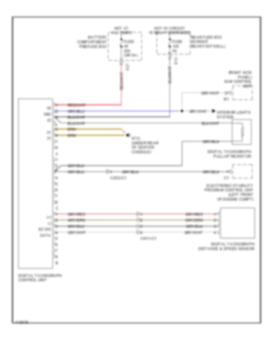
Tachograph Wiring Diagram for Mercedes-Benz ML350 BlueTEC 2013
List of elements for Tachograph Wiring Diagram for Mercedes-Benz ML350 BlueTEC 2013: