INSTRUMENT CLUSTER
Instrument Cluster Wiring Diagram for Mercedes-Benz ML430 2001

List of elements for Instrument Cluster Wiring Diagram for Mercedes-Benz ML430 2001:
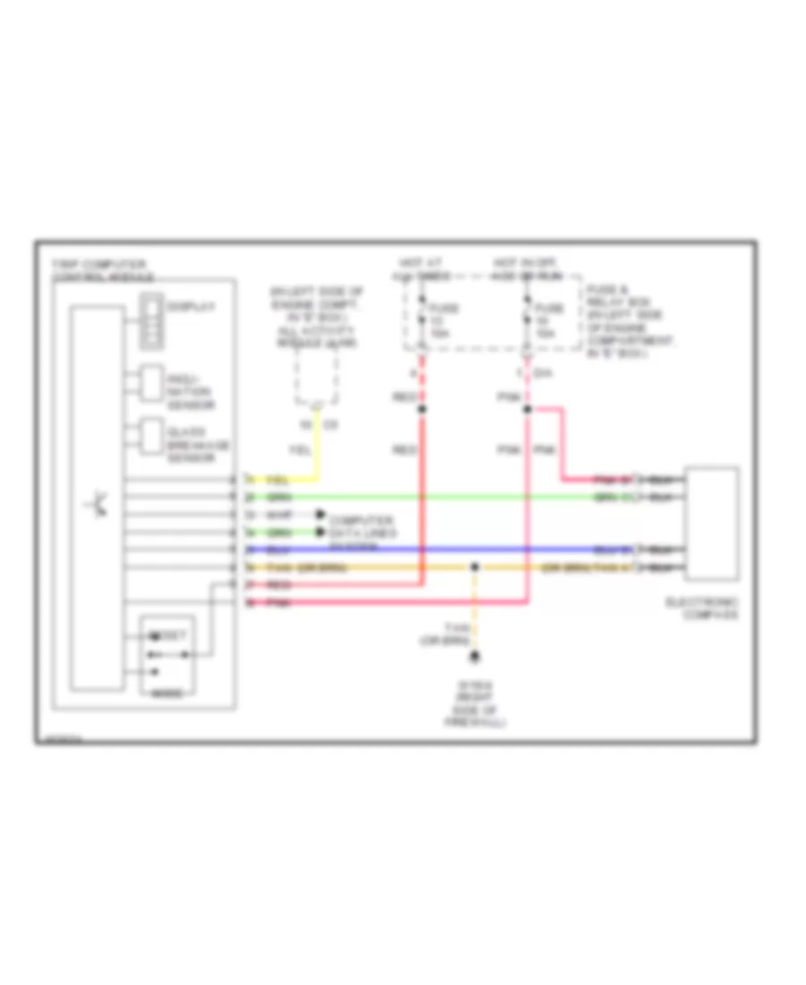
Trip Computer Wiring Diagram for Mercedes-Benz ML430 2001
List of elements for Trip Computer Wiring Diagram for Mercedes-Benz ML430 2001: