INSTRUMENT CLUSTER
Instrument Cluster Wiring Diagram for Mercedes-Benz ML500 2005

List of elements for Instrument Cluster Wiring Diagram for Mercedes-Benz ML500 2005:
- (behind right kick panel)
- (behind right kick panel) w29/2
- (in left side of engine compartment) fuse & relay box
- 15c
- A10
- A11
- A12
- A13
- A14
- A15
- A16
- A17
- A18
- Abs mil
- Airbag off indicator lamp
- All activity module (aam) (in left side of engine compt, in "e" box)
- Ambient temperature sensor (behind left side of front grille)
- B10
- B11
- B12
- Bas/esp mil
- Battery
- Brake pad wear indicator lamp
- C/c
- C/d
- Check engine mil
- Computer data lines system
- Data link connector (partial) (below left side of dash)
- Digital clock set switch
- Ect gauge
- Electronic clock
- Electronic ecl switch (in left rear of engine compartment)
- Electronic speedo- meter
- Ets mil
- Ets warning lamp
- Exterior lights system
- Fog lamp indicator lamp
- Fuel level gauge
- Fuel level sensor
- Fuel pump (on top of fuel tank)
- Fuel reserve ind
- Fuse & relay box (in left side of engine compartment, in "e" box)
- Fuse 15a
- Fuse 7.5a
- Generator charge indicator lamp
- Headlights system
- High beam indicator lamp
- Hot in off, acc or run
- Hot in run or start
- Instrument cluster
- Instrument illumination (3 bulbs)
- Instrument illumination rheostat
- Interior lights system
- Left turn signal indicator lamp
- Limit mil
- Low brake fluid level/ parking brake/ brake-force proportioning indicator lamp
- Low ecl indicator lamp
- Low engine oil level indicator lamp
- Low range indicator lamp
- Low washer fluid level indicator lamp
- Ml/a
- Outside temp ind
- Pnk
- Red
- Restraint system control module (below center console)
- Right front footwell fuse & relay box (below right side of dash, behind kick panel)
- Right turn signal indicator lamp
- Seat belt reminder lamp
- Srs mil
- Starter key switch (closed w/key in starter switch)
- Starter switch
- Starting/charging system
- Steering lock switch
- Steering lock warning lamp
- Tacho- meter
- Trip odometer reset button
- W29/2
- Warning buzzer
- Windshield washer fluid level switch (in fluid reservoir)
- X12/12
- X12/9
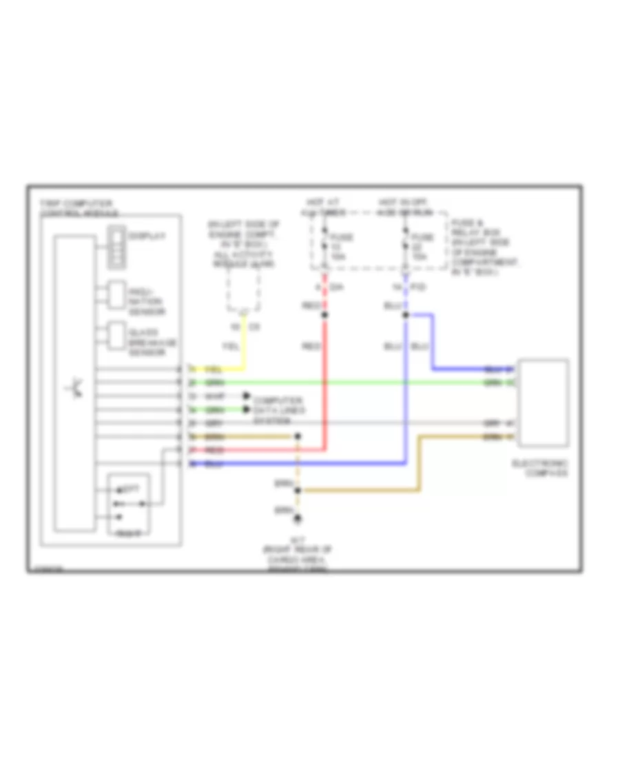
Trip Computer Wiring Diagram for Mercedes-Benz ML500 2005
List of elements for Trip Computer Wiring Diagram for Mercedes-Benz ML500 2005:
- (in left side of engine compt, in "e" box) all activity module (aam)
- Computer data lines system
- D/a
- Display
- Electronic compass
- Fuse & relay box (in left side of engine compartment, in "e" box)
- Fuse 10a
- Fuse 15a
- Glass breakage sensor
- Hot at all times
- Hot in off, acc or run
- Incli- nation sensor
- Left
- P/d
- Red
- Right
- Trip computer control module
- W7 (right rear of cargo area, behind trim)