INSTRUMENT CLUSTER
Instrument Cluster Wiring Diagram (1 of 2) for Mitsubishi Lancer ES 2002

List of elements for Instrument Cluster Wiring Diagram (1 of 2) for Mitsubishi Lancer ES 2002:
- (behind left side of dash) g7
- A/t
- Abs ind
- Anti-lock brakes system
- Brake fluid level switch (on brake master cylinder reservoir)
- Brake ind
- C01
- C02
- C210
- C214
- Charge ind
- Combination meter
- Control circuit
- Cruise control system
- Cruise ind
- Door ind
- Engine coolant temperature gauge unit (on rear of engine)
- Exterior lights system
- Exterior lights system
- Fuel gauge
- Fuel ind
- G14 (behind left side of dash)
- G7 (behind left side of dash)
- Hot in on or start
- Illumination
- Interior lights system
- Joint connector 5 (behind instru- ment cluster)
- Junction block (behind left side of dash)
- Left turn ind
- M/t
- Malfunction ind light
- Multi-
- Nca
- Odometer/trip
- Oil ind
- Oil pressure switch (on right front of engine)
- Parking brake switch (at base of parking brake lever)
- Pnk
- Purpose fuse 2 7.5
- Purpose fuse 3 7.5a
- Red
- Right turn ind
- Seat belt ind
- Speedometer
- Srs ind
- Starting/charging system
- Tachometer
- Temperature gauge
- Warning systems
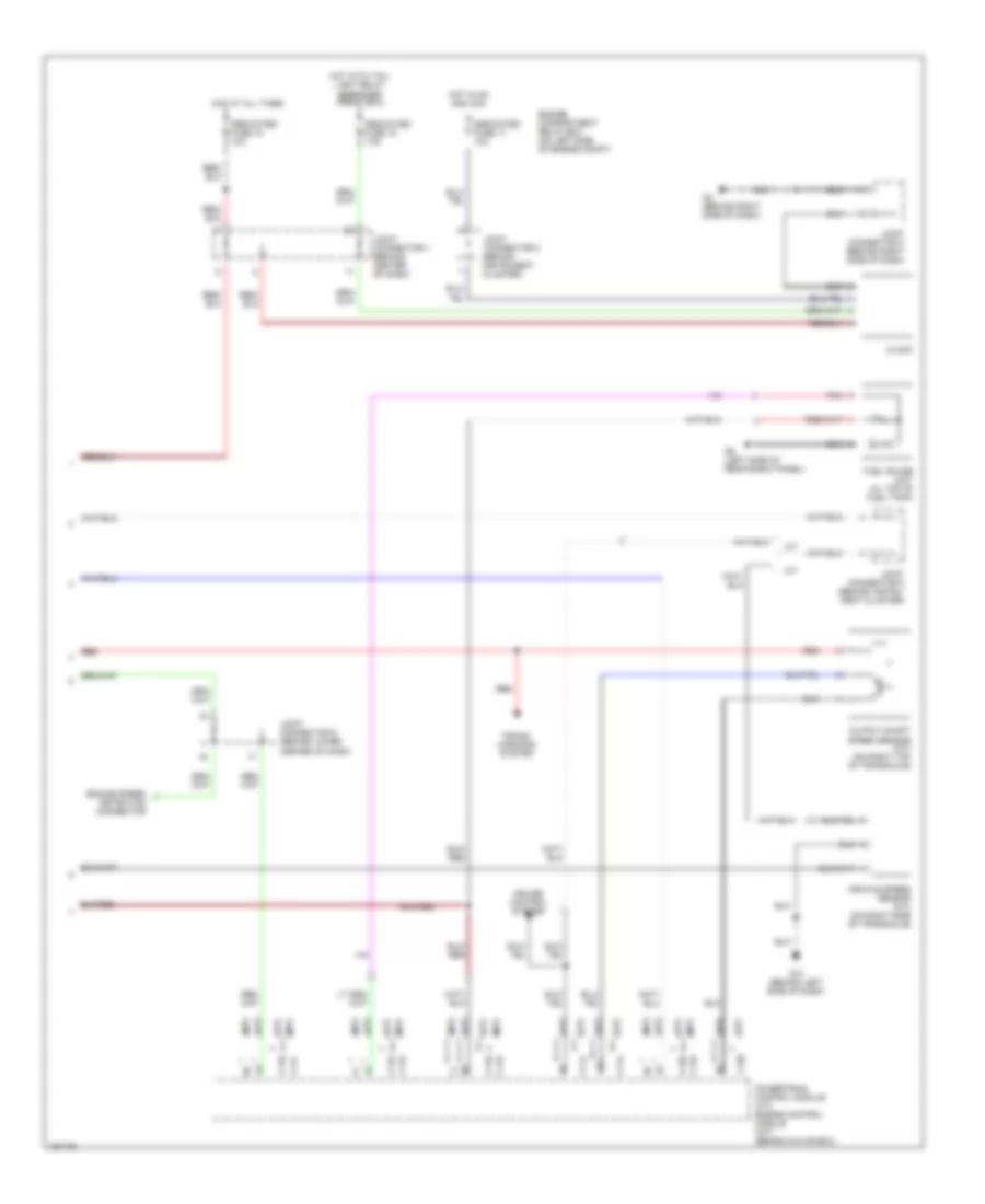
Instrument Cluster Wiring Diagram (2 of 2) for Mitsubishi Lancer ES 2002
List of elements for Instrument Cluster Wiring Diagram (2 of 2) for Mitsubishi Lancer ES 2002:
- (a/t)
- (m/t)
- A/t
- C114
- C115
- C117
- C118
- C119
- C120
- Clock
- Cruise control system
- Dedicated fuse 15 7.5a
- Dedicated fuse 17 10a
- Dedicated fuse 18 10a
- Detection connector
- Engine compartment relay box (on left side of engine compt)
- Engine speed
- Fuel gauge unit (in top of fuel tank)
- G14 (behind left side of dash)
- G3 (behind right side of dash)
- G9 (left side of rear shelf panel)
- Hot at all times
- Hot in on and acc
- Hot with tail- light relay energized (front ecu)
- Joint connector 1 (behind center of dash)
- Joint connector 2 (behind instrument cluster)
- Joint connector 3 (behind right side of dash)
- Joint connector 5 (behind instru- ment cluster)
- Joint connector 6 (behind lower center of dash)
- M/t
- Output shaft speed sensor (a/t) (on right top of transaxle)
- Pnk
- Powertrain control module (a/t) engine control module (m/t) (behind glove box)
- Red
- Trans- missions system
- Vehicle speed sensor (m/t) (on right side of transaxle)