INSTRUMENT CLUSTER
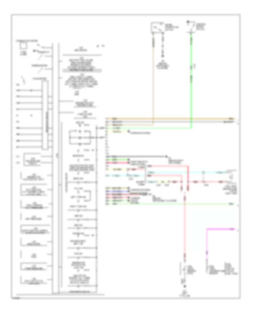
Instrument Cluster Wiring Diagram, Evolution (1 of 2) for Mitsubishi Lancer ES 2014

List of elements for Instrument Cluster Wiring Diagram, Evolution (1 of 2) for Mitsubishi Lancer ES 2014:
- Abs ind
- Beam ind
- Brake ind
- C-23
- Can transceiver circuit
- Combination meter
- Computer data lines system
- Cpu
- Cruise ind
- Driver's seat belt ind
- Fog ind
- Fuel level sensor (main)
- Fuel level sensor (sub) (top of fuel tank)
- Fuel pump module (top of fuel tank)
- Fuel tank temperature sensor
- G22 (right side of front of center console)
- G4 (behind right kick panel)
- G6 (behind center of dash)
- Generator malfunction light ind
- Illum
- Interface circuit
- Interior lights system
- Lcd (abs, asc off, asc operation, tarmac, brake, gravel, snow, acd, ayc, asc warning)
- Lcd (each door)
- Lcd (engine coolant temperature)
- Lcd (fuel warning, oil)
- Lcd (generator malfunction light)
- Lcd (key reminder)
- Lcd (kos)
- Lcd (odo/trip, fuel gauge, temperature gauge, service reminder, outside temperature)
- Lcd (seat belt)
- Lcd (shift position, normal, sport, s-sport)
- Lcd (srs)
- Lcd (theft alarm indicator)
- Lcd (tire pressure)
- Lcd brake, fuel warning, oil
- Led drive circuit
- Left turn ind
- Malfunction ind light (service engine soon or check engine lamp)
- Meter information switch
- Parking brake switch
- Pnk
- Red
- Rheostat
- Right turn ind
- Sound systems
- Speedometer
- Srs ind
- Tachometer
- Tail ind
- Tone alarm
- Warning systems
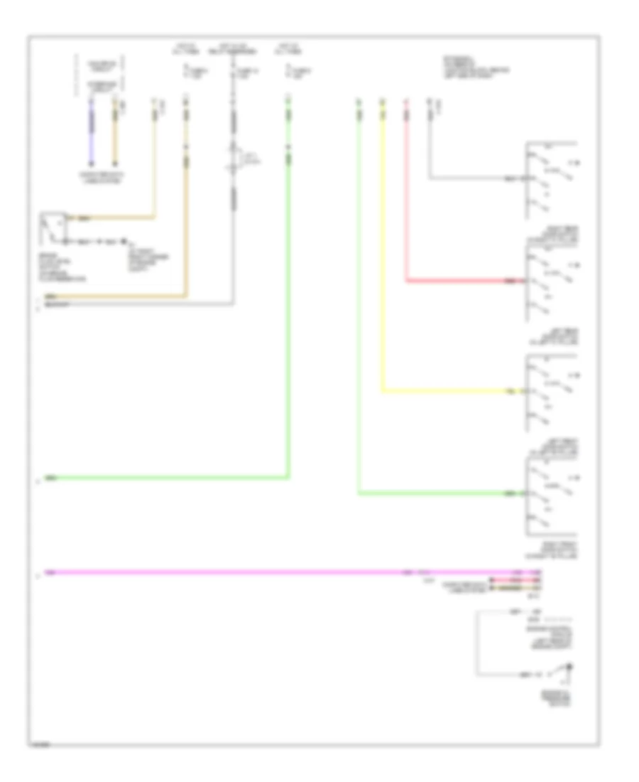
Instrument Cluster Wiring Diagram, Evolution (2 of 2) for Mitsubishi Lancer ES 2014
List of elements for Instrument Cluster Wiring Diagram, Evolution (2 of 2) for Mitsubishi Lancer ES 2014:
- B-09
- B-10
- Brake fluid level switch (on brake fluid reservoir)
- C-301
- C-312
- C-313
- C-47
- Can drive circuit
- Computer data lines system
- Engine control module (left rear of engine compt)
- Engine oil pressure switch
- Etacs-ecu (on rear of junction block, behind left end of dash)
- Fuse 12 7.5a
- Fuse 8 7.5a
- Fuse 9 15a
- G1 (at right front corner of engine compt)
- Hot at all times
- Hot w/ ig1 relay energized
- Interface circuit
- J/c 1 (c-101)
- Left front door switch (in left "b" pillar)
- Left rear door switch (in left "c" pillar)
- Pnk
- Red
- Right front door switch (in right "b" pillar)
- Right rear door switch (in right "c" pillar)
Instrument Cluster Wiring Diagram, Except Evolution (1 of 2) for Mitsubishi Lancer ES 2014
List of elements for Instrument Cluster Wiring Diagram, Except Evolution (1 of 2) for Mitsubishi Lancer ES 2014:
- Abs ind
- Asc ind
- Asc off ind (except 2.0l turbo w/o color liquid crystal display)
- Beam ind
- Brake ind
- C-22
- Can transceiver circuit
- Combination meter
- Computer data lines system
- Cpu
- Cruise ind
- D-08
- Driver's seat belt ind
- Fog ind
- Fuel level sensor (main)
- Fuel level sensor (sub) (top of fuel tank)
- Fuel pump module (top of fuel tank)
- Fuel tank temperature sensor
- G11 (left "c" pillar)
- G4 (behind right kick panel)
- G5 (behind instrument cluster)
- Generator malfunction light ind
- Illum
- Interface circuit
- Interior lights system
- Lcd (abs, acd(2.0l turbo), asc off, asc operation, asc warning, brake, gravel (2.0l turbo), snow (2.0l turbo, & tarmac (2.0l turbo)
- Lcd (cvt position, cvt temperature & cvt failure)
- Lcd (each door)
- Lcd (engine coolant temperature)
- Lcd (fuel warning & oil pressure)
- Lcd (generator malfunction light)
- Lcd (key reminder)
- Lcd (kos)
- Lcd (odo/trip, fuel gauge, service reminder, information frost, outside temperature & temperature gauge)
- Lcd (shift position, normal sport & s-sport)
- Lcd (theft-alarm ind)
- Lcd (tire pressure)
- Lcd 2wd, 4wd auto & 4wd lock
- Lcd abs, brake
- Lcd srs
- Led drive circuit
- Left turn ind
- Malfunction ind light (service engine soon or check engine lamp)
- Meter information switch
- Parking brake switch
- Pnk
- Red
- Rheostat
- Right turn ind
- Sound systems
- Speedometer
- Srs ind
- Tachometer
- Tail ind
- Tire pressure ind
- Tone alarm
- Turbo
- Warning systems
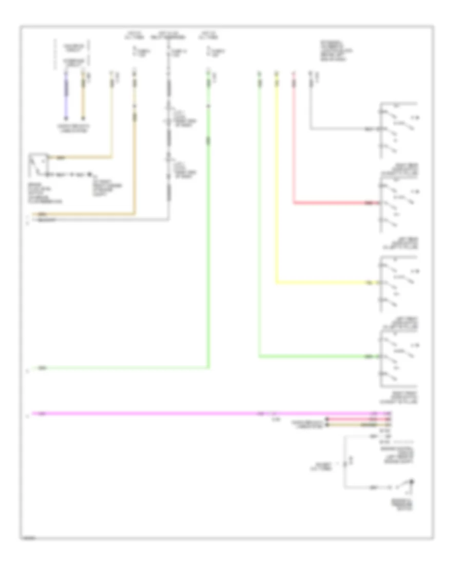
Instrument Cluster Wiring Diagram, Except Evolution (2 of 2) for Mitsubishi Lancer ES 2014
List of elements for Instrument Cluster Wiring Diagram, Except Evolution (2 of 2) for Mitsubishi Lancer ES 2014:
- B-108
- B-109
- B-16
- Brake fluid level switch (on brake fluid reservoir)
- C-301
- C-312
- C-313
- C-317
- C-39
- Can drive circuit
- Computer data lines system
- Engine control module (left rear of engine compt)
- Engine oil pressure switch
- Etacs-ecu (on rear of junction block, behind left end of dash)
- Except 2.0l turbo
- Fuse 12 7.5a
- Fuse 8 7.5a
- Fuse 9 15a
- G1 (at right front corner of engine compt)
- Hot at all times
- Hot w/ ig1 relay energized
- Interface circuit
- J/c 1 (c-03) (right end of dash)
- Left front door switch (in left "b" pillar)
- Left rear door switch (in left "c" pillar)
- Pnk
- Red
- Right front door switch (in right "b" pillar)
- Right rear door switch (in right "c" pillar)