INSTRUMENT CLUSTER
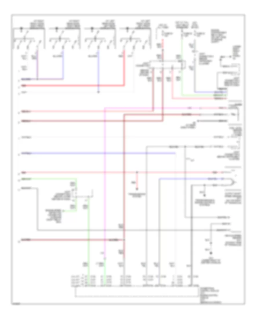
Instrument Cluster Wiring Diagram, Evolution (1 of 2) for Mitsubishi Lancer O-Z Rally 2005

List of elements for Instrument Cluster Wiring Diagram, Evolution (1 of 2) for Mitsubishi Lancer O-Z Rally 2005:
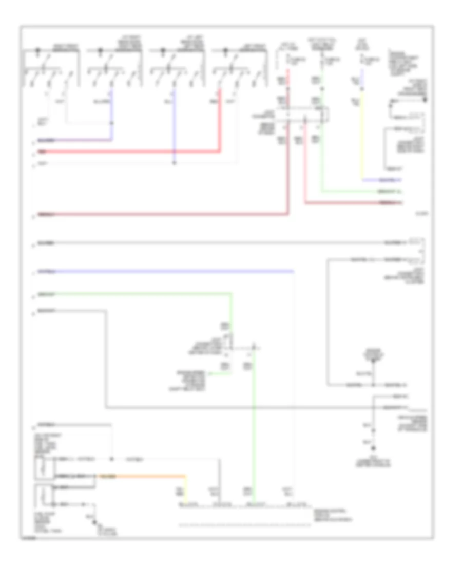
Instrument Cluster Wiring Diagram, Evolution (2 of 2) for Mitsubishi Lancer O-Z Rally 2005
List of elements for Instrument Cluster Wiring Diagram, Evolution (2 of 2) for Mitsubishi Lancer O-Z Rally 2005:
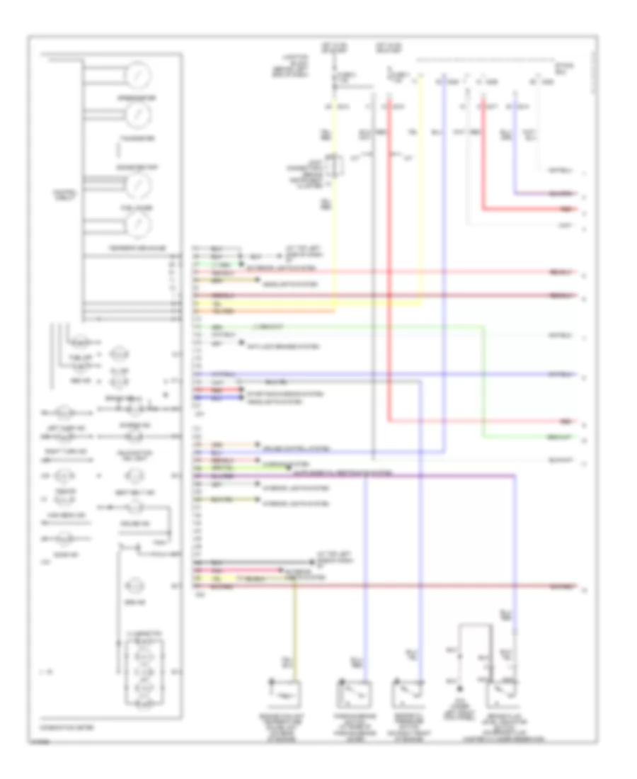
Instrument Cluster Wiring Diagram, Except Evolution (1 of 2) for Mitsubishi Lancer O-Z Rally 2005
List of elements for Instrument Cluster Wiring Diagram, Except Evolution (1 of 2) for Mitsubishi Lancer O-Z Rally 2005:
Instrument Cluster Wiring Diagram, Except Evolution (2 of 2) for Mitsubishi Lancer O-Z Rally 2005
List of elements for Instrument Cluster Wiring Diagram, Except Evolution (2 of 2) for Mitsubishi Lancer O-Z Rally 2005: