INSTRUMENT CLUSTER
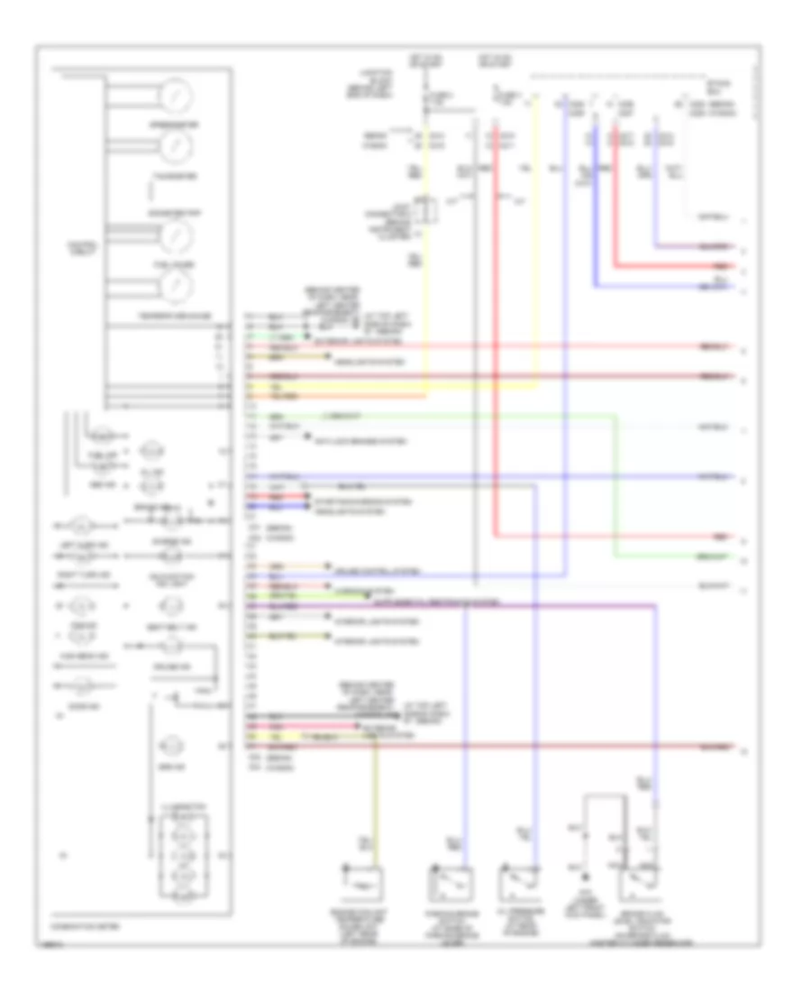
Instrument Cluster Wiring Diagram, Evolution (1 of 2) for Mitsubishi Lancer Sportback Ralliart 2004

List of elements for Instrument Cluster Wiring Diagram, Evolution (1 of 2) for Mitsubishi Lancer Sportback Ralliart 2004:
- (at top left side of dash) g7
- Abs ind
- Anti-lock brakes system
- Anti-theft system
- Brake fluid level indicator switch (on brake fluid master cylinder reservoir)
- Brake ind
- C01
- C02
- C210
- C214
- C217
- C226
- C228
- Charge ind
- Combination meter
- Control circuit
- Door ind
- Engine controls system
- Engine coolant temperature gauge unit (left rear of engine)
- Etacs ecu
- Exterior lights system
- Fog ind
- Fuel gauge
- Fuel ind
- Fuse 2 7.5a
- G14 (under front of center console)
- Headlights system
- High beam ind
- Hot in on or start
- Illumination
- Interior lights system
- Joint connector 4
- Junction block (behind left end of dash)
- Left turn ind
- Malfunction ind light
- Nca
- Odometer/trip
- Oil ind
- Oil pressure switch (at rear of engine)
- Parking brake switch (at base of parking brake lever)
- Pnk
- Red
- Right turn ind
- Seat belt ind
- Security ind
- Speedometer
- Srs ind
- Starting/charging system
- Tachometer
- Temperature gauge
- Warning system
- Water spray ind
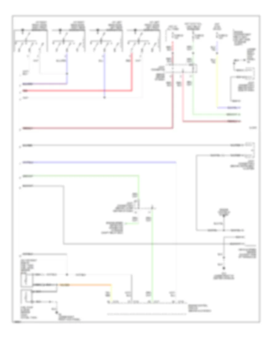
Instrument Cluster Wiring Diagram, Evolution (2 of 2) for Mitsubishi Lancer Sportback Ralliart 2004
List of elements for Instrument Cluster Wiring Diagram, Evolution (2 of 2) for Mitsubishi Lancer Sportback Ralliart 2004:
- (at left front door) left front door switch
- (at left rear door) left rear door switch
- (at right front door) right front door switch
- (at right rear door) right rear door switch
- (on top right side of fuel tank) fuel level sensor (sub)
- (under right front kick panel) g3
- C115
- C117
- C119
- Clock
- Detection connector (in engine compt relay box)
- Engine compartment relay box (on left side of engine compt)
- Engine control module (behind glove box)
- Engine controls system
- Engine speed
- Fuel pump & level sensor (main) (in fuel tank)
- Fuse 20 7.5a
- Fuse 22 10a
- Fuse 23 10a
- G14 (under front of center console)
- G2 (under right front kick panel)
- Hot at all times
- Hot in on or acc
- Hot with tail- light relay energized
- Joint connector (behind center of dash)
- Joint connector 3 (behind right side of dash)
- Joint connector 5 (behind instrument cluster)
- Joint connector 6 (behind lower center of dash)
- Nca
- Red
- Vehicle speed sensor (on right side of transaxle)
Instrument Cluster Wiring Diagram, Except Evolution (1 of 2) for Mitsubishi Lancer Sportback Ralliart 2004
List of elements for Instrument Cluster Wiring Diagram, Except Evolution (1 of 2) for Mitsubishi Lancer Sportback Ralliart 2004:
- (at top left side of dash) g7
- (behind center of dash, near left center reinforcement) (at top left g6 side of dash) g7
- (behind center of dash, near left center reinforcement) g6
- (sedan)
- (wagon)
- A/t
- Abs ind
- Anti-lock brakes system
- Brake fluid level indicator switch (on brake fluid master cylinder reservoir)
- Brake ind
- C01
- C02
- C04
- C210
- C211
- C214
- C214 c215
- C215
- C217 c218
- C226
- C227
- C228
- C228 (sedan)
- C229
- C229 (wagon)
- Charge ind
- Combination meter
- Control circuit
- Cruise control system
- Cruise ind
- Door ind
- Engine coolant temperature gauge unit (left rear of engine)
- Etacs ecu
- Exterior lights system
- Exterior lights system
- Fog ind
- Fuel gauge
- Fuel ind
- Fuse 2 7.5a
- Fuse 3 7.5a
- G15 (under left front kick panel)
- Headlights system
- High beam ind
- Hot in on or start
- Illumination
- Interior lights system
- Joint connector 5 (behind instrument cluster)
- Junction block (behind left end of dash)
- Left turn ind
- M/t
- Malfunction ind light
- Nca
- Odometer/trip
- Oil ind
- Oil pressure switch (at rear of engine)
- Parking brake switch (at base of parking brake lever)
- Pnk
- Red
- Right turn ind
- Seat belt ind
- Sedan
- Speedometer
- Srs ind
- Starting/charging system
- Tachometer
- Temperature gauge
- Wagon
- Warning system
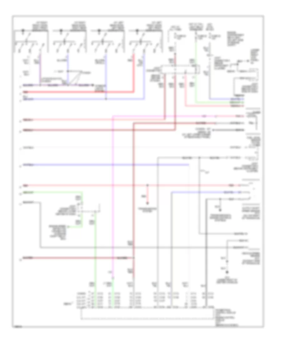
Instrument Cluster Wiring Diagram, Except Evolution (2 of 2) for Mitsubishi Lancer Sportback Ralliart 2004
List of elements for Instrument Cluster Wiring Diagram, Except Evolution (2 of 2) for Mitsubishi Lancer Sportback Ralliart 2004:
- (at left front door) left front door switch
- (at left rear door) left rear door switch
- (at right front door) right front door switch
- (at right rear door) right rear door switch
- (sedan)
- (under right front kick panel) g3
- (wagon)
- 2.0l a/t
- 2.0l m/t
- 2.4l a/t
- 2.4l m/t
- C112
- C114
- C115
- C116
- C117
- C118
- C119
- C120
- C133
- C134
- C137
- C138
- Clock
- Detection connector (in engine compt relay box)
- Engine compartment relay box (on left side of engine compt)
- Engine speed
- Fuel level sensor (in fuel tank)
- Fuse 20 7.5a
- Fuse 22 10a
- Fuse 23 10a
- G14 (under front of center console)
- G17
- G9 (at left upper corner of rear shelf panel)
- Hot at all times
- Hot in on or acc
- Hot w/ tail- light relay energized
- Interior lights system
- Joint connector (behind center of dash)
- Joint connector 2 (behind instrument cluster)
- Joint connector 3 (behind right side of dash)
- Joint connector 5 (behind instrument cluster)
- Joint connector 6 (behind lower center of dash)
- Liftgate switch (wagon)
- M/t
- Output shaft speed sensor (a/t) (on top right of transaxle)
- Pnk
- Powertrain control module (a/t) engine control module (m/t) (behind glove box)
- Red
- Sedan
- Transmissions & engine controls systems
- Transmissions system
- Vehicle speed sensor (m/t) (on right side of transaxle)
- Wagon