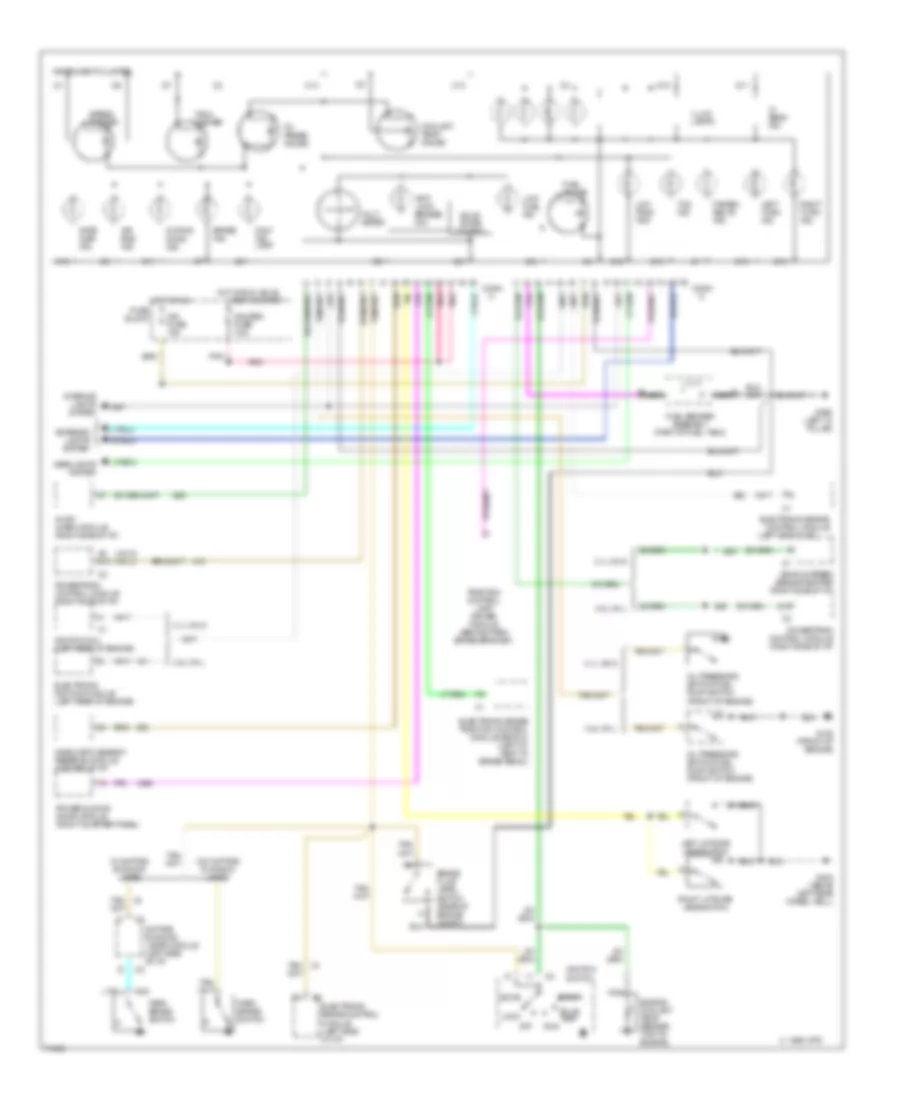
INSTRUMENT CLUSTER
Instrument Cluster Wiring Diagram for Oldsmobile Silhouette 1995
List of elements for Instrument Cluster Wiring Diagram for Oldsmobile Silhouette 1995:
- (left side of i/p)
- (vin d) (vin l)
- 1995 vftc c
- 3.1l vin d
- 3.8l vin l
- A5 d13
- Accy
- Air bag ind.
- Anti- lock brakes ind.
- Audio alarm module (right side of i/p)
- Brake fluid level switch (rear of engine compt)
- Brake ind.
- Bulb test
- C10
- C11
- C12
- C13
- C14
- C16
- Conn c
- Conn d
- Control module
- Coolant temp. gauge
- D10
- D11
- D13
- D15
- Daytime running lamps module (left side of i/p)
- Diagnostic energy reserve module (center of i/p)
- Electronic brake
- Electronic brake control module (left side of i/p)
- Electronic brake traction control module (ebtcm) (left i/p, next to brake pedal)
- Electronic ignition module (left rear of engine)
- Engine coolant temp. sender (top of engine)
- Exterior lights system
- Fasten belts ind.
- Fuel gauge
- Fuel sender assembly (part of fuel tank)
- Fuse block
- G125 (front of engine)
- G402 (above left rear wheel well)
- G900 (left "a" pillar)
- Gate ajar ind.
- Gauges fuse 7.5a
- Headlights system
- Hi beam ind.
- Hot in run
- Hot in run, bulb
- Ign fuse 15a
- Ignition coil (left rear of engine)
- Ignition switch
- Illum. lamps
- Instrument cluster
- Interior lights system
- Left liftgate jamb switch
- Left turn ind.
- Lock
- Low fuel ind.
- Low trac- tion
- Malf. ind. lamp
- Nca
- Off
- Oil press. gauge
- Oil pressure switch/fuel pump switch (front of engine)
- Park brake switch
- Pnk
- Power sliding door module (right quarter panel)
- Powertrain control module (right side of i/p)
- Right liftgate jamb switch
- Right turn ind.
- Run
- Sliding door ind.
- Solid state control
- Speed- ometer
- Start
- Tach- ometer
- Tan/
- Tcs ind.
- Test or start
- Traction control lamp driver module (behind park brake bracket)
- Vehicle speed sensor buffer (right side of i/p)
- Volt- meter
- W/ daytime running lamps
- W/o daytime running lamps
 English