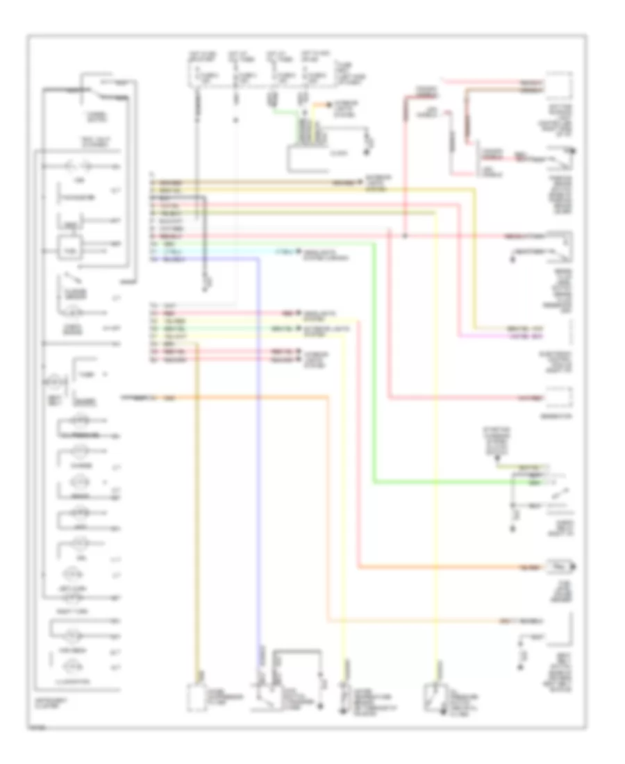
INSTRUMENT CLUSTER
Instrument Cluster Wiring Diagram for Suzuki Samurai JA 1992
List of elements for Instrument Cluster Wiring Diagram for Suzuki Samurai JA 1992:
- (base of driver's seat belt buckle)
- * exc. calif. & canada
- 4wd
- 4wd switch (transfer case)
- A15
- B13
- Brake
- Brake fluid level switch (brake fluid reservoir cap)
- Buzzer
- Canada models
- Cancel switch
- Charge
- Check engine
- Check relay (right i/p)
- Clock
- Daytime running light controller (right side of i/p)
- Drl
- Electronic control module (right i/p)
- Exterior lights system
- Fuel
- Fuel level gauge sender
- Fuse 3 15a
- Fuse 5 15a
- Fuse 6 20a
- Fuse 8 15a
- Fuse box (left side of dash)
- Generator
- Headlights system
- Headlights system (canada)
- High beam
- Hot at all times
- Hot in acc or ign
- Hot in ign or start
- Illumination
- Instrument cluster
- Interior lights system
- Left turn
- Mileage sensor
- Nca
- Noise suppressor filter
- Oil pressure
- Oil pressure switch (above oil filter)
- Parking brake switch (base of parking brake lever)
- Red
- Right turn
- Seat belt
- Seat belt switch
- Starting/ charging system (clutch switch)
- Tachometer
- Temp
- Timer
- Usa models
- Vss
- Water temperature sensor (on thermostat housing)
 English