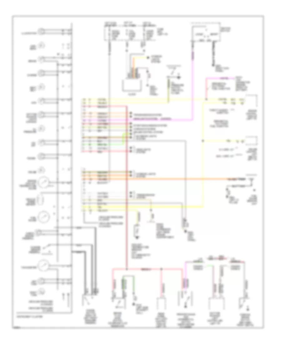
INSTRUMENT CLUSTER
Instrument Cluster Wiring Diagram for Suzuki Sidekick JX 1994
List of elements for Instrument Cluster Wiring Diagram for Suzuki Sidekick JX 1994:
- (canada)
- (left "c" pillar)
- 4wd
- A14
- A15
- Acc
- B13
- Brake
- Brake fluid level switch (on brake fluid reservoir)
- Canada models
- Cancel switch (right of left front speaker) (federal)
- Charge
- Check engine (federal)
- Cigar radio fuse 20a
- Clock
- Coolant temperature sending unit (in thermostat housing)
- Cruise
- Cruise control system
- Cruise control unit (below left i/p)
- Data link connector (engine) (front of battery)
- Daytime running light controller (left i/p)
- Daytime running lights (canada)
- Engine control module (left i/p)
- Engine coolant temperature gauge
- Exc. 4 spd a/t
- Exterior lights system
- Fuel gauge
- Fuel gauge sending unit
- Fuse box (left i/p)
- G116 (left side of safety wall)
- G200 (left kick panel)
- G203 (right kick panel)
- Headlights system
- High- beam
- Hot at all times
- Hot in acc or on
- Hot in on or start
- Ig-coil meter fuse 15a
- Ignition switch
- Illumination
- Instrument cluster
- Interior lights system
- Left turn
- Lock
- Mileage sensor (federal)
- Nca
- O/d off
- Oil pressure
- Oil pressure switch (above oil filter)
- Parking brake switch (between front seats)
- Power
- Proportioning and differential switch (near master cylinder)
- Radio noise supressor (left rear engine compartment)
- Rear wheel anti-lock control module (left i/p)
- Red
- Right turn
- Seat belt
- Sequential multiport fuel injection
- Start
- Starting/charging system
- Tachometer
- Tail dome fuse 15a
- Throttle body injection
- Transmissions system
- U.s. models
- Vehicle speed sensor
- Vehicles produced in canada
- Vehicles produced in japan
- W/ 4 spd a/t
- Warning systems
 English