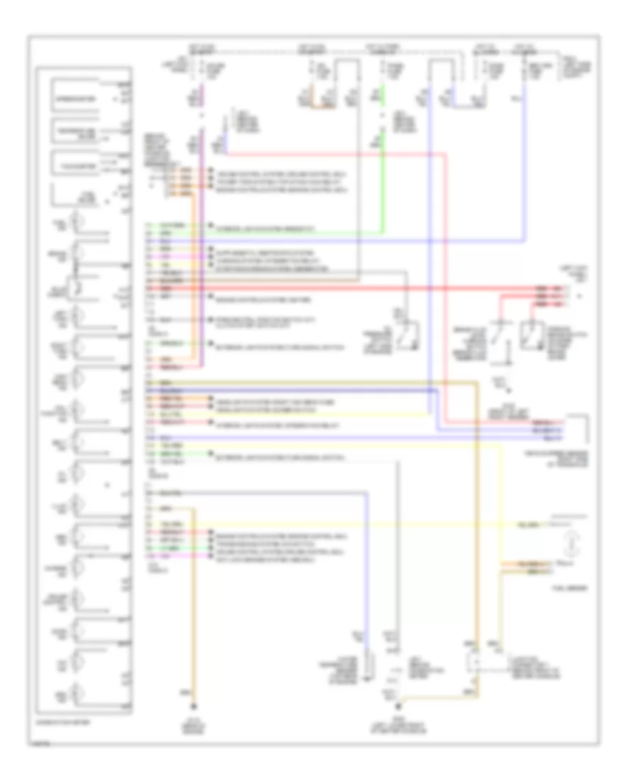
INSTRUMENT CLUSTER
Instrument Cluster Wiring Diagram for Toyota Celica GT 1998
List of elements for Instrument Cluster Wiring Diagram for Toyota Celica GT 1998:
- (behind front of center console) junction connector 7
- (left kick panel) j/b 1
- A10
- A11
- A13
- Abs ind
- Anti-lock brakes system (abs ecu)
- B10
- B11
- B13
- B14
- B15
- B16
- Belt ind
- Brake fluid level warning switch (brake fluid reservoir)
- Brake ind
- Bulb check
- C10
- C10 conn c
- C14
- C8 conn a
- C9 conn b
- Charge ind
- Combination meter
- Cruise control ind
- Cruise control system (cruise control ecu)
- Dome fuse 10a
- Door ind
- Engine controls system (engine control ecu)
- Engine controls system (igniter)
- Exterior lights system (turn signal switch)
- Fuel gauge
- Fuel ind
- Fuel sender
- G100 (front of left front fender)
- G115 (rear of engine)
- G302 (left lower front of center console)
- Gauge fuse 10a
- Headlights system (dimmer switch)
- Headlights system (right high beam fuse)
- High beam ind
- Hot at all times
- Hot in on or start
- Hot w/ park lamps on
- Ign fuse 7.5a
- Illum ind
- Interior lights system (integration relay)
- Interior lights system (rheostat)
- J/b 1 (left kick panel)
- J/b 3 (behind center of dash)
- J/b 3 (behind combination meter)
- Junction connector 7 (behind front of center console)
- Left turn ind
- Mal- function ind
- O/d ind
- Oil ind
- Oil pressure switch (left side of engine)
- Panel fuse 7.5a
- Park/neutral position switch (a/t) clutch start switch (m/t)
- Parking brake switch (on base of park brake lever)
- Power tops system (top stack main relay)
- R/b 2 (left side of engine compt)
- Red
- Right turn ind
- Speedometer
- Srs ind
- Srs wrn fuse 7.5a
- Starting/charging system (generator)
- Tachometer
- Temperature gauge
- Transmissions system (o/d switch)
- Vehicle speed sensor (right side of transaxle)
- Warning system (integration relay)
- Water temperature sender (top rear of engine)
 English