INSTRUMENT CLUSTER
Clock Wiring Diagram for Toyota Matrix XRS 2006

List of elements for Clock Wiring Diagram for Toyota Matrix XRS 2006:
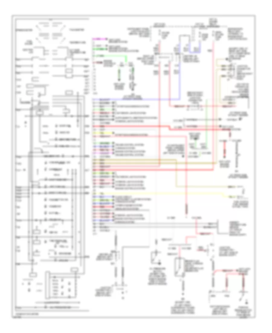
Instrument Cluster Wiring Diagram for Toyota Matrix XRS 2006
List of elements for Instrument Cluster Wiring Diagram for Toyota Matrix XRS 2006: