INSTRUMENT CLUSTER
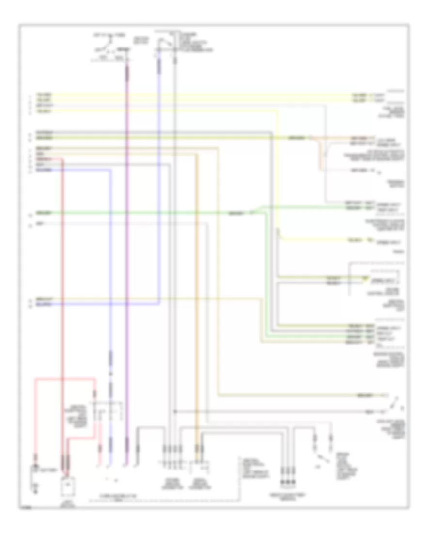
Instrument Cluster Wiring Diagram, VDO (1 of 2) for Volvo 850 GLT 1996

List of elements for Instrument Cluster Wiring Diagram, VDO (1 of 2) for Volvo 850 GLT 1996:
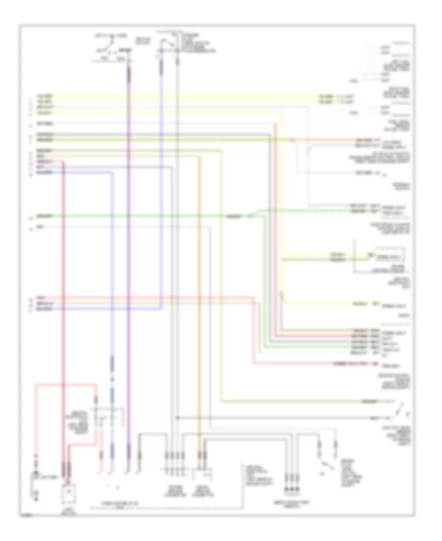
Instrument Cluster Wiring Diagram, VDO (2 of 2) for Volvo 850 GLT 1996
List of elements for Instrument Cluster Wiring Diagram, VDO (2 of 2) for Volvo 850 GLT 1996:
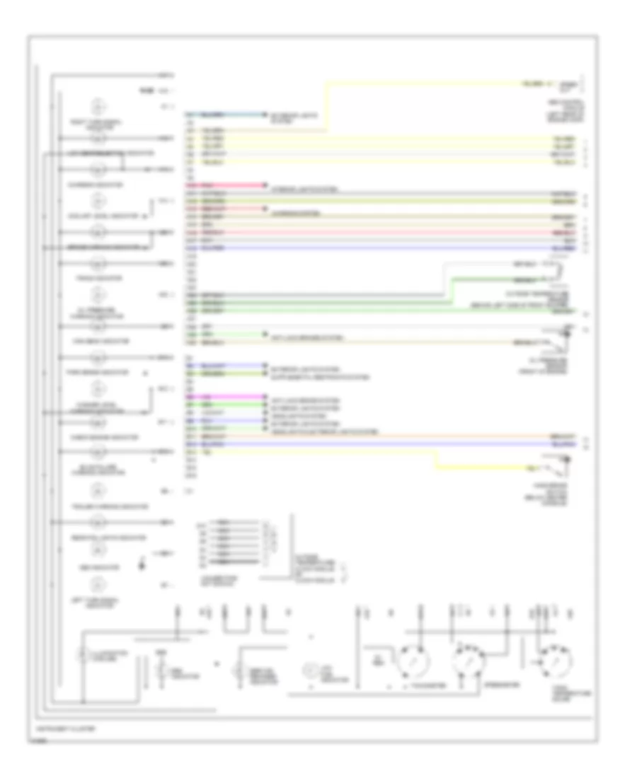
Instrument Cluster Wiring Diagram, Yasaki (1 of 2) for Volvo 850 GLT 1996
List of elements for Instrument Cluster Wiring Diagram, Yasaki (1 of 2) for Volvo 850 GLT 1996:
Instrument Cluster Wiring Diagram, Yasaki (2 of 2) for Volvo 850 GLT 1996
List of elements for Instrument Cluster Wiring Diagram, Yasaki (2 of 2) for Volvo 850 GLT 1996: