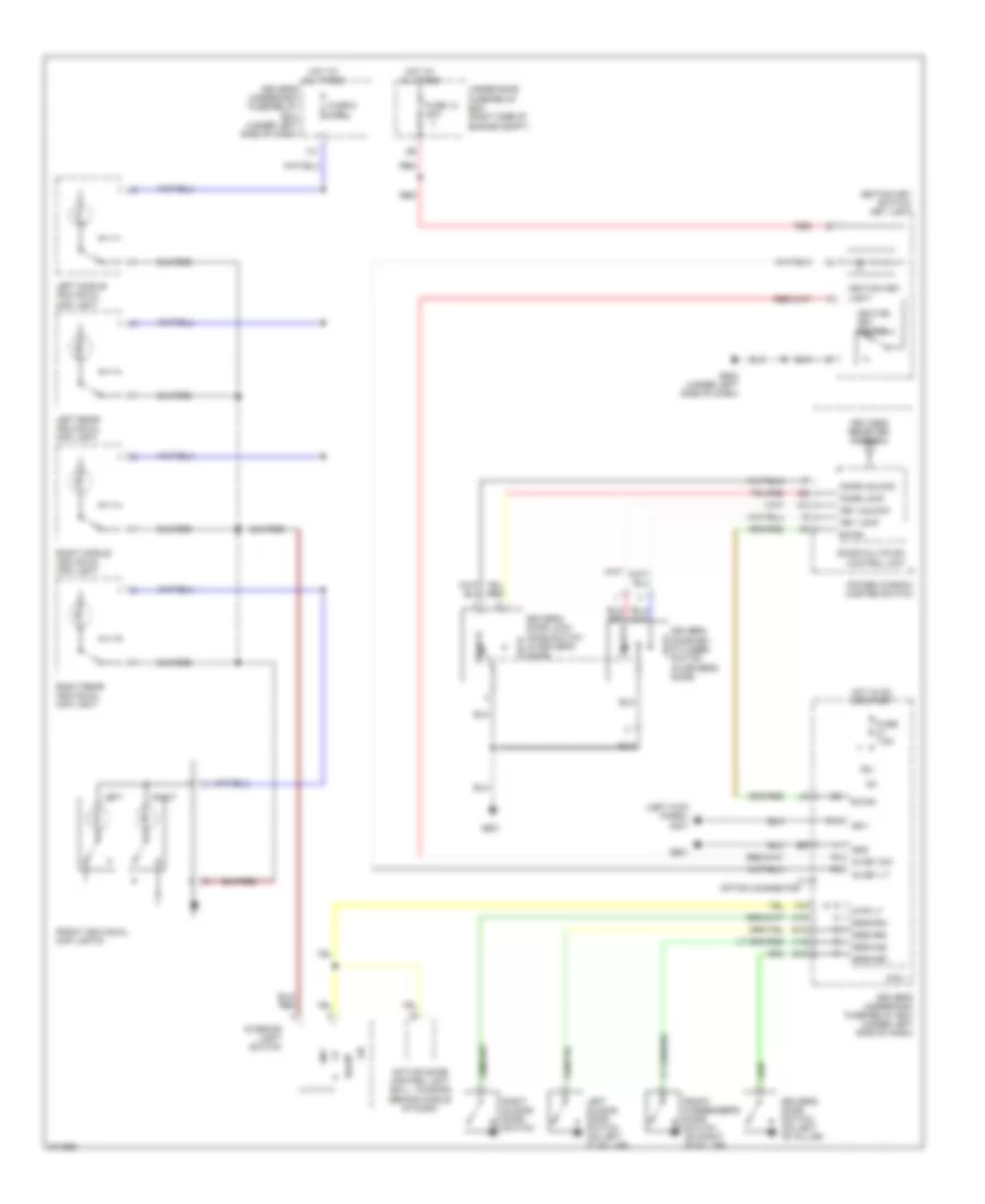
INTERIOR LIGHTS
Courtesy Lamps Wiring Diagram for Honda Odyssey EX 2005

List of elements for Courtesy Lamps Wiring Diagram for Honda Odyssey EX 2005:
- (behind middle of dash) active noise control unit
- (left rear of vehicle) g652
- (under left side of dash) g502
- A14
- B-can
- C11
- Cargo area light
- Cargo area light transistor
- Courtesy lt as
- Courtesy lt dr
- Door
- Driver's door courtesy light (ex, ex-l, touring)
- Driver's door switch (on left "b" pillar)
- Driver's underdash fuse/relay box (under left side of dash)
- Driver's vanity mirror light
- Drswas
- Drswdr
- Drswra
- Drswrd
- E14
- E15
- Ex-l, touring
- Front individual map lights
- Front passenger's door courtesy light (ex, ex-l, touring)
- Front passenger's door switch (on right "b" pillar)
- Front passenger's vanity mirror light
- Full
- Full latch switch
- Fuse 6 7.5a
- G601
- G701 (right "d" pillar)
- H12
- H13
- Hot at all times
- Inner power tailgate switch (touring)
- Instrument illumination circuit
- Interior light switch
- Interior light switch light
- Intrlt
- Left
- Left middle individual map light
- Left rear individual map light
- Left sliding door switch (on left "c" pillar)
- Lx, ex, ex-l
- Micu
- Micu-rear junction box (at right "d" pillar)
- Micu-rear junction box control unit
- N15
- Off
- Off door
- On door
- Option connector
- P15
- Power tailgate closer unit (middle of tailgate)
- Power tailgate control unit (at left "d" pillar)
- Red
- Right
- Right middle individual map light
- Right rear individual map light
- Right sliding door switch
- Seg3
- Tailgate latch switch (in tailgate)
- Touring
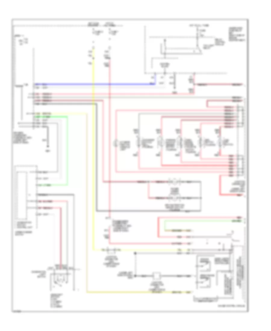
Entry Light Timer Wiring Diagram for Honda Odyssey EX 2005
List of elements for Entry Light Timer Wiring Diagram for Honda Odyssey EX 2005:
- (left kick panel) g401
- Active noise control unit (ex-l, touring) (behind middle of dash)
- B-can
- Door
- Door multiplex control unit
- Driver's door key cylinder switch (in driver's door)
- Driver's door lock knob switch (in driver's door)
- Driver's door switch (on left "b" pillar)
- Driver's underdash fuse/relay box (under left side of dash)
- Drswas
- Drswdr
- Drswra
- Drswrd
- E14
- E15
- Front individual map lights
- Front passenger's door switch (on right "b" pillar)
- Fuse 13 20a
- Fuse 6 7.5a
- Fuse 7.5a
- G502 (under left side of dash)
- G601
- Gnd
- H12
- H13
- Hot at all times
- Hot in on or start
- Ig key lt
- Ig key sw
- Ig1
- Ignition key light
- Ignition key switch
- Ignition key switch/ key light
- Interior light switch
- Intr lt
- Key lock
- Key unlock
- Keyless receiver antenna
- Knob lock
- Knob unlock
- Left
- Left middle individual map light
- Left rear individual map light
- Left sliding door switch (on left "c" pillar)
- Lock
- Micu
- Off
- P14
- Power window master switch
- Red
- Right
- Right middle individual map light
- Right rear individual map light
- Right sliding door switch
- Sg-1
- T1 option connector
- Under-hood fuse/relay box (right side of engine compt)
- Unlock
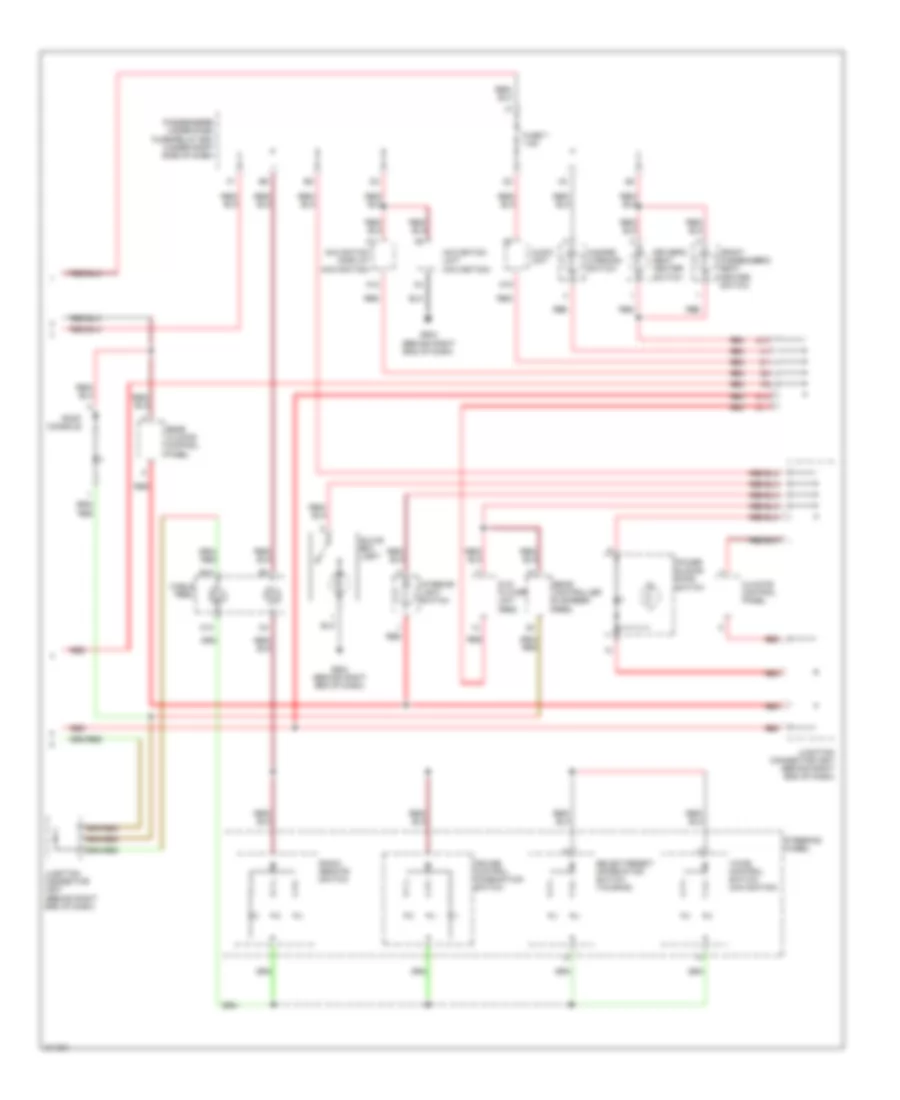
Instrument Illumination Wiring Diagram, EX, EX-L, Touring (1 of 2) for Honda Odyssey EX 2005
List of elements for Instrument Illumination Wiring Diagram, EX, EX-L, Touring (1 of 2) for Honda Odyssey EX 2005:
- (under left side of dash) g502
- A/t gear position console light
- A18
- A19
- A20
- A21
- A25
- Aps switch (touring)
- B-can
- B12
- Brightening switch
- Combination light switch
- Combination switch control unit
- Control block
- D11
- Dash lights brightness controller
- Dash- board power tailgate switch (touring)
- Dimming switch
- Driver's underdash fuse/relay box (under left side of dash)
- Driving position memory switch (touring)
- E14
- Fuse 15a
- Fuse 21 7.5a
- Fuse 7 7.5a
- G202
- G601
- Gauge control module
- Headlight switch 0) off 1) hi beam 2) auto 3) lo beam
- Hot at all times
- Hot in on or start
- Ig1
- J19
- Junction connector c501 (under left side of dash)
- Junction connector c503 (under middle of dash)
- K10
- Micu
- Moonroof switch (ex-l, touring)
- Multi-information display unit
- N28
- N42
- Parking/ back-up sensor switch (touring)
- Passenger's under-dash fuse/relay box (under right side of dash)
- Power mirror switch
- Red
- Relay control module
- Taillight relay
- Transceiver area network body controller
- Under-hood fuse relay box (right side of engine compartment)
- Vbu
- Vsa off switch
- Wiper/washer switch
- X27
- X34
- X35
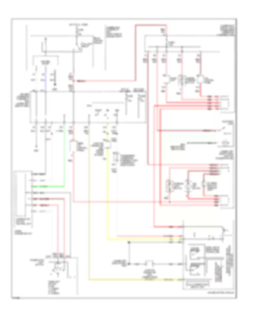
Instrument Illumination Wiring Diagram, EX, EX-L, Touring (2 of 2) for Honda Odyssey EX 2005
List of elements for Instrument Illumination Wiring Diagram, EX, EX-L, Touring (2 of 2) for Honda Odyssey EX 2005:
- A11
- A12
- A19
- Audio unit
- B10
- C10
- Cable reel
- Climate control panel
- Cruise control combination switch
- Driver's seat heater switch
- Dvd player unit (res)
- E11
- E12
- Front passenger's seat heater switch
- Fuse 7 7.5a
- G10
- G504 (behind right end of dash)
- Glove box light
- Hazard warning switch
- Interior light switch
- Junction connector c507 (behind right end of dash)
- Navigation display (navigation)
- Navigation unit (navigation)
- Passenger's under-dash fuse/relay box (under right side of dash)
- Power sliding door switch
- Radio remote switch
- Rear climate control panel
- Rear controller & screen (res)
- Red
- Roof console
- Select/reset/ information switch (touring)
- Steering wheel
- Voice control switch (navigation)
Instrument Illumination Wiring Diagram, LX for Honda Odyssey EX 2005
List of elements for Instrument Illumination Wiring Diagram, LX for Honda Odyssey EX 2005:
- (under left side of dash) g502
- (under left side of dash) junction connector c502
- (under right side of dash) passenger's under-dash fuse/relay box
- A/c control panel
- A/t gear position console light
- A12
- A19
- A20
- A21
- A25
- Audio unit
- B-can
- B12
- Brightening switch
- Combination light switch
- Combination switch control unit
- Control block
- D11
- Dash lights brightness controller
- Dimming switch
- Driver's underdash fuse/relay box (under left side of dash)
- E12
- E14
- Fuse 15a
- Fuse 7 7.5a
- Fuse 7.5a
- G10
- G202
- G504 (behind right end of dash)
- G601
- Gauge control module
- Glove box light
- Hazard warning switch
- Headlight switch 0) off 1) hi beam 2) auto 3) lo beam
- Hot at all times
- Hot in on or start
- Ig1
- Interior light switch
- Junction connector c503 (under middle of dash)
- K10
- Micu
- Multi-information display unit
- N28
- N42
- Passenger's under-dash fuse/relay box (under right side of dash)
- Rear a/c control panel
- Red
- Relay control module
- Taillight relay
- Transceiver area network body controller
- Under-hood fuse relay box (right side of engine compt)
- Vbu
- Vsa off switch
- Wiper/ washer switch
- X27
- X34
- X35