INTERIOR LIGHTS
Courtesy Lamps Wiring Diagram for Mercury Mystique LS 1997

List of elements for Courtesy Lamps Wiring Diagram for Mercury Mystique LS 1997:
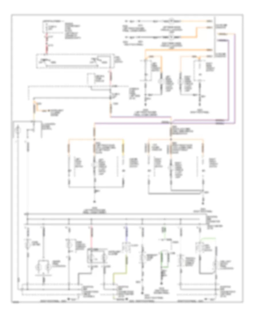
Instrument Illumination Wiring Diagram for Mercury Mystique LS 1997
List of elements for Instrument Illumination Wiring Diagram for Mercury Mystique LS 1997: