INTERIOR LIGHTS
Courtesy Lamps Wiring Diagram, Evolution (1 of 2) for Mitsubishi Lancer GT 2012

List of elements for Courtesy Lamps Wiring Diagram, Evolution (1 of 2) for Mitsubishi Lancer GT 2012:
- (in left "c" pillar)
- (left side of luggage compt) g11
- Analog
- C-301
- C-309
- C-311
- C-313
- C-315
- C-316
- Can drive circuit
- Circuit can drive
- Circuit interface
- Circuit interface analog
- Computer data lines system
- D-16
- Etacs-ecu (on rear of junction block behind left end of dash)
- F-27
- Fusible link 34 80a
- Fusible link box
- G4 (behind right kick panel)
- Hot at all times
- Ig1 relay
- Interface circuit
- Key reminder switch
- Left front door switch (in left "b" pillar)
- Left rear door switch
- Luggage compartment light
- Nca
- Off
- Pnk
- Red
- Right front door switch (in right "b" pillar)
- Right rear door switch (in right "c" pillar)
- Trunk lid latch
Courtesy Lamps Wiring Diagram, Evolution (2 of 2) for Mitsubishi Lancer GT 2012
List of elements for Courtesy Lamps Wiring Diagram, Evolution (2 of 2) for Mitsubishi Lancer GT 2012:
- (behind right kick panel) g4
- C-105
- Can transceiver circuit
- Combination meter
- Cpu
- Door
- Front dome light
- Joint connector (can1) (left top of dash)
- Lcd (each door)
- Off
- Pnk
- Rear dome light (w/o sunroof)
- Red
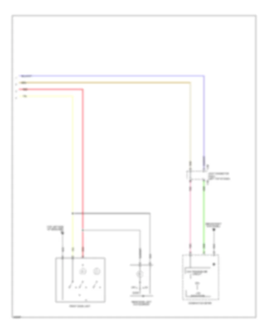
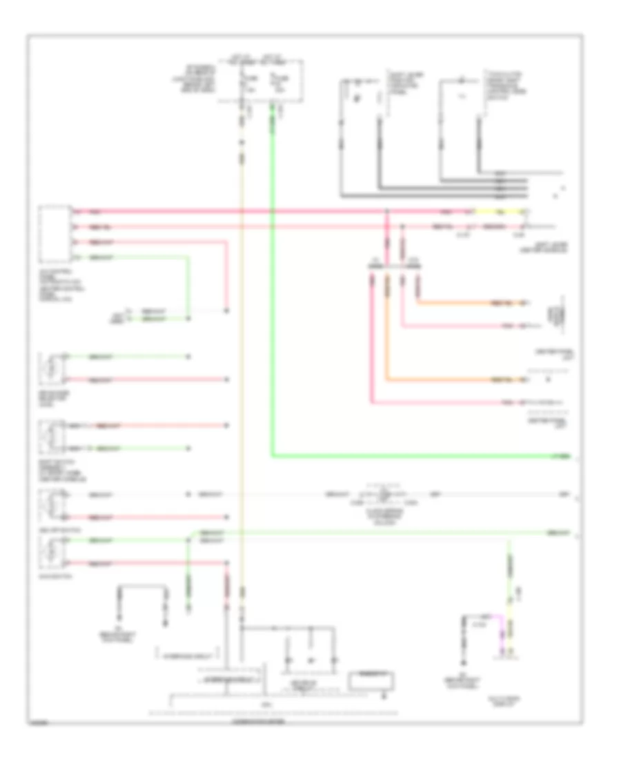
Courtesy Lamps Wiring Diagram, Except Evolution (1 of 2) for Mitsubishi Lancer GT 2012
List of elements for Courtesy Lamps Wiring Diagram, Except Evolution (1 of 2) for Mitsubishi Lancer GT 2012:
- (at left "c" pillar) g10
- (in left "c" pillar)
- (not used)
- C-301
- C-309
- C-311
- C-313
- C-315
- C-316
- Can drive circuit
- Circuit
- Circuit interface
- Circuit interface analog
- Computer data lines system
- D-11
- D-15
- Etacs-ecu (on rear of junction block, behind left end of dash)
- F-23
- F-30
- Fusible link 34 80a
- Fusible link box
- G21 (on liftgate)
- G4 (behind right kick panel)
- G9 (at right "c" pillar)
- Hatchback
- Hot at all times
- Interface analog
- Interface circuit
- Key reminder switch (w/o kos)
- Left front door switch (in left "b" pillar)
- Left rear door switch
- Lift gate switch
- Luggage compartment light
- Nca
- Off
- Pnk
- Red
- Right front door switch (in right "b" pillar)
- Right rear door switch (in right "c" pillar)
- Sedan
- Trunk lid lock actuator (center rear of trunk lid)
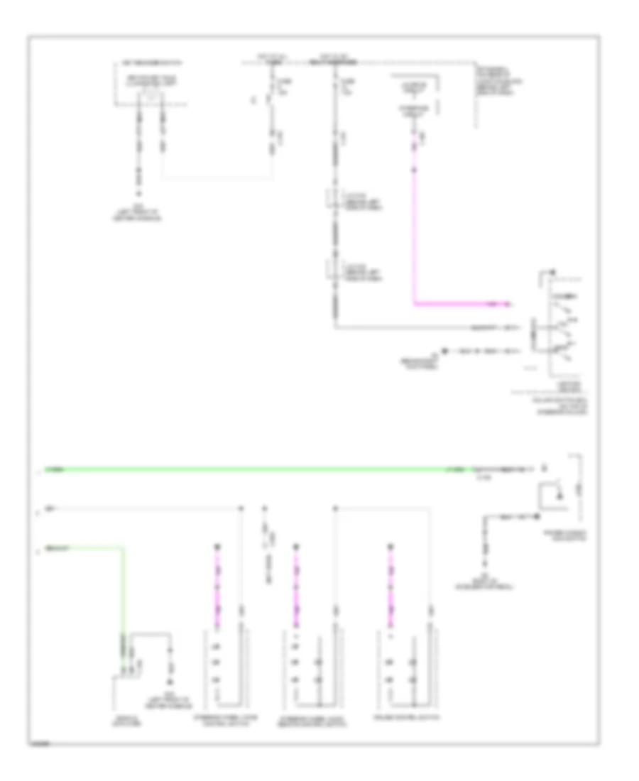
Courtesy Lamps Wiring Diagram, Except Evolution (2 of 2) for Mitsubishi Lancer GT 2012
List of elements for Courtesy Lamps Wiring Diagram, Except Evolution (2 of 2) for Mitsubishi Lancer GT 2012:
- (behind right kick panel) g4
- (top left side of headliner) g7
- C-06
- Can transceiver circuit
- Combination meter
- Cpu
- Door
- Front dome light
- Joint connector (can1) (left top of dash)
- Lcd (each door)
- Off
- Pnk
- Rear dome light (w/o sunroof)
- Red
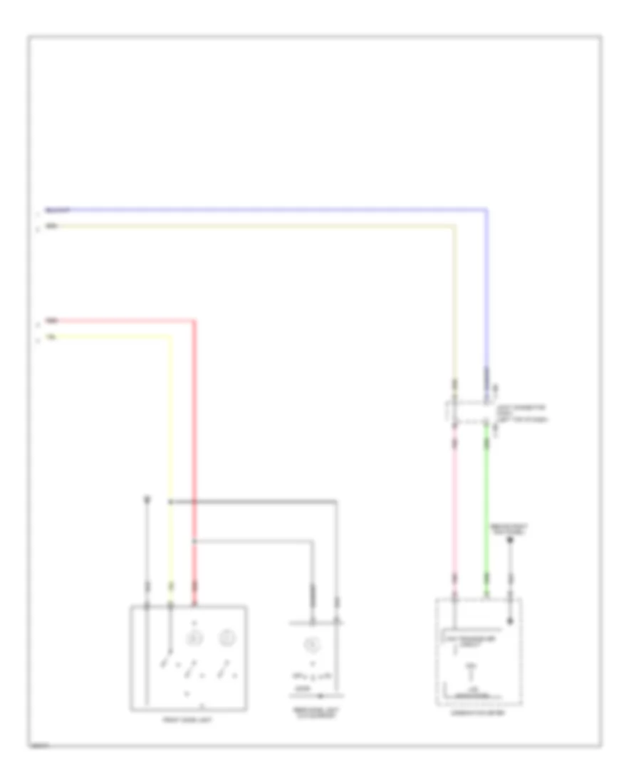
Instrument Illumination Wiring Diagram, Evolution for Mitsubishi Lancer GT 2012
List of elements for Instrument Illumination Wiring Diagram, Evolution for Mitsubishi Lancer GT 2012:
- (left front engine compt) g17
- (not used)
- (on top of steering column) column switch ecu
- A/c control panel
- Asc off switch
- Audio
- Awc switch (w/ steering wheel audio remote control switch)
- Awc switch (w/o steering wheel audio remote control switch)
- C-106
- C-107
- C-108
- C-12
- C-128
- C-13
- C-130
- C-202
- C-205
- C-206
- C-301
- C-315
- C-317
- C-33
- Center panel unit
- Clock spring (in steering column)
- Column ecu
- Combination meter
- Cpu
- Cruise control switch
- Etacs-ecu (on rear of junction block, behind left end of dash)
- Fuse 30a
- Fuse 7.5a
- Fuse 9 15a
- G17 (left front engine compt)
- G4 (behind right kick panel)
- G6 (behind center of dash)
- Head
- Heated seat switch
- Hot at all times
- Hot w/ ig1 relay energized
- Ignition key hole illumination light
- Ill
- Interface circuit
- J/c c-101
- Key reminder switch
- Led drive circuit
- Lighting switch
- Lin drive circuit
- Multi vision display
- Nca
- Pnk
- Power window main switch
- Radio & cd player
- Rheostat
- Shift lever (center console)
- Shift lever position indicator panel
- Steering wheel audio remote control switch
- Steering wheel voice control switch
- Switch panel
- Tail
- Twin clutch sport shift transaxle control mode switch
- W/ mmcs
- W/o mmcs
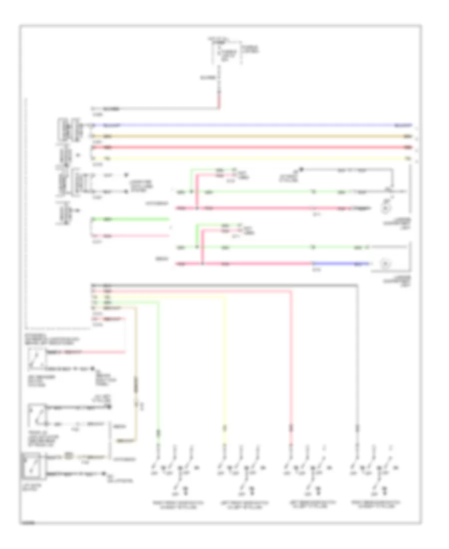
Instrument Illumination Wiring Diagram, Except Evolution (1 of 2) for Mitsubishi Lancer GT 2012
List of elements for Instrument Illumination Wiring Diagram, Except Evolution (1 of 2) for Mitsubishi Lancer GT 2012:
- (not used)
- A/c control panel (automatic a/c)
- Asc off switch
- Audio switch
- Awc switch
- C-103
- C-105
- C-127
- C-204
- C-205
- C-315
- C-317
- C-49
- Center panel unit
- Clock spring (in steering column)
- Combination meter
- Cpu
- Drive mode selector (awd)
- Etacs-ecu (on rear of junction block, behind left end of dash)
- Fuse 30a
- Fuse 7.5a
- G4 (behind right kick panel)
- Heater control panel (manual a/c)
- Hot at all times
- Ill
- Interface circuit
- Led drive circuit
- Multivision display
- Nca
- Panel
- Pnk
- Rheostat
- Shift lever (center console)
- Shift lever position indicator panel
- Shift switch assembly (w/ sport mode) (center console)
- Twin clutch sport shift transaxle control mode switch
- W/ mmcs
- W/o mmcs
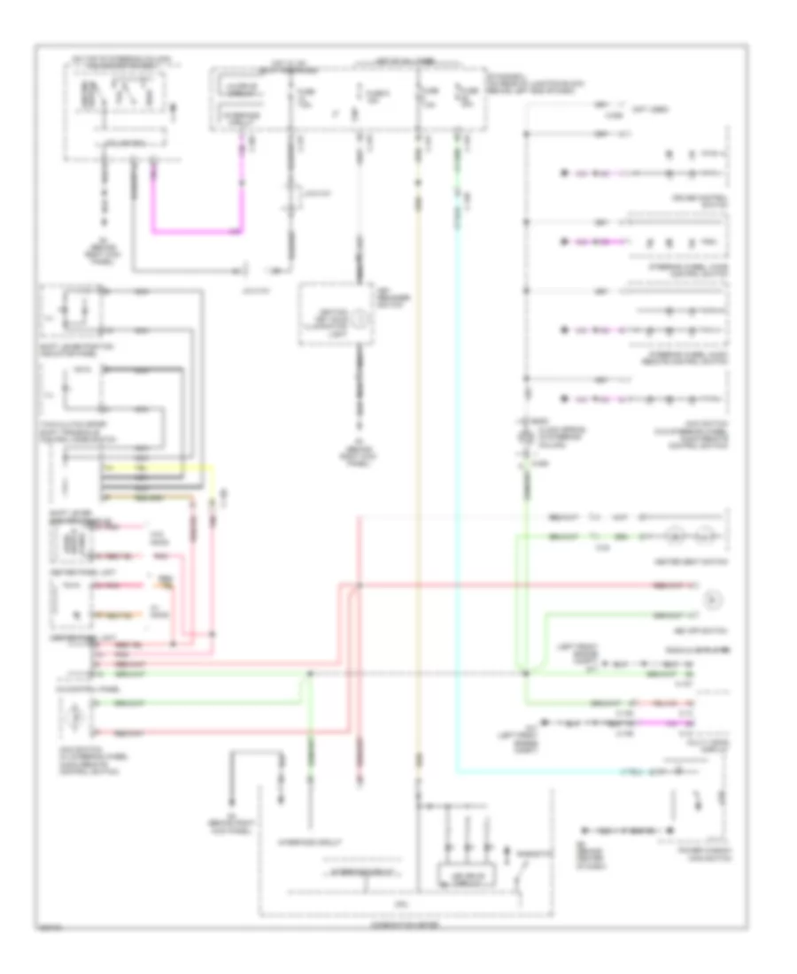
Instrument Illumination Wiring Diagram, Except Evolution (2 of 2) for Mitsubishi Lancer GT 2012
List of elements for Instrument Illumination Wiring Diagram, Except Evolution (2 of 2) for Mitsubishi Lancer GT 2012:
- (not used)
- C-104
- C-125
- C-209
- C-301
- C-315
- C-317
- Column ecu
- Column switch ecu (on top of steering column)
- Cpu
- Cruise control switch
- Dimmer
- Etacs-ecu (on rear of junction block, behind left end of dash)
- Fuse 15a
- Fuse 7.5a
- G15 (left front of center console)
- G4 (behind right kick panel)
- G5 (right of accelerator pedal)
- Head
- Hot at all times
- Hot w/ ig1 relay energized
- Ignition key hole illumination light
- Interface circuit
- J/c c-03 (behind left side of dash)
- Key reminder switch
- Lighting switch
- Lin drive circuit
- Nca
- Power window main switch
- Radio & cd player
- Steering wheel audio remote control switch
- Steering wheel voice control switch
- Tail