INTERIOR LIGHTS
Courtesy Lamps Wiring Diagram for Nissan Maxima SE 1997

List of elements for Courtesy Lamps Wiring Diagram for Nissan Maxima SE 1997:
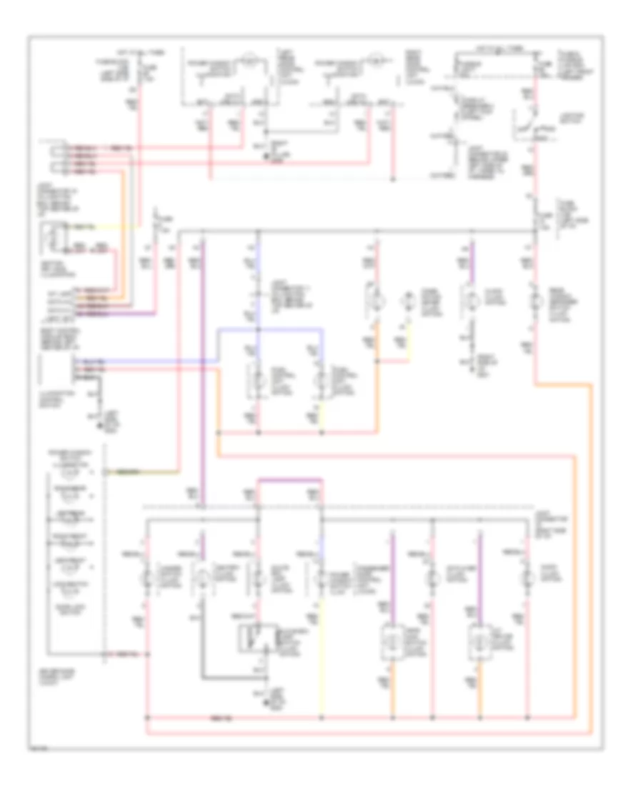
Instrument Illumination Wiring Diagram for Nissan Maxima SE 1997
List of elements for Instrument Illumination Wiring Diagram for Nissan Maxima SE 1997: