
Isuzu Oasis LS 1997 - 1997 ENGINE PERFORMANCE Self-Diagnostics
Isuzu Oasis LS 1997 - INTRODUCTION
If no faults were found while performing basic diagnostic procedures in the BASIC TESTING article, proceed with self-diagnostics. If no Diagnostic Trouble Codes (DTCs) or only pass codes are present after entering self-diagnostics, proceed to the TESTS W/O CODES article for diagnosis by symptom (i.e., ROUGH IDLE, NO START, etc.).
Isuzu Oasis LS 1997 - SELF-DIAGNOSTIC SYSTEM HARD FAILURES
Hard failures cause Malfunction Indicator Light (MIL) to illuminate and remain on until problem is repaired. If light comes on and remains on (light may flash) during vehicle operation, cause of malfunction must be determined by retrieving DTCs and using DIAGNOSTIC TROUBLE CODES. See RETRIEVING CODES . If a sensor fails, control unit will use a substitute value in its calculations to continue engine operation. In this condition, commonly known as limp-in mode, the vehicle runs but driveability will not be optimum.
Isuzu Oasis LS 1997 - INTERMITTENT FAILURES
Intermittent failures may cause Malfunction Indicator light (MIL) to flicker or illuminate and go out after the intermittent fault goes away. The corresponding DTC will be retained in Powertrain Control Module (PCM) memory. If related fault does not reoccur within 50 starter operations, related DTC will be erased from PCM memory. Intermittent failures may be caused by sensor, connector or wiring related problems. See INTERMITTENTS in the TESTS W/O CODES article.
Isuzu Oasis LS 1997 - MALFUNCTION INDICATOR LIGHT (MIL)
All models are equipped with an MIL. As a bulb check, light illuminates for 2 seconds when ignition is on and engine is not running. MIL also illuminates when a system failure has been detected and a corresponding DTC has been set in Powertrain Control Module (PCM) memory. Not all trouble codes will activate MIL. If MIL is on and no DTCs are in memory, problem may be intermittent. See INTERMITTENTS in the TESTS W/O CODES article.
Isuzu Oasis LS 1997 - RETRIEVING CODES
NOTE: Self-diagnostics are limited when accessing codes using MIL. For complete self-diagnostic capabilities an OBD-II compliant scan tool or Honda PGM Tester is required.
Turn ignition off. Connect Honda PGM Tester or OBD-II scan tool to 16-pin Data Link Connector (DLC). DLC is located behind passenger side of center console.
Turn ignition on. If using Honda PGM Tester, follow tester prompts. Diagnostic trouble code tests are not needed. If using scan tool, check for and note any DTCs. Also check for and note Freeze Frame Data. See DIAGNOSTIC TROUBLE CODE IDENTIFICATION and proceed to appropriate DTC testing.
CAUTION: DO NOT attempt any connection to 3-pin Data Link Connector (DLC) located near 2-pin service check connector.
Codes can also be accessed by using MIL. Connect SCS Service Connector (07PAZ-0010100) to 2-pin service check connector. Service check connector is located under passenger side of instrument panel near center console.
Turn ignition on. Diagnostic Trouble Codes (DTCs) will be indicated by a series of long and short flashes on MIL. The number of long flashes indicates the number in the tens column. The number of short flashes indicates the number in the ones column. For example, 4 long flashes followed by 3 short flashes would indicate DTC 43. See DIAGNOSTIC TROUBLE CODE IDENTIFICATION and proceed to appropriate DTC testing.
Isuzu Oasis LS 1997 - FREEZE FRAME DATA
Freeze frame data indicates engine operating conditions when the first malfunction, misfire or fuel trim malfunction was detected.
Isuzu Oasis LS 1997 - PCM RESET PROCEDURE/CLEARING DTCS
NOTE: Before disconnecting battery or removing fuse, obtain anti-theft code for radio from vehicle owner. After battery or fuse is reconnected, CODE will appear on radio display. Enter 5-digit code to restore radio operation. If code is entered incorrectly 3 times, leave radio on at least one hour, then enter code correctly. Any time radio power is lost, pre-selected radio stations will have to be reset. For more information, see owners manual.
Powertrain Control Module (PCM) can be reset, which clears DTCs, using a Honda PGM tester or OBD-II scan tool following manufacturer's instructions. DTCs can also be cleared by removing fuse. Turn ignition off. Remove BACK UP (7.5-amp) fuse from underhood fuse/relay block. Leave fuse out for at least 10 seconds. Reset radio anti-theft code, pre-selected radio stations and clock.
Isuzu Oasis LS 1997 - PCM LOCATION
NOTE: Different Honda models are equipped with either an Engine Control Module (ECM) or a Powertrain Control Module (PCM). ECM will be referred to as a PCM.
PCM is located under passenger side footwell carpet behind PCM cover.
Isuzu Oasis LS 1997 - SUMMARY
If no hard fault codes (or only pass codes) exist, driveability symptoms exist, or intermittent codes exist, proceed to the TESTS W/O CODES article for diagnosis by symptom (i.e., ROUGH IDLE, NO START, etc.) or intermittent diagnostic procedures.
Isuzu Oasis LS 1997 - TEST EQUIPMENT
All voltage tests should be performed with a Digital Volt-Ohmmeter (DVOM) with a minimum 10-megohm input impedance, unless specifically stated differently in testing procedure.
Use Backprobe Set (07SAZ-001000A ) (2 required) to backprobe Powertrain Control Module (PCM) when directed by testing. See Fig. 1 . For PCM connector terminal identification, see CONNECTOR IDENTIFICATION . DO NOT puncture wire insulation. Place scan tool probe into contact with terminal, from terminal side of wiring harness connectors in engine compartment. For female connectors, just touch terminal lightly with scan tool probe. DO NOT insert probe into terminal.
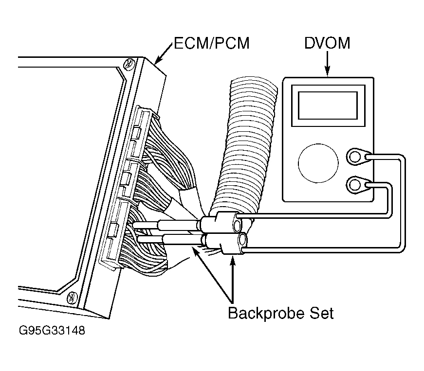
Fig. 1: Isuzu Oasis LS 1997 - Component Locations - Using Backprobe Set
Isuzu Oasis LS 1997 - CONNECTOR IDENTIFICATION
Fig. 2: Isuzu Oasis LS 1997 - Component Locations - PCM Harness Connector Terminals

Fig. 3: Isuzu Oasis LS 1997 - Component Locations - Data Link Connector (DLC) Connector Terminals

Isuzu Oasis LS 1997 - DIAGNOSTIC TROUBLE CODE IDENTIFICATION
NOTE: Not all codes apply to all models.
Isuzu Oasis LS 1997 DIAGNOSTIC TROUBLE CODE (DTC) TEST DIRECTORY
DTC MIL/"D4" Code (1) Description P0107 3 MAP Sensor Circuit Low Voltage Input P0108 3 MAP Sensor Circuit High Voltage Input P0111 10 Intake Air Temp. (IAT) Sensor Circuit Range/Performance Problem P0112 10 IAT Circuit Low Voltage Input P0113 10 IAT Circuit High Voltage Input P0116 86 Engine Coolant Temperature (ECT) Sensor Range/Performance Problem P0117 6 ECT Circuit Low Voltage Input P0118 6 ECT Circuit High Voltage Input P0122 7 Throttle Position (TP) Circuit Low Voltage Input P0123 7 TP Circuit High Voltage Input P0131 1 Front Heated Oxygen Sensor-1 (HO2S-1) Low Voltage P0132 1 Front HO2S-1 High Voltage P0133 61 Front HO2S-1 Slow Response P0135 41 Front HO2S-1 Heater Circuit Malfunction P0137 63 Rear Heated Oxygen Sensor-2 (HO2S-2) Low Voltage P0138 63 Rear HO2S-2 High Voltage P0139 63 Rear HO2S-2 Slow Response P0141 65 Rear HO2S-2 Heater Circuit Malfunction P0171 45 System Too Lean P0172 45 System Too Rich P0301 71 Cylinder No. 1 Misfire Detected P0302 72 Cylinder No. 2 Misfire Detected P0303 73 Cylinder No. 3 Misfire Detected P0304 74 Cylinder No. 4 Misfire Detected P0335 4 Crankshaft Position (CKP) Sensor No Signal Input P0336 4 CKP Sensor Circuit Range/Performance Problem P0401 80 EGR Insufficient Flow Detected P0420 67 Catalyst System Efficiency Below Threshold P0441 92 (2) EVAP Control System Insufficient Purge Flow P0500 17 Vehicle Speed Sensor (VSS) Circuit Malfunction P0501 17 VSS Circuit Range/Performance Problem P0505 14 Idle Control System Malfunction (3) 70/- (1) Automatic Transmission (3) 70/15 (1) Automatic Transmission (3) 70/9 (1) Automatic Transmission (3) 70/11 (1) Automatic Transmission (3) 70/41 (1) Automatic Transmission (3) 70/7 (1) Automatic Transmission (3) 70/8 (1) Automatic Transmission P1106 13 Barometric Pressure (BARO) Sensor Circuit Range/Performance Problem P1107 13 BARO Sensor Circuit Low Voltage Input P1108 13 BARO Sensor Circuit High Voltage Input P1121 7 Throttle Position (TP) Lower Than Expected P1122 7 Throttle Position (TP) Higher Than Expected P1128 5 Manifold Absolute Pressure (MAP) Lower Than Expected P1129 5 Manifold Absolute Pressure (MAP) Higher Than Expected P1297 20 Electrical Load Detector (ELD) Circuit Low Voltage Input P1298 20 ELD Circuit High Voltage Input P1300 71-76 (4) Random Misfire Detected P1359 8 CKP/TDC Sensor Connector Poor Connection P1361 8 Top Dead Center (TDC) Sensor Intermittent Interruption P1362 8 TDC Sensor No Signal P1381 9 Cylinder Position (CYP) Sensor Intermittent Interruption P1382 9 CYP Sensor No Signal P1459 92 EVAP Purge Flow Switch Malfunction P1491 12 EGR Valve Insufficient Lift Detected P1498 12 EGR Valve Lift Sensor High Voltage P1508 14 Idle Air Control (IAC) Valve Circuit Failure P1607 - PCM Internal Failure P1705 70/5 (1) A/T Gear Position Switch Circuit Malfunction P1706 70/6 (1) A/T Gear Position Switch Circuit Malfunction (3) 70/1 (1) Automatic Transmission (3) 70/2 (1) Automatic Transmission (3) 70/16 (1) Automatic Transmission
DTC retrieved from MIL (engine controls) or A/T position "D4" indicator (A/T controls) flashes when SCS service connector is connected. MIL and "D4" indicator may flash simultaneously. Diagnosis MIL DTCs before "D4" DTCs. (1)
Does not apply to all models. - vehicle underhood EMISSION GROUP IDENTIFICATION label. (2)
See the AUTO TRANS DIAGNOSIS - AOYA, BOYA, MPJA article. (3)
DTC P1300 or some of DTCs P0301 through P0306. (4)
Isuzu Oasis LS 1997 - CIRCUIT TESTS
NOTE: Different Honda models are equipped with either an Engine Control Module (ECM) or a Powertrain Control Module (PCM). ECM will be referred to as a PCM.
NOTE: When there is no DTC stored, MIL will stay on if the SCS service connector is connected and ignition switch is on.
When directed by testing procedure to install test equipment, see TEST EQUIPMENT .
Isuzu Oasis LS 1997 - MALFUNCTION INDICATOR LIGHT (MIL) MALFUNCTION Intermittent Symptom
If symptom is intermittent, check for loose fuse No. 1 BACK UP LIGHTS (10-amp). Fuse is located in underdash fuse/relay box. Also check for poor connection at PCM connector terminal A18 or an intermittent open in wire between PCM connector terminal A18 and gauge assembly. See the WIRING DIAGRAMS article.
Isuzu Oasis LS 1997 - Malfunction Indicator Light (MIL) Never Comes On, Even For 2 Seconds After Ignition Is Turned On
- Turn ignition on. If low oil pressure light is on, go to next step. If light is not on, replace fuse No. 1 BACK UP LIGHTS (10-amp). Repair short or open in wire between fuse and gauge assembly. See the WIRING DIAGRAMS article.
- Try to start engine. If engine starts, go to next step. If engine does not start, turn ignition on. Measure voltage between ground and PCM connector terminal A10 (Black wire) and terminal A23 (Black wire) individually. See Fig. 2 . If less than one volt exists, substitute a known-good PCM and recheck. If symptom or indication goes away, replace original PCM. If one volt or more exists, repair open in Black wire(s) between PCM and ground (G101), located at left side of intake manifold.
- Turn ignition off. Using jumper wire, connect PCM connector terminal A18 to ground. See Fig. 2 . Turn ignition on. If MIL comes on, substitute a known-good PCM and recheck. If symptom or indication goes away, replace original PCM. If MIL does not come on, replace MIL bulb and/or repair open in wire between PCM connector terminal A18 and gauge assembly. See the WIRING DIAGRAMS article.
NOTE: MIL will stay on when no DTC is stored and SCS service check connector is connected and ignition is on.
Isuzu Oasis LS 1997 - Malfunction Indicator Light (MIL) Stays On Or Comes On After 2 Seconds
- If symptom is intermittent, check for:
- A loose fuse No. 33 ECU (10-amp) located in underhood fuse/relay box.
- A loose fuse No. 2 FUEL PUMP (15-amp), located in underdash fuse/relay box.
- An intermittent short in wire between PCM connector "C" terminal C7 and service check connector.
- An intermittent short in wire between PCM connector "A" terminal A18 and gauge assembly.
- An intermittent short in wire between PCM connector "D" terminal D4 and MAP sensor.
- An intermittent short in wire between PCM connector "D" terminal D10, TP sensor, EGR valve lift sensor (if equipped).
- A faulty PGM-FI main relay.
Perform repairs as necessary and recheck MIL operation. If no problems are found, go to next step.
- Connect scan tool to DLC connector. Turn ignition on. Read DTCs (if present). See RETRIEVING CODES . If DTCs are present, go to DIAGNOSTIC TROUBLE CODE IDENTIFICATION . After identifying DTC, go to appropriate Diagnostic Trouble Code (DTC) test. If DTCs are not present, go to next step.
- Turn ignition off. Connect SCS service connector to service check connector. See RETRIEVING CODES . Turn ignition on. If DTCs are not present using MIL, go to next step. If DTCs are present using MIL, repair open or short in wire between PCM connector terminal C8 and DLC. See Fig. 2 . See the WIRING DIAGRAMS article. Go to DIAGNOSTIC TROUBLE CODE IDENTIFICATION . After identifying DTC, go to appropriate Diagnostic Trouble Code (DTC) test.
- Attempt to start engine. If engine starts, go to next step. If engine does not start, go to step 7).
- Turn ignition off. Turn ignition on. Measure voltage between PCM connector terminal C7 (Red wire) and terminal D11 (Green/Blue wire). See Fig. 2 . If approximately 5 volts exists, go to next step. If approximately 5 volts does not exist, repair short to ground in wire between PCM connector terminal C7 and service check connector. See the WIRING DIAGRAMS article.
- Turn ignition off. Disconnect PCM 32-pin connector "A". See Fig. 2 . Turn ignition on. If MIL is on, repair short to ground in wire between PCM connector terminal A18 and MIL. See the WIRING DIAGRAMS article. If MIL is not on, substitute a known-good PCM and recheck. If symptom or indication goes away, replace original PCM.
- Inspect fuse No. 33 ECU (PCM) (10-amp). Fuses are located in underhood fuse/relay box. If fuse is okay, go to next step. If fuse is open, repair short in wire between fuse and PGM-FI main relay. See the WIRING DIAGRAMS article. Replace fuse.
- Inspect fuse No. 2 FUEL PUMP (15-amp). Fuses are located in underdash fuse/relay box. If fuse is okay, go to next step. If fuse is open, repair short in wire between fuse and PGM-FI main relay. See the WIRING DIAGRAMS article. Replace fuse.
- Turn ignition on. While observing MIL, disconnect 3-pin connector from Manifold Absolute Pressure (MAP) sensor, Throttle Position (TP) sensor, EGR valve lift sensor and Fuel Tank Pressure (FTP) sensor (if equipped), each one at a time. If MIL does not go off, go to next step. If MIL goes off, replace sensor that caused MIL to go out.
- Turn ignition off. Disconnect PCM 16-pin connector "D". See Fig. 2 . Check for continuity between ground and PCM connector terminal D4 and terminal D10 individually. If continuity does not exist, go to next step. If continuity exists, repair short to ground in wire between PCM connector terminal D4 and MAP sensor, or wire between PCM connector terminal D10 and TP sensor, EGR valve lift sensor or FTP sensor (if equipped). See the WIRING DIAGRAMS article.
- Turn ignition off. Disconnect injector resistor, EVAP purge control solenoid valve, front HO2S-1 and IAC valve connectors. Turn ignition on. Measure voltage between ground and PCM connector terminal A11 and terminal A24 individually. See Fig. 2 . If battery voltage exists, go to next step. If battery voltage does not exist, check for poor connections at PGM-FI main relay or repair open in wires between PCM 32-pin connector terminal A11 or terminal A24 and PGM-FI main relay. See the WIRING DIAGRAMS article. If connections and wires are okay, check PGM-FI main relay. See the SYSTEM/COMPONENT TESTS article.
- Turn ignition off and reconnect all sensor connectors. Reconnect PCM 16-pin connector "D". Turn ignition on. Measure voltage between ground and PCM 32-pin connector terminal A9 and terminal A22 individually. If voltage for either terminal is less than one volt, substitute a known-good PCM and recheck. If symptom or indication goes away, replace original PCM. If voltage for either terminal is more than one volt, repair open in wire between PCM connector terminal A9 and/or terminal A22 and ground connection G101, located at left side of intake manifold. See the WIRING DIAGRAMS article.
Isuzu Oasis LS 1997 - DTC P0107: MAP SENSOR CIRCUIT LOW VOLTAGE INPUT
- Turn ignition on. Check MAP sensor using scan tool. If approximately zero in. Hg is indicated, go to next step. If approximately zero in. Hg is not indicated, problem is intermittent. Check for poor connections or loose wires at 14-pin connector (on right shock tower), MAP sensor connector, and PCM connector. See the WIRING DIAGRAMS article.
- Turn ignition off and disconnect MAP sensor 3-pin connector. Turn ignition on. Check MAP sensor using scan tool. If approximately zero in. Hg is indicated, go to next step. If approximately zero in. Hg is not indicated, replace MAP sensor.
- Measure voltage between MAP sensor connector terminals No. 1 and No. 2. See Fig. 4 . If approximately 5 volts exists, go to step 4). If approximately 5 volts does not exist, repair open in wire between PCM 16-pin connector terminal D4 and MAP sensor connector terminal No. 1. See the WIRING DIAGRAMS article.
NOTE: A break in step numbering sequence occurs at this point. Procedure skips from step 3) to step 5). No test procedures have been omitted. - Turn ignition off. Disconnect PCM 16-pin connector "D". See Fig. 2 . Check for continuity between MAP sensor connector terminal No. 3 and ground. See Fig. 4 . If continuity exists, repair short in wire between PCM connector terminal D3 and MAP sensor connector No. 3. See the WIRING DIAGRAMS article. If continuity does not exist, substitute a known-good PCM and recheck. If symptom or indication goes away, replace original PCM.

Isuzu Oasis LS 1997 - DTC P0108: MAP SENSOR CIRCUIT HIGH VOLTAGE INPUT
- Start engine and run at 3000 RPM with no loads and transmission in Park or Neutral, until radiator fan comes on. Allow engine to idle. Check MAP sensor using scan tool. If MAP sensor reading is 30.0 in. Hg or more, go to next step. If MAP sensor reading is less than 30.0 in. Hg, failure is intermittent. System is okay at this time. Check for poor connections or loose wires at 14-pin connector (on right shock tower), MAP sensor connector, and PCM connector. See the WIRING DIAGRAMS article.
- Turn ignition off. Disconnect MAP sensor 3-pin connector. Install jumper wire between MAP sensor harness connector terminals No. 2 and No. 3. See Fig. 4 . Turn ignition on. Check MAP sensor using scan tool. If MAP sensor reading is 30.0 in. Hg or more, go to next step. If MAP sensor reading is less than 30.0 in. Hg, replace MAP sensor.
- Turn ignition off. Remove jumper wire from MAP sensor connector. Turn ignition on. Measure voltage between MAP sensor connector terminals No. 1 and No. 2. See Fig. 4 . If approximately 5 volts exists, turn ignition off and go to next step. If approximately 5 volts exists, go to next step. If approximately 5 volts does not exist, repair open in wire between PCM 16-pin connector D12 and MAP sensor connector terminal No. 2. See the WIRING DIAGRAMS article.
- Turn ignition off. Install jumper wire between PCM 16-pin connector terminal D3 and terminal D12. See Fig. 2 . Turn ignition on. Check MAP sensor using scan tool. If MAP sensor reading is less than 30.0 in. Hg, repair open in wire between MAP sensor and PCM connector terminal D3. If MAP sensor reading is 30.0 in. Hg or more, substitute a known-good PCM and recheck. If symptom or indication goes away, replace original PCM.
Isuzu Oasis LS 1997 - DTC P0111: INTAKE AIR TEMPERATURE (IAT) SENSOR RANGE/PERFORMANCE PROBLEM
- Turn ignition off. Disconnect IAT sensor 2-pin connector. Remove IAT sensor and reconnect 2-pin connector. Turn ignition on. Expose IAT sensor to ambient temperature and check with scan tool. If IAT sensor reading is ambient temperature, go to next step. If IAT sensor reading is not ambient temperature, replace IAT sensor.
- Using a hair dryer, warm IAT sensor. Check IAT sensor with scan tool. If indicated temperature increases 1.8?F (1?C) or more, problem is intermittent, system is okay at this time. If indicated temperature does not increase 1.8?F (1?C) or more, replace IAT sensor.
Isuzu Oasis LS 1997 - DTC P0112: INTAKE AIR TEMPERATURE (IAT) SENSOR LOW VOLTAGE INPUT
- Turn ignition on. Check IAT sensor using scan tool. If 302?F (150?C) or more is displayed, go to next step. If 302?F (150?C) or more is not displayed, check if ambient air temperature is displayed. If engine is warm, displayed temperature will be higher than ambient air temperature. If ambient air temperature is not displayed, replace IAT sensor. If ambient air temperature is displayed, failure is intermittent. Check for poor connections or loose wires at Gray 14-pin connectors (located near right and left shock towers), IAT sensor connector, and PCM connector. See the WIRING DIAGRAMS article.
- Disconnect IAT sensor. Check IAT sensor using scan tool. If 302?F (150?C) or more is displayed, go to next step. If 302?F (150?C) or more is not displayed, replace IAT sensor.
- Turn ignition off. Disconnect PCM 16-pin connector "D". See Fig. 2 . Check for continuity between IAT sensor connector terminal No. 2 (Red/Yellow wire) and ground. If continuity exists, repair short in wiring between IAT sensor and PCM connector terminal D8 (Red/Yellow wire). See the WIRING DIAGRAMS article. If continuity does not exist, substitute a known-good PCM and recheck. If symptom or indication goes away, replace original PCM.
Isuzu Oasis LS 1997 - DTC P0113: INTAKE AIR TEMPERATURE (IAT) SENSOR HIGH VOLTAGE INPUT
- Turn ignition on. Check IAT sensor using scan tool. If -4?F (-20?C) or less is indicated, go to next step. If -4?F (-20?C) or less is not indicated, problem is intermittent. Check for poor connections or loose wires at Gray 14-pin connectors (located near right and left shock towers), IAT sensor connector, and PCM connector. See the WIRING DIAGRAMS article.
- Disconnect IAT 2-pin connector. Install jumper wire between IAT sensor connector terminals. Using scan tool, check intake air temperature. If -4?F (-20?C) or less is indicated, go to next step. If -4?F(-20?C) or less is not indicated, replace IAT sensor.
- Turn ignition off. Connect jumper wire between PCM 16-pin connector "D" terminal D8 and terminal D11. See Fig. 2 . Turn ignition on. Using scan tool, check intake air temperature. If -4?F(-20?C) or less is not indicated, repair open in wiring between IAT sensor and PCM connector "D". See the WIRING DIAGRAMS article. If -4?F (-20?C) or less is indicated, substitute a known-good PCM and recheck. If symptom or indication goes away, replace original PCM.
Isuzu Oasis LS 1997 - DTC P0116: ENGINE COOLANT TEMPERATURE (ECT) SENSOR RANGE/PERFORMANCE PROBLEM
NOTE: If DTCs P0117 and/or P0118 are present, troubleshoot them before DTC P0116.
Start engine and run at 3000 RPM with no loads and transmission in Park or Neutral, until radiator fan comes on. Allow engine to idle. Check ECT sensor using scan tool. If 176-200?F (80-93?C) is indicated, problem is intermittent. System is okay at this time. Check cooling system. If ECT sensor temperature indicated is not as specified, check cooling system. If cooling system is okay, replace ECT sensor.
Isuzu Oasis LS 1997 - DTC P0117: ENGINE COOLANT TEMPERATURE (ECT) SENSOR LOW VOLTAGE INPUT
- Turn ignition on. Check ECT using scan tool. If 302?F (150?C) or more is indicated, go to next step. If 302?F (150?C) or more is not indicated, problem is intermittent. System is okay at this time. Check for poor connections or loose wires at Gray 14-pin connectors (located near right and left shock towers), ECT sensor connector, and PCM connector. See the WIRING DIAGRAMS article.
- Disconnect ECT sensor 2-pin connector. Check ECT using scan tool. If 302?F (150?C) or more is indicated, go to next step. If 302?F (150?C) or more is not indicated, replace ECT sensor. 3) Turn ignition off. Disconnect PCM 16-pin connector "D". See Fig. 2 . Check for continuity between ECT connector Red/White wire and ground. If continuity exists, repair short in Red/White wire between ECT sensor and PCM connector terminal D2. See the WIRING DIAGRAMS article. If continuity does not exist, substitute a known-good PCM and recheck. If symptom or indication goes away, replace original PCM.
Isuzu Oasis LS 1997 - DTC P0118: ENGINE COOLANT TEMPERATURE (ECT) SENSOR HIGH VOLTAGE INPUT
- Turn ignition on. Check ECT using scan tool. If -4?F (-20?C) or less is indicated, go to next step. If -4?F (-20?C) or less is not indicated, problem is intermittent. System is okay at this time. Check for poor connections or loose wires at Gray 14-pin connectors (located near right and left shock towers), ECT sensor connector, and PCM connector. See the WIRING DIAGRAMS article.
- Disconnect ECT sensor connector. Install jumper wire between ECT harness connector terminals. Check ECT using scan tool. If -4?F (-20?C) or less is indicated, go to next step. If -4?F (-20?C) or less is not indicated, replace ECT sensor.
- Turn ignition off. Install jumper wire between PCM 16-pin connector "D" terminal D2 and terminal D11. Turn ignition on. Check ECT using scan tool. If -4?F (-20?C) or less is not indicated, repair open in wire(s) between ECT sensor and PCM connector terminals. See the WIRING DIAGRAMS article. If -4?F (-20?C) or less is indicated, substitute a known-good PCM and recheck. If symptom or indication goes away, replace original PCM.
Isuzu Oasis LS 1997 - DTC P0122: THROTTLE POSITION (TP) SENSOR LOW VOLTAGE INPUT
- Start engine and run at 3000 RPM with no loads and transmission in Park or Neutral, until radiator fan comes on. Turn ignition off. Turn ignition on. Using scan tool, check throttle position. If reading is not approximately 10% with throttle fully closed and 90% with throttle fully opened, go to next step. If reading is as specified, problem is intermittent. System is okay at this time. Check for poor connections or loose wires at Gray 14-pin connectors (located near right and left shock towers), TP sensor connector, and PCM connector. See the WIRING DIAGRAMS article.
- Turn ignition off. Disconnect TP sensor 3-pin connector. Turn ignition on. Measure voltage between TP sensor harness connector terminal No. 1 and terminal No. 3. See Fig. 5 . If reading is not approximately 5 volts, go to next step. If reading is approximately 5 volts, go to step 4).
- Measure voltage between PCM connector "D" terminal D10 and terminal D11. See Fig. 2 . If reading is approximately 5 volts, repair open in wire between PCM connector terminal D10 and TP sensor terminal. See the WIRING DIAGRAMS article. If reading is not approximately 5 volts, substitute a known-good PCM and recheck. If symptom or indication goes away, replace original PCM.
- Turn ignition off. Measure resistance between TP sensor terminals No. 1 and No. 2 with throttle fully closed. See Fig. 5 . If resistance is approximately 500-900 ohms, go to next step. If resistance is not as specified, replace TP sensor.
- Measure resistance between TP sensor terminals No. 2 and No. 3 with throttle fully closed. If resistance is approximately 4500 ohms, go to next step. If resistance is not as specified, replace throttle body (TP sensor is not serviced separately).
- Reconnect TP sensor. Turn ignition on. Measure voltage between PCM connector "D" terminal D1 and terminal D11. See Fig. 2 . If voltage is approximately 0.5 volt with throttle fully closed and 4.5 volts with throttle fully open, substitute a known-good PCM and recheck. If symptom or indication goes away, replace original PCM. If voltage is not as specified, repair short in wire between PCM connector terminal D1 and TP sensor.

Isuzu Oasis LS 1997 - DTC P0123: THROTTLE POSITION (TP) SENSOR HIGH VOLTAGE INPUT
- Start engine and run at 3000 RPM with no loads and transmission in Park or Neutral, until radiator fan comes on. Turn ignition off. Turn ignition on. Check TP sensor using scan tool. If reading is not approximately 10% with throttle fully closed and 90% with throttle fully opened, go to next step. If reading is as specified, problem is intermittent. System is okay at this time. Check for poor connections or loose wires at Gray 14-pin connectors (located near right and left shock towers), TP sensor connector, and PCM connector. See the WIRING DIAGRAMS article.
- Turn ignition off. Disconnect TP sensor 3-pin connector. Turn ignition on. Measure voltage between TP sensor wiring harness connector terminals No. 1 and No. 3. See Fig. 5 . If reading is not approximately 5 volts, go to next step. If reading is approximately 5 volts, replace throttle body (TP sensor is not serviced separately).
- Measure voltage between PCM connector "D" terminal D10 and terminal D11. See Fig. 2 . If reading is approximately 5 volts, repair open in wire between PCM connector and TP sensor. See the WIRING DIAGRAMS article. If reading is not approximately 5 volts, substitute a known-good PCM and recheck. If symptom or indication goes away, replace original PCM.
Isuzu Oasis LS 1997 - DTC P0131: HO2S-1 LOW VOLTAGE
- Perform PCM reset procedure. See PCM RESET PROCEDURE/CLEARING DTCS . Start engine and run at 3000 RPM with no loads and transmission in Park or Neutral, until radiator fan comes on. Road test vehicle with transmission in "2" position (A/T) or 4th gear (M/T). Using scan tool, check HO2S-1 output voltage during acceleration using Wide Open Throttle (WOT). If voltage stays at 0.1 volt or less, go to next step. If voltage does not stay at 0.1 volt or less, problem is intermittent. System is okay at this time. Check for poor connections or loose wires between HO2S-1 connector and PCM connectors. See the WIRING DIAGRAMS article.
- Check fuel pressure. See FUEL SYSTEM in the BASIC TESTING article. If fuel pressure is within specification, go to next step. If fuel pressure is not within specification, repair fuel supply system as necessary.
- Turn ignition off. Disconnect HO2S-1, 4-pin connector. Start engine and run at idle. Using scan tool, check HO2S-1 output voltage. If voltage stays at 0.1 volt or less, go to next step. If output voltage does not stay at 0.1 volt or less, replace HO2S-1.
- Turn ignition off. Disconnect PCM connector "D". See Fig. 2 . Measure resistance between ground and HO2S-1 harness connector White/Red wire. If continuity exists, repair short to ground in wire between PCM connector D7 and HO2S-1. If continuity does not exist, substitute a known-good PCM and recheck. If symptom or indication goes away, replace original PCM.
Isuzu Oasis LS 1997 - DTC P0132: HO2S-1 SENSOR HIGH VOLTAGE
- Perform PCM reset procedure. See PCM RESET PROCEDURE/CLEARING DTCS . Start engine and run at 3000 RPM with no loads and transmission in Park or Neutral, until radiator fan comes on. Road test vehicle with transmission in "2" position (A/T) or 4th gear (M/T). Using scan tool, check HO2S-1 output voltage during deceleration using fully closed throttle. If voltage stays at one volt or more, go to next step. If voltage does not stay at one volt or more, problem is intermittent, system is okay at this time. Check for poor connections or loose wires between HO2S-1 and PCM connectors.
- Turn ignition off. Disconnect HO2S-1, 4-pin connector. Install jumper wire between HO2S harness connector terminals No. 1 and No. 2. See Fig. 6 . Turn ignition on. Using scan tool, check HO2S-1 output voltage. If output voltage is one volt or more, go to next step. If output voltage is not one volt or more, replace HO2S-1.
- Turn ignition off. Connect jumper wire between PCM connector "D" terminal D7 and terminal D11. Turn ignition on. Using scan tool, check HO2S-1 output voltage. If voltage is not one volt or more, repair open in wire between PCM harness connector terminal D18 or terminal D7 and HO2S-1 harness connector. See the WIRING DIAGRAMS article. If voltage is one volt or more, substitute a known-good PCM and recheck. If symptom or indication goes away, replace original PCM.
Fig. 6: Isuzu Oasis LS 1997 - Component Locations - HO2S Harness Connector Terminals

Isuzu Oasis LS 1997 - DTC P0133: FRONT HO2S-1 SLOW RESPONSE
NOTE: If DTCs P0131, P0132 and/or P0135 are present with P0133, trouble shoot those DTCs before DTC P0133.
- Perform PCM reset procedure. See PCM RESET PROCEDURE/CLEARING DTCS . Start engine and run at 3000 RPM with no loads and transmission in Park or Neutral, until radiator fan comes on. Allow engine to idle. Connect SCS Service Connector (07PAZ-0010100 ). Test drive vehicle at 55 MPH, with transmission in D4 position (A/T) or 5th gear (M/T), until readiness code comes on.
- If DTC P0133 is not indicated, problem is intermittent, system is okay at this time. Check for poor connections or loose wires at HO2S-1 and PCM connectors. See the WIRING DIAGRAMS article. Repair as necessary. If DTC P0133 is indicated, replace front HO2S-1.
Isuzu Oasis LS 1997 - DTC P0135 OR P0141: HO2S HEATER CIRCUIT MALFUNCTION
NOTE: DTC P0135 is for front HO2S-1 heater circuit and DTC P0141 is for rear HO2S-2 heater circuit.
- Perform PCM reset procedure. See PCM RESET PROCEDURE/CLEARING DTCS . Start engine. If DTC P0135 or P0141 is indicated, go to next step. If DTC P0135 or P0141 is not indicated, problem is intermittent, system is okay at this time. Check for poor connections or loose wires at suspect HO2S sensor and PCM connectors. See the WIRING DIAGRAMS article. Repair as necessary.
- Turn ignition off. Disconnect suspect HO2S 4-pin connector. Measure resistance between HO2S 4-pin connector terminals No. 3 and No. 4. See Fig. 6 . If resistance is 10-40 ohms, go to next step. If resistance is not 10-40 ohms, replace suspect HO2S.
- Check for continuity between ground and suspect HO2S connector terminals No. 3 and No. 4 individually. If continuity exists, replace suspect HO2S. If continuity does not exist, turn ignition on. Measure voltage between suspect HO2S harness connector terminals No. 3 and No. 4. If battery voltage does not exist, go to next step. If battery voltage exists, go to step 6).
- Measure voltage between ground and HO2S harness connector terminal No. 3. See Fig. 6 . If battery voltage exists, go to next step. If battery voltage does not exist, repair open or short in power feed circuit to suspect HO2S connector. See the WIRING DIAGRAMS article.
- Turn ignition off. Reconnect HO2S connector. Disconnect PCM 32-pin connector "A". See Fig. 2 . Turn ignition on. Measure voltage between PCM 32-pin connector "A" terminal A10 and terminal A6 (HO2S-1) or terminal A5 (HO2S-2). If voltage is 0.1 volt or less, repair open in circuit between PCM and suspect HO2S. See the WIRING DIAGRAMS article. If voltage is not 0.1 volt or less, substitute a known-good PCM and recheck. If symptom or indication goes away, replace original PCM.
- Turn ignition off. Disconnect PCM connector "A". See Fig. 2 . Check for continuity between ground and PCM 32-pin connector "A" terminal A6 (HO2S-1) or terminal A5 (HO2S-2). If continuity exists, repair short in wire between PCM and suspect HO2S. See the WIRING DIAGRAMS article. If continuity does not exist, substitute a known-good PCM and recheck. If symptom or indication goes away, replace original PCM.
Isuzu Oasis LS 1997 - DTC P0137: REAR HEATED OXYGEN SENSOR-2 (HO2S-2) LOW VOLTAGE
- Perform PCM reset procedure. See PCM RESET PROCEDURE/CLEARING DTCS . Start engine and run at 3000 RPM with no loads and transmission in Park or Neutral, until radiator fan comes on. Using scan tool, check HO2S-2 output voltage with engine speed at 3000 RPM. If voltage stays at 0.3 volt or less, go to next step. If voltage does not stay at 0.3 volt or less, problem is intermittent, system is okay at this time. Check for poor connections or loose wires at HO2S-2 and PCM connectors. See the WIRING DIAGRAMS article. Repair as necessary.
- Turn ignition off. Disconnect HO2S-2, 4-pin connector. Start engine. Using scan tool, check HO2S-2 output voltage. If output voltage stays at 0.3 volt or less, go to next step. If output voltage does not stay at 0.3 volt or less, replace HO2S-2.
- Turn ignition off. Disconnect PCM 16-pin "D" connector. See Fig. 2 . Check for continuity between ground and HO2S-2 harness connector White/Red wire terminal No. 1. If continuity exists, repair short in White/Red wire between PCM connector terminal D14 and HO2S harness connector. See the WIRING DIAGRAMS article. If continuity does not exist, substitute a known-good PCM and recheck. If symptom or indication goes away, replace original PCM.
Isuzu Oasis LS 1997 - DTC P0138: REAR HEATED OXYGEN SENSOR-2 (HO2S-2) HIGH VOLTAGE
- Perform PCM reset procedure. See PCM RESET PROCEDURE/CLEARING DTCS . Start engine and run at 3000 RPM with no loads and transmission in Park or Neutral, until radiator fan comes on. Allow engine to idle. Using scan tool, check HO2S-2 output voltage with engine at 3000 RPM. If voltage stays at 0.6 volt or more, go to next step. If voltage does not stay at 0.6 volt or more, problem is intermittent, system is okay at this time. Check for poor connections or loose wires at HO2S-2 and PCM connectors. Repair as necessary.
- Turn ignition off. Disconnect HO2S-2, 4-pin connector. Install jumper wire between HO2S-2 harness connector terminals No. 1 and No. 2. See Fig. 6 . Turn ignition on. Using scan tool, check HO2S-2 output voltage. If output voltage is 0.6 volt or more, go to next step. If output voltage is not 0.6 volt or more, replace HO2S-2.
- Turn ignition off. Connect jumper wire between PCM connector "D" terminals D13 and terminal D14. See Fig. 2 . Turn ignition on. Using scan tool, check HO2S-2 output voltage. If voltage is not 0.6 volt or more, repair open in suspect wire between PCM connector "D" and HO2S-2 sensor connector. See the WIRING DIAGRAMS article. If voltage is 0.6 volt or more, substitute a known-good PCM and recheck. If symptom or indication goes away, replace original PCM.
Isuzu Oasis LS 1997 - DTC P0139: REAR HEATED OXYGEN SENSOR-2 (HO2S-2) SLOW RESPONSE
Perform PCM reset procedure. See PCM RESET PROCEDURE/CLEARING DTCS . Start engine and run at 3000 RPM with no loads and transmission in Park or Neutral, until radiator fan comes on. Allow engine to idle. Using scan tool, check HO2S-2 output voltage with engine speed at 3000 RPM. If voltage does not stay at 0.3-0.6 volt for two minutes, problem is intermittent, system is okay at this time. Check for poor connections or loose wires at HO2S-2 and PCM connectors. See the WIRING DIAGRAMS article. Repair as necessary. If voltage stays at 0.3-0.6 volt for two minutes, replace HO2S-2.
Isuzu Oasis LS 1997 - DTC P0171 & P0172: FUEL SUPPLY SYSTEM
NOTE: DTC P0171 indicates fuel system is too lean. DTC P0172 indicates fuel system is too rich. If DTCs P0106, P0107, P0108, P0135, P0136, P0137, P0138, P0141, P0401, P0441, P1128, P1129, P1259, P1491, or P1498 are displayed, repair those DTCs first. Listed DTCs do not apply to all models.
- If DTC P0171 (system to lean) is set, check for:
- Insufficient fuel pump flow or pressure.
- Clogged or leaking fuel feed line.
- Fuel pressure regulator stuck open.
- Clogged fuel filter.
- Clogged or air blocked fuel injector.
- Fuel octane level less than specification.
- A deteriorated HO2S-1.
- MAP sensor range/performance.
- Excessive EGR system flow.
- Proper valve adjustment.
- An exhaust system leak.
Repair as necessary. If no problems are found, go to step 3).
- If DTC P0172 (system to rich) is set, check for:
- Fuel pressure regulator clogged or stuck closed.
- Clogged fuel return line.
- A leaking fuel injector.
- Fuel octane level less than specification.
- A deteriorated HO2S-1.
- MAP sensor range/performance.
- Insufficient EGR system flow.
- A leaking or stuck open EVAP purge control solenoid valve.
- Proper valve adjustment.
Repair as necessary. If no problems are found, go to next step.
- Check fuel pressure. See FUEL SYSTEM in the BASIC TESTING article. If fuel pressure is okay, go to next step. If fuel pressure is too high, check fuel pressure regulator and fuel return pipe. Repair as necessary. If fuel pressure is too low, check fuel pump, fuel feed pipe, fuel filter and fuel pressure regulator. Repair as necessary.
- Start engine and run at 3000 RPM with no loads and transmission in Park or Neutral, until radiator fan comes on. Using scan tool, check HO2S-1 output voltage. If voltage stays at less than 0.3 volt or more than 0.6 volt, go to next step. If voltage does not stay at less than 0.3 volt or more than 0.6 volt, replace HO2S-1.
- Using a vacuum pump, apply vacuum to EVAP purge control solenoid valve from intake manifold side. If vacuum does not hold, replace EVAP purge control solenoid valve. If vacuum holds, check valve clearance and check EGR system. If no problems are found, replace fuel injectors.
Isuzu Oasis LS 1997 - DTC P0301, P0302, P0303, P0304, P0305 & P0306: MISFIRE IN ONE CYLINDER DETECTED
NOTE: If DTCs P0106, P0107, P0108, P0171, P0172, P0335, P0336, P0401, P0441, P1128, P1129, P1336, P1337, P1359, P1361, P1362, P1381, P1382, P1491, or P1498 are displayed, repair those DTCs first. Listed DTCs do not apply to all models.
- DTC P0301 indicates cylinder No. 1 misfire detected. DTC P0302 indicates cylinder No. 2 misfire detected. DTC P0303 indicates cylinder No. 3 misfire detected. DTC P0304 indicates cylinder No. 4 misfire detected. DTC P0305 indicates cylinder No. 5 misfire detected. DTC P0306 indicates cylinder No. 6 misfire detected.
- If DTCs P0301, P0302, P0303, P0304, P0305 and/or P0306 is set, check for:
- A fuel injector that is clogged, leaking fuel or air.
- An open or shorted fuel injector circuit.
- Injector resistor malfunction.
- A spark plug carbon deposits, fouling or other malfunction.
- Ignition wires open or leaking.
- A distributor malfunction.
- Low engine compression.
- Valve adjustment out of specification.
- VTEC system malfunction.
Repair as necessary. If no problems are found, go to next step.
- Start engine and listen for clicking sound at fuel injector in problem cylinder. If injector clicks, go to next step. If injector does not click, check for open or short in harness between fuel injector and PCM, and fuel injector and injector resistor (if quipped). See the WIRING DIAGRAMS article. Repair wiring as necessary. If wiring is okay, check fuel injector resistor, replace fuel injector, and substitute a known-good PCM and recheck. If symptom or indication goes away, replace original PCM.
- Check freeze data. Perform PCM reset procedure. See PCM RESET PROCEDURE/CLEARING DTCS . If there is no freeze data of misfiring, clear DTCs. Exchange spark plug from misfiring cylinder with one from another cylinder. Connect SCS service connector. Test drive vehicle several times in the range of freeze data if available. If there is no freeze data of misfiring, test drive vehicle under various conditions to try to duplicate malfunction. If DTC P0301, P0302, P0303, P0304, P0305, or P0306 is indicated, go to next step. If DTC is not indicated, misfire condition is intermittent due to spark plug fouling. Plugs are firing properly at this time.
- If misfiring occurs in other cylinder whose spark plug was exchanged, replace spark plugs. If misfiring does not occur in other cylinder whose spark plug was exchanged, exchange fuel injector with one from another cylinder. Let engine idle for 2 minutes. Test drive vehicle several times in the range of freeze data. If there is no freeze data of misfiring, test drive vehicle under various conditions to try to duplicate malfunction.
- If DTC P0301, P0302, P0303, P0304, P0305, or P0306 is not indicated, misfire condition is intermittent due to bad contact in fuel injector connector. Injectors are operating properly at this time. If DTC is not indicated and misfiring occurs in other cylinder whose injector was exchanged, replace faulty fuel injector. If misfiring does not occur in other cylinder whose fuel injector was exchanged, check cylinder leak down, valve clearance, engine compression and Crankshaft Position (CKP) sensor (if equipped).
Isuzu Oasis LS 1997 - DTC P0335, P0336, P1361 & P1362: CKP/TDC SENSOR
NOTE: DTC P0335 indicates a malfunction in Crankshaft Position (CKP) sensor circuit. DTC P0336 indicates intermittent interruption in CKP sensor circuit. DTC P1361 indicates intermittent interruption in Top Dead Center (TDC) sensor circuit. DTC P1362 indicates no signal in TDC sensor circuit.
NOTE: If DTC P1359 is set when DTC P0335, P0336, P1361 and/or P1362 is set, trouble shoot DTC P1359 before trouble shooting CKP/TDC sensor DTCs.
- Perform PCM reset procedure. See PCM RESET PROCEDURE/CLEARING DTCS . Start engine. If DTC P0335, P0336, P1361 and/or P1362 are indicated, go to next step. If specified DTCs are not indicated, problem is intermittent, system is okay at this time. Check for poor connections or loose wires between CKP/TDC sensor connector and PCM connector. See the WIRING DIAGRAMS article. Repair as necessary.
- Turn ignition off. Disconnect CKP/TDC sensor 4-pin connector. Measure resistance between CKP/TDC sensor terminals. See CHECKING CKP/TDC SENSOR RESISTANCE . If resistance between sensor connector terminals is 500-1000 ohms, go to next step. If resistance is not as specified, replace CKP/TDC sensor. See Fig. 7 .
- Check for continuity between ground and each CKP/TDC sensor terminal. See CHECKING CKP/TDC SENSOR RESISTANCE . See Fig. 7 . If continuity does not exist, go to next step. If continuity exists, replace CKP/TDC sensor.
- Reconnect CKP/TDC sensor. Disconnect PCM 31-pin connector "C". See Fig. 2 . Measure resistance between specified PCM connector terminals. See CHECKING CKP/TDC SENSOR RESISTANCE . If resistance between sensor connector terminals is 500-1000 ohms, go to next step. If resistance is not as specified, repair open in suspect circuit. See the WIRING DIAGRAMS article. See Fig. 2 .
- Check for continuity between ground and PCM connector terminals C2 and C3 individually. See Fig. 2 . If continuity exists, repair short in suspect circuit between PCM connector terminals C2 and/or C3 and CKP/TDC sensor. See the WIRING DIAGRAMS article. If continuity does not exist, substitute a known-good PCM and recheck. If symptom or indication goes away, replace original PCM.
Isuzu Oasis LS 1997 CHECKING CKP/TDC SENSOR RESISTANCE
Sensor (DTC) Sensor Connector Terminal No. PCM Connector Terminal No. TDC (P1361/P1362) 1 & 2 C3 & C13 CKP (P0335/P0336) 3 & 4 C2 & C12
Fig. 7: Isuzu Oasis LS 1997 - Component Locations - CKP/TDC Sensor Connector

Isuzu Oasis LS 1997 - DTC P0401: EGR INSUFFICIENT FLOW
NOTE: If DTC P1491 is set when DTC P0401 is set, trouble shoot DTC P1491 before trouble shooting DTC P0401.
Perform PCM reset procedure. See PCM RESET PROCEDURE/CLEARING DTCS . Connect SCS service connector. Test drive vehicle and without any electrical load. Decelerate vehicle from 55 MPH for at least 5 seconds. If DTC P0401 is not indicated, problem is intermittent, system is okay at this time. If DTC P0401 is indicated, clean intake manifold EGR port with carburetor cleaner. Clean passage inside EGR valve with carburetor cleaner or replace valve.
Isuzu Oasis LS 1997 - DTC P0420: CATALYTIC SYSTEM EFFICIENCY BELOW THRESHOLD
NOTE: If DTCs P0136, P0137, P0138, P0139 and/or P0141 are set, trouble shoot those DTCs before trouble shooting DTC P0420.
Perform PCM reset procedure. See PCM RESET PROCEDURE/CLEARING DTCS . Start engine and run at 3000 RPM with no loads and transmission in Park or Neutral, until radiator fan comes on. Allow engine to idle. Connect SCS service connector. Test drive vehicle at 40-55 MPH for approximately 2 minutes. Decelerate for at least 3 seconds with throttle fully closed. Reduce vehicle speed to 35 MPH, and hold it there until readiness code comes on. If DTC P0420 is not indicated, problem is intermittent, system is okay at this time. If DTC P0420 is indicated, inspect Warm-Up Three Way Catalytic Converter (TWC), if equipped and/or Three-Way Catalytic Converter (TWC) for plugging, melting, cracking, exhaust system leaks. Repair or replace as necessary.
Isuzu Oasis LS 1997 - DTC P0441: EVAP CONTROL SYSTEM INSUFFICIENT PURGE FLOW
NOTE: PCM detects insufficient EVAP control system purge flow by monitoring purge line vacuum with EVAP purge flow switch. This DTC does not apply to all vehicles, refer to vehicle underhood EMISSION GROUP IDENTIFICATION label for confirmation.
- Perform PCM reset procedure. See PCM RESET PROCEDURE/CLEARING DTCS . Connect SCS service connector. Test drive vehicle with A/C off and transmission in D4 position (A/T) or 5th gear (M/T), until readiness code comes on. Test drive vehicle for approximately 10 minutes, including gradual acceleration from 50 MPH. If DTC P0441 is indicated, go to next step. If DTC P0441 is not indicated, problem is intermittent, system is okay at this time. Check for poor connections or loose wires between EVAP purge control solenoid valve, control box (EVAP purge flow switch) and PCM connectors. See the WIRING DIAGRAMS article.
- Check EVAP system vacuum hoses for proper routing, leaks or restrictions. See the VACUUM DIAGRAMS article. Repair vacuum hoses as necessary. If hoses are okay, disconnect EVAP control canister vacuum hose from vacuum port on top of throttle body. Using a vacuum gauge, check for vacuum at vacuum port. With engine warm and at idle, vacuum should not be present. If vacuum is present, check throttle cable for binding or sticking and proper adjustment. Vacuum should be present with throttle slightly opened from idle. If vacuum is not present, check throttle body port for restrictions. Clean or replace throttle body as necessary. If throttle body is okay, go to next step.
- Disconnect vacuum hose from EVAP purge flow switch and connect a vacuum gauge to hose. Install jumper wire between PCM connector "A" terminal A10 and terminal A15. See Fig. 2 . Start engine. Increase and hold engine speed at 1500-3000 RPM. If there is less than 2.0 in. Hg vacuum, go to step 6). If there is 2.0 in. Hg vacuum or more, go to next step.
- Turn ignition off. Reconnect hose to EVAP purge flow switch. Start engine. Increase and hold engine speed to 1500-3000 RPM. Measure voltage between PCM connector terminal C20 and terminal A10. See Fig. 2 . If more than one volt exists, go to next step. If one volt or less exists, substitute a known-good PCM and recheck. If symptom or indication goes away, replace original PCM.
- Turn ignition off. Disconnect 2-pin EVAP purge flow switch connector. Install jumper wire between EVAP purge flow switch connector terminal No. 1 (Brown wire) and terminal No. 2 (Black wire). Turn ignition on. Measure voltage between PCM connector terminal C20 and terminal A10. See Fig. 2 . If more than one volt exists, repair open in wire between PCM and purge flow switch. If one volt or less exists, replace EVAP purge flow switch. See the WIRING DIAGRAMS article.
- Turn ignition off. Disconnect EVAP purge control solenoid valve 2-pin connector. Turn ignition on. Measure voltage between ground and EVAP purge control solenoid connector terminal No. 2 (Yellow/Black wire). If battery voltage exists, go to next step. If battery voltage does not exist, repair open or short in Yellow/Black wire between EVAP purge control solenoid valve and PGM-FI main relay. See the WIRING DIAGRAMS article.
- Turn ignition off. Install a jumper wire between EVAP purge control solenoid valve harness connector terminals. Turn ignition on. Measure voltage between PCM connector terminal A10 and terminal A15. See Fig. 2 . If battery voltage exists, replace EVAP purge control solenoid valve. If battery voltage does not exist, repair open in Red/Yellow wire between PCM connector terminal A15 and EVAP purge control solenoid valve. See the WIRING DIAGRAMS article.
Isuzu Oasis LS 1997 - DTC P0500 & P0501: VSS RANGE/PERFORMANCE PROBLEM
NOTE: DTC P0500 indicates a malfunction or low voltage problem in VSS circuit. DTC P0501 indicates a range/performance problem malfunction in VSS circuit. DTC P0500 and DTC P0501 are not used the same on all models. For example, on Accord 2.2L, DTC P0500 is used for VSS malfunction on M/T equipped vehicles and on Accord 2.7L, DTC P0500 is used for VSS low voltage problem on A/T equipped vehicles. Testing is similar for all models.
- Test drive vehicle. Using scan tool, check vehicle speed. If correct speed is not indicated, go to next step. If correct speed is indicated, problem is intermittent, system is okay at this time. Check for poor connections or loose wires between VSS and PCM. See the WIRING DIAGRAMS article. Repair as necessary.
CAUTION: On vehicle equipped with Active Torque Transfer System (ATTS), DO NOT use engine to rotate one wheel when opposite wheel is on the ground. Vehicle could suddenly lurch forward. - Turn ignition off. Block rear wheels and set parking brake. Raise and support front of vehicle. Turn ignition on. Block right front wheel and slowly rotate left front wheel by hand. Measure voltage between PCM connectors terminal A9 and terminal C18. See Fig. 2 . If voltage does not pulse zero and 5 volts, go to next step. If voltage pulses zero and 5 volts, substitute a known-good PCM and recheck. If symptom or indication goes away, replace original PCM.
- Turn ignition off. Disconnect PCM 31-pin connector "C". Turn ignition on. Block right front wheel and slowly rotate left front wheel by hand. Measure voltage between PCM connector terminal A9 and terminal C18. If voltage pulses zero and 5 volts, substitute a known-good PCM and recheck. If symptom or indication goes away, replace original PCM. If voltage does not pulse zero and 5 volts, repair a short or open in wire between PCM and VSS. See the WIRING DIAGRAMS article. If wire is okay, check VSS. See the SYSTEM/COMPONENT TESTS article.
Isuzu Oasis LS 1997 - DTC P0505: IDLE CONTROL SYSTEM MALFUNCTION
NOTE: If DTC P1508 is set, trouble shoot DTC P1508 before trouble shooting DTC P0505.
- Start engine and run at 3000 RPM with no loads and transmission in Park or Neutral, until radiator fan comes on. Allow engine to idle. Using scan tool, check engine speed with no loads (headlights, blower motor, rear defogger, radiator cooling fan and A/C off). See IDLE SPEED SPECIFICATION . If engine speed is not within specification, go to next step. If engine speed is within specification, problem is intermittent, system is okay at this time.
- If engine speed is not 650 RPM or less, go to step 3). If engine speed is 650 RPM or less, turn ignition off. Disconnect IAC valve connector. If engine speed does not drop or engine does not stall, replace IAC valve. If engine speed drops or engine stalls, adjust base idle speed. See the ADJUSTMENTS article. If engine speed does not adjust to specification, clean throttle body ports.
- Turn ignition off. Remove air intake duct from throttle body. Start engine and allow it to idle. Place a finger on lower port in throttle body. If engine speed does not decrease, go to next step. If engine speed decreases, check engine coolant level and for air in cooling system. If cooling system is okay, replace fast idle thermo valve.
- Place a finger on upper port in throttle body. If engine speed does not decrease, check for vacuum leaks and ensure throttle valve is completely closed. Repair as necessary. If idle speed decreases, adjust base idle speed to specification. See the ADJUSTMENTS article. If idle speed will not adjust to specification, replace IAC valve.
Isuzu Oasis LS 1997 IDLE SPEED SPECIFICATIONS
Application RPM Odyssey/Oasis (1) (2) (3) 500-600 (1) (2) (4) 650-750 (1) (2) (5) (6) 720-820 (1) USA models. (2) Canadian models. (3) With Idle Air Control (IAC) valve disconnected, transmission in Neutral or Park and no load (headlights, blower motor, rear defogger, A/C and cooling fan off). On Canadian models, set parking brake and ensure headlights are off. (4) Turn ignition off and reset PCM by removing BACK UP (7.5-amp) fuse, located in underhood fuse/relay box for 10 seconds. With Idle Air Control (IAC) valve connected, transmission in Neutral or Park and no load (headlights, blower motor, rear defogger, A/C and cooling fan off). On Canadian models, set parking brake and ensure headlights are off. (5) Check after one minute with headlights on low. (6) Turn headlights off and check after one minute with blower motor on HIGH and A/C on.
Isuzu Oasis LS 1997 - DTC P1106: BARO SENSOR RANGE/PERFORMANCE PROBLEM
Perform PCM reset procedure. See PCM RESET PROCEDURE/CLEARING DTCS . Start engine and run at 3000 RPM with no loads and transmission in Park or Neutral, until radiator fan comes on. Allow engine to idle. Test drive vehicle with transmission in "2" position (A/T) or in 4th gear (M/T). Accelerate for 5 seconds with Wide Open Throttle (WOT). If DTC P1106 is not indicated, problem is intermittent, system is okay at this time. If DTC P1106 is indicated, substitute a known good PCM and recheck. If symptom or indication goes away, replace original PCM.
Isuzu Oasis LS 1997 - DTC P1107 & P1108: BARO SENSOR
NOTE: DTC P1107 indicates a low voltage problem and DTC P1108 indicates a high voltage problem.
Perform PCM reset procedure. See PCM RESET PROCEDURE/CLEARING DTCS . Turn ignition on. If DTC P1107 or P1108 is indicated, substitute a known-good PCM and recheck. If neither DTC P1107 or P1108 is indicated, problem is intermittent, system is okay at this time.
Isuzu Oasis LS 1997 - DTC P1121 & P1122: THROTTLE POSITION (TP) SENSOR
NOTE: DTC P1121 indicates a throttle position lower than expected. DTC P1122 indicates a throttle position higher than expected.
- If DTC P1121 is indicated, turn ignition on. Using scan tool, check throttle position. See THROTTLE POSITION PERCENTAGE . With throttle valve fully open, if TP percentage is specified percentage or more, problem is intermittent, system is functioning properly at this time. If TP percentage is less than specified, replace TP sensor.
- If DTC P1122 is indicated, turn ignition on. Using scan tool, check throttle position. See THROTTLE POSITION PERCENTAGE. With throttle valve fully closed, if TP percentage is specified percentage or less, problem is intermittent, system is functioning properly at this time. If TP percentage is more than specified, replace TP sensor.
Isuzu Oasis LS 1997 THROTTLE POSITION PERCENTAGE
Application (1) Percent Open (2) Percent Closed Odyssey/Oasis 14.5 16.1 (1) DTC P1121. (2) DTC P1122.
Isuzu Oasis LS 1997 - DTC P1128: MANIFOLD ABSOLUTE PRESSURE (MAP) LOWER THAN EXPECTED
Turn ignition on. Using scan tool, check manifold absolute pressure. If indicated pressure is 16.0 in. Hg. or more, problem is intermittent, system is okay at this time. If indicated pressure is less than specification, replace MAP sensor.
Isuzu Oasis LS 1997 - DTC P1129: MANIFOLD ABSOLUTE PRESSURE (MAP) HIGHER THAN EXPECTED
Start engine and run at 3000 RPM with no loads and transmission in Park or Neutral, until radiator fan comes on. Allow engine to idle. Using scan tool, check manifold absolute pressure. If indicated pressure is 12.8 in. Hg. or less, problem is intermittent, system is okay at this time. If indicated pressure is more than specification, replace MAP sensor.
Isuzu Oasis LS 1997 - DTC P1297: ELECTRICAL LOAD DETECTOR (ELD) LOW VOLTAGE INPUT
- Perform PCM reset procedure. See PCM RESET PROCEDURE/CLEARING DTCS . Start engine. Turn headlights on. If DTC P1297 is indicated, go to next step. If DTC P1297 is not indicated, problem is intermittent, system is okay at this time. Check for poor connections or loose wires between at PCM and ELD connectors. ELD is located in underhood fuse/relay box. See the WIRING DIAGRAMS article.
- Turn ignition and headlights off. Disconnect ELD 3-pin connector. Turn ignition on. Measure voltage between ground and ELD connector terminal No. 3 (Black/Yellow wire). See Fig. 8 . If battery voltage exists, go to next step. If battery voltage does not exist, repair open in wire between underdash fuse/relay box and ELD.
- Measure voltage between ground and ELD connector terminal No. 2 (Green/Red wire). See Fig. 8 . If approximately 5 volts does not exist, go to next step. If approximately 5 volts exists, replace ELD.
- Turn ignition off. Disconnect PCM 16-pin connector "D". See Fig. 2 . Check for continuity between ground and PCM connector terminal D16 (Green/Red wire). If continuity exists, repair short in Green/Red wire between PCM connector terminal D16 and ELD. See the WIRING DIAGRAMS article. If continuity does not exist, substitute a known-good PCM and recheck. If symptom or problem goes away, replace original PCM.

Isuzu Oasis LS 1997 - DTC P1298: ELECTRICAL LOAD DETECTOR (ELD) HIGH VOLTAGE INPUT
- Perform PCM reset procedure. See PCM RESET PROCEDURE/CLEARING DTCS . Start engine and turn headlights on. If DTC P1298 is indicated, go to next step. If DTC P1298 is not indicated, problem is intermittent, system is okay at this time. Check for poor connections or loose wires between at ELD and PCM connectors. See the WIRING DIAGRAMS article.
- Turn ignition and headlights off. Disconnect ELD 3-pin connector. Check for continuity between ground and ELD connector terminal No. 1 (Black wire). See Fig. 8 . If continuity exists, go to next step. If continuity does not exist, repair open in wire between ELD and ground connection.
- Disconnect PCM 16-pin connector "D". Check for continuity between ELD connector terminal No. 2 (Green/Red wire) and PCM 16-pin connector "D" terminal D16. See Fig. 2 and Fig. 8 . If continuity exists, go to next step. If continuity does not exist, repair open in wire between PCM connector terminal D16 and ELD. See the WIRING DIAGRAMS article.
- Reconnect ELD 3-pin connector. Start engine and allow it to idle. Measure voltage between PCM connector terminals A9 (Brown/Black wire) and D16 (Green/Red wire). While measuring voltage, turn headlights on. If voltage does not decrease, replace ELD. If voltage decreases, substitute a known-good PCM and recheck. If symptom or problem goes away, replace original PCM.
Isuzu Oasis LS 1997 - DTC P1300 OR DTC P0301, P0302, P0303, P0304, P0305 & P0306 - RANDOM MISFIRE
NOTE: DTC P1300 or some of DTCs P0301, P0302, P0303, P0304, P0305 and/or P0306 will set.
NOTE: If some of DTCs P0106, P0171, P0172, P0401, P0505, P1128, P1129, P1253, P1336, P1337, P1361, P1362, P1381, P1382, P1491, P1498, and/or P1508 are set with random misfire DTCs, trouble shoot these DTCs before random misfire DTCs.
- If DTCs P01300 or some of DTCs P0301, P0302, P0303, P0304, P0305 and/or P0306 is set, check for:
- Insufficient fuel pressure or inadequate fuel flow.
- Clogging, blocked or leaking fuel line.
- Clogging fuel filter.
- Stuck open fuel pressure regulator.
- EGR system malfunction.
- Distributor malfunction.
- An open or leaking ignition coil wire.
- Ignition Control Module (ICM) malfunction.
- Correct MAP sensor range and performance or a poor response.
- Carbon deposits on valves.
- Low engine compression.
- An Idle Air Control (IAC) valve malfunction.
- A fast idle thermo valve malfunction.
- Fuel octane level less than specification.
- A VTEC system malfunction.
Repair as necessary. If no problems found, go to next step.
NOTE: Components and/or systems listed in the following steps do not apply to all vehicles, refer to vehicle underhood EMISSION GROUP IDENTIFICATION label for confirmation. - If misfire condition occurs only at low engine RPM and load, check the following components and/or systems in order listed: IAC valve, MAP sensor, VTEC system, EGR system, fuel pressure, Crankshaft Speed Fluctuation (CKF) sensor or Crankshaft Position (CKP) sensor and valve clearance.
- If misfire condition occurs only while accelerating, check the following components and/or systems in order listed: distributor and ignition wires, fuel pressure, ICM, and MAP sensor.
- If misfire condition occurs only at high engine RPM and load, check the following components and/or systems in order listed: fuel pressure, distributor and ignition wires, ICM, MAP sensor, Crankshaft Speed Fluctuation (CKF) sensor or Crankshaft Position (CKP) sensor and valve clearance.
- If misfire condition is not specific, check the following components and/or systems in order listed: fuel pressure, distributor and ignition wires, MAP sensor, ICM, Crankshaft Speed Fluctuation (CKF) sensor or Crankshaft Position (CKP) sensor and valve clearance.
Isuzu Oasis LS 1997 - DTC P1359: CRANKSHAFT POSITION/TOP DEAD CENTER (CKP/TDC) SENSOR
NOTE: DTC P1359 indicates a malfunction in CKP/TDC sensor circuit (poor connection).
- Perform PCM reset procedure. See PCM RESET PROCEDURE/CLEARING DTCS . Start engine. If engine will not start, crank engine continuously for at least 15 seconds. If DTC P1359 is indicated, go to next step. If DTC P1359 is not indicated, problem is intermittent, system is okay at this time. Check for poor connections or loose wires at Gray 14-pin connector located at right shock tower, CKP/TDC sensor connector and PCM connector. See the WIRING DIAGRAMS article. Repair as necessary.
- Check for poor connections or loose wires between CKP/TDC sensor connector and PCM connector. See the WIRING DIAGRAMS article. Repair as necessary. If wires and connections are okay, substitute a known-good PCM and recheck. If symptom or indication goes away, replace original PCM.
Isuzu Oasis LS 1997 - DTC P1381 & P1382: CYP SENSOR
NOTE: DTC P1381 indicates intermittent interruption in Cylinder Position (CYP) sensor circuit. DTC P1382 indicates no signal in CYP sensor circuit.
- Perform PCM reset procedure. See PCM RESET PROCEDURE/CLEARING DTCS . Start engine. If DTCs P1381 and/or P1382 are present, go to next step. If DTCs P1381 and/or P1382 are not present, problem is intermittent, system is okay at this time. Check for poor connections or loose wires at 14-pin connector (located at right shock tower), CYP connector and PCM. See the WIRING DIAGRAMS article.
- Turn ignition off. Disconnect distributor 5-pin connector. Measure resistance between sensor terminal No. 4 (CYPP) and terminal No. 5 (CYPM). See Fig. 9 . If resistance is 800-1500 ohms, go to next step. If resistance is not as specified, replace distributor ignition housing.
- Check for continuity between ground and CYP sensor terminal No. 2 and terminal No. 4, individually. See Fig. 9 . If continuity does not exist, go to next step. If continuity exists, replace distributor ignition housing.
- Reconnect distributor 4-pin or 5-pin connector. Disconnect PCM 31-pin connector "C". See Fig. 2 . Measure resistance between PCM connector terminal C4 and terminal C14. If resistance is 800-1500 ohms, go to next step. If resistance is not as specified, repair open in suspect wire(s) between distributor and PCM. See the WIRING DIAGRAMS article.
- Check for continuity between ground and PCM 31-pin connector "C" terminal C4. If continuity exists, repair short in wire between distributor and PCM. See the WIRING DIAGRAMS article. If continuity does not exist, substitute a known-good PCM and recheck. If symptom or problem goes away, replace original PCM.
Fig. 9: Isuzu Oasis LS 1997 - Component Locations - CYP Sensor Connector

Isuzu Oasis LS 1997 - DTC P1459: EVAP PURGE FLOW SWITCH MALFUNCTION
- Start engine and run at 3000 RPM with no loads and transmission in Park or Neutral, until radiator fan comes on. Allow engine to idle. Perform PCM reset procedure. See PCM RESET PROCEDURE/CLEARING DTCS . Connect SCS service connector. Let engine idle. If DTC P1459 is indicated, go to next step. If DTC P1459 is not indicated, problem is intermittent, system is okay at this time. Check for poor connections or loose wires at EVAP purge flow switch or control box and PCM. See the WIRING DIAGRAMS article.
- Turn ignition off. Check EVAP system vacuum hoses for proper routing, leaks or restrictions. See the VACUUM DIAGRAMS article. Repair vacuum hoses as necessary. If vacuum hoses are okay, disconnect purge flow switch 2-pin connector. Check for continuity between PCM 32-pin connector "A" terminal A10 (Black wire) and PCM 31-pin connector "C" terminal C20 (Brown wire). See Fig. 2 . If continuity exists, go to next step. If continuity does not exist, replace EVAP purge flow switch.
- Disconnect PCM 31-pin connector "C". Check for continuity between EVAP purge flow switch connector terminal No. 1 (Brown wire) and terminal No. 2 (Black wire). If there is continuity, repair short to ground in Brown wire between PCM and EVAP purge flow switch. If continuity does not exist, substitute a known-good PCM and recheck. If symptom or indication goes away, replace original PCM.
Isuzu Oasis LS 1997 - DTC P1491: EGR SYSTEM MALFUNCTION
- Perform PCM reset procedure. See PCM RESET PROCEDURE/CLEARING DTCS . Connect SCS service connector. Start engine and run at 3000 RPM with no loads and transmission in Park or Neutral, until radiator fan comes on. Drive vehicle for approximately 10 minutes. Maintain engine speed at 1700-2500 RPM. If DTC P1491 is indicated, go to next step. If DTC P1491 is not indicated, problem is intermittent, system is okay at this time. Check for poor connections or loose wires between EGR valve connector, EGR control solenoid valve connector and PCM. See the WIRING DIAGRAMS article.
- Disconnect No. 16 vacuum hose from top of EGR valve. See the VACUUM DIAGRAMS article. Connect vacuum pump/gauge to vacuum hose. Start engine and allow to idle. If vacuum does not exist, go to step 4). If vacuum exists, disconnect EGR solenoid valve 2-pin connector. Recheck for vacuum at No. 16 vacuum hose. If vacuum does not exist, go to next step. If vacuum exists, check EGR system hose routing. If hose routing is okay, replace EGR control solenoid valve.
- Turn ignition off. Disconnect PCM connector "A" (32-pin). See Fig. 2 . Check for continuity between ground and EGR control solenoid valve 2-pin connector terminal No. 2 (Red wire). If there is continuity, repair short in Red wire between EGR control solenoid valve and PCM connector terminal A7. See the WIRING DIAGRAMS article. If continuity does not exist, substitute a known-good PCM and recheck. If symptom or indication goes away, replace original PCM.
- Connect vacuum pump/gauge to EGR valve. Start engine, allow engine to idle and apply 8.0 in. Hg vacuum to EGR valve. If engine stalls or runs rough, and EGR valve holds vacuum, go to next step. If engine does not stall or run rough, or EGR valve does not hold vacuum, replace EGR valve.
- Turn ignition off. Disconnect EGR control solenoid valve 2-pin connector. Turn ignition on. Measure voltage between ground and control box connector or EGR control solenoid valve connector Black/Yellow wire. If battery voltage exists, go to next step. If battery voltage does not exist, repair open in Black/Yellow wire between EGR control solenoid and appropriate fuse located in underdash fuse/relay box. See the WIRING DIAGRAMS article.
- Reconnect vacuum pump/gauge to No. 16 vacuum hose. See the VACUUM DIAGRAMS article. Start engine and allow it to idle. Using a fused jumper wire, connect battery voltage to EGR control solenoid valve 2-pin connector Black/Yellow wire terminal. Observe vacuum gauge and connect battery ground to connect EGR control solenoid valve 2-pin connector Red wire terminal. If there is not approximately 8 in. Hg vacuum within one second, go to next step. If there is approximately 8 in. Hg vacuum within one second, go to step 9).
- Turn ignition off. Inspect No. 16 and No. 24 vacuum hoses for proper routing, leaks or restrictions. Repair hoses as necessary. If hoses are okay, go to next step.
- Disconnect lower hose on EGR control solenoid valve and connect a vacuum gauge to hose. Start engine and allow it to idle. If there is approximately 8.0 in. Hg vacuum, replace EGR control solenoid valve. If there is not approximately 8.0 in. Hg vacuum, repair No. 24 vacuum hose between intake manifold and EGR vacuum control valve, or replace EGR vacuum control valve.
- Reconnect EGR control solenoid valve 2-pin connector. Reconnect No. 16 vacuum hose to EGR valve. Start engine and allow it to idle. Using a jumper wire, connect PCM connector "A" terminal A7 and terminal A10. If engine does not run rough or stall, repair open in Red wire between PCM connector terminal A7 and EGR control solenoid valve. If engine runs rough or stalls, substitute a known-good PCM and recheck. If symptom or indication goes away, replace original PCM.
Isuzu Oasis LS 1997 - DTC P1498: EGR VALVE LIFT SENSOR HIGH VOLTAGE
- Perform PCM reset procedure. See PCM RESET PROCEDURE/CLEARING DTCS . Turn ignition on. If DTC P1498 is indicated, go to next step. If DTC P1498 is not indicated, problem is intermittent, system is okay at this time. Check for poor connections or loose wires between EGR valve lift sensor harness connector and PCM connector. See the WIRING DIAGRAMS article.
- Turn ignition off. Disconnect EGR valve lift sensor connector. Turn ignition on. Measure voltage between EGR valve lift sensor harness connector Green/Blue wire and Yellow/Blue wire. If approximately 5 volts does not exist, go to next step. If approximately 5 volts exists, replace EGR valve.
- Measure voltage between PCM connector "D" terminal D10 (Yellow/Blue wire) and terminal D11 (Green/Blue wire). See Fig. 2 . If there is approximately 5 volts, repair open in wire between PCM connector terminal D11 and EGR valve lift sensor. See the WIRING DIAGRAMS article. If approximately 5 volts does not exist, substitute a known-good PCM and recheck. If symptom or indication goes away, replace original PCM.
Isuzu Oasis LS 1997 - DTC P1508: IDLE AIR CONTROL (IAC) VALVE
- Perform PCM reset procedure. See PCM RESET PROCEDURE/CLEARING DTCS . Start engine and warm to normal operating temperature. Allow engine to idle for at least 30 seconds. If DTC P1508 is indicated, go to next step. If DTC P1508 is not indicated, problem is intermittent, system is okay at this time. Check for poor connections or loose wires between Idle Air Control (IAC) valve connector and PCM connector. See the WIRING DIAGRAMS article.
- Turn ignition off. Disconnect IAC valve 2-pin connector. Turn ignition on. Measure voltage between ground and IAC valve connector terminal No. 2 (Yellow/Black wire). If battery voltage exists, go to next step. If battery voltage does not exist, repair open in Yellow/Black wire between IAC valve connector and PGM-FI main relay. See the WIRING DIAGRAMS article.
- Turn ignition off and reconnect IAC valve 2-pin connector. Disconnect PCM (32-pin) connector "A". See Fig. 2 . Turn ignition on. Measure voltage between ground and PCM connector terminal A12 (Black/Blue wire). If battery voltage exists, go to next step. If battery voltage does not exist, repair open or short in wire between IAC valve connector and PCM connector. See the WIRING DIAGRAMS article.
- Using a fused jumper wire, momentarily connect PCM connector terminal A10 (Black wire) and terminal A12 (Black/Blue wire), several times. See Fig. 2 . If IAC valve does not click, replace IAC valve. If IAC valve clicks, substitute a known-good PCM and recheck. If symptom or indication goes away, replace original PCM.
Isuzu Oasis LS 1997 - DTC P1607: PCM INTERNAL CIRCUIT
Perform PCM reset procedure. See PCM RESET PROCEDURE/CLEARING DTCS . Turn ignition on. Wait 3 seconds. If DTC P1607 is not indicated, problem is intermittent, system is okay at this time. If DTC P1607 is indicated, substitute a known-good PCM and recheck. If symptom or problem goes away, replace original PCM.
Isuzu Oasis LS 1997 - DTC P1705: A/T GEAR POSITION SWITCH
NOTE: DTC P1705 indicates a short in A/T gear position switch circuit. DTC P1705 is caused when PCM receives 2 gear position input signals simultaneously. Possible causes include a short in A/T gear position switch wire or a faulty A/T gear position switch.
- Turn ignition on. While observing A/T gear position indicator, shift to each gear position separately. If any indicator stays on when shift lever is not in corresponding position, go to step 3). If indicators only come on when shift lever is in corresponding position, system is okay at this time. Check for poor connections or loose wires at wiring harness.
NOTE: A break in step numbering sequence occurs at this point. Procedure skips from step 1) to step 3). No test procedures have been omitted. - Shift to all positions except "R" position. Measure voltage between PCM 25-pin connector "B" terminal B16 and connector "A" terminal A9 or A22. See Fig. 2 . See the WIRING DIAGRAMS article. If battery voltage exists, go to next step . If battery voltage does not exist, check for short in wire between terminal B16 and A/T gear position switch or A/T gear position indicator. If wire is okay, check for loose terminals in PCM connectors. Repair as necessary. If connections and wire are okay, substitute a known good PCM, then recheck. If symptom or indication goes away, replace original PCM.
- Shift to all positions except "N" or "P" position. Measure voltage between PCM terminal B25 and terminal A9 or A22. See the WIRING DIAGRAMS article. If battery voltage (about 5 volts) exists, go to next step. If battery voltage (about 5 volts) does not exist, check for short in wire between terminal B25 and A/T gear position indicator or a short in wires between A/T gear position switch and A/T gear position indicator. If wire(s) is okay, check for loose terminals in PCM connectors. Repair as necessary. If connections and wire(s) are okay, substitute a known good PCM, then recheck. If symptom or indication goes away, replace original PCM.
- Shift to all positions except "D4" position. Measure voltage between PCM terminal B24 and terminal A9 or A22. See the WIRING DIAGRAMS article. If about 5 volts exists, go to next step. If about 5 volts does not exist check for a short in wire between terminal B24 and A/T gear position switch or A/T gear position indicator. If wire(s) is okay, check for loose terminals in PCM connectors. Repair as necessary. If connections and wires are okay, substitute a known good PCM, then recheck. If symptom or indication goes away, replace original PCM.
- Shift to all positions except "D3" position. Measure voltage between PCM terminal B8 and terminal A9 or A22. See the WIRING DIAGRAMS article. If battery voltage exists, go to next step. If battery voltage does not exist, check for short in wire between terminal B8 and A/T gear position switch or A/T gear position indicator. If wire is okay, check for loose terminals in PCM connectors. Repair as necessary. If connections and wire are okay, substitute a known good PCM, then recheck. If symptom or indication goes away, replace original PCM.
- Shift to all positions except "2" position. Measure voltage between PCM terminal B17 and terminal A9 or A22. See the WIRING DIAGRAMS article. If battery voltage exists, go to next step. If battery voltage does not exist, check for short in wire between terminal B17 and A/T gear position switch or A/T gear position indicator. If wire is okay, check for loose terminals in PCM connectors. Repair as necessary. If connections and wire are okay, substitute a known good PCM, then recheck. If symptom or indication goes away, replace original PCM.
- Shift to all positions except "1" position. Measure voltage between PCM terminal B18 and terminal A9 or A22. See the WIRING DIAGRAMS article. If battery voltage exists, check for poor connections or loose wires between at PCM connectors. If necessary, substitute a known good PCM, then recheck. If battery voltage does not exist, check for short in wire between terminal B18 and A/T gear position switch or A/T gear position indicator. If wire is okay, check for loose terminals in PCM connectors. Repair as necessary. If connections and wire are okay, substitute a known good PCM, then recheck. If symptom or indication goes away, replace original PCM.
Isuzu Oasis LS 1997 - DTC P1706: A/T GEAR POSITION SWITCH
NOTE: DTC P1706 indicates an open in A/T gear position switch circuit. Possible causes include a disconnected A/T gear position switch connector, an open in A/T gear position switch wire or a faulty A/T gear position switch.
- Check A/T gear position switch. See DTC P1705: A/T GEAR POSITION SWITCH test. Replace switch as needed. If switch is okay, go to next step.
- Turn ignition on. Shift to "R" position. Measure voltage between PCM connector "B" terminal B16 and PCM connector "A" terminal A9 or A22. See the WIRING DIAGRAMS article. If voltage is one volt or more, go to next step. If voltage is less than one volt, repair open in wire between terminal B16 and A/T gear position switch.
- Shift to "N" or "P" position. Measure voltage between PCM terminal B25 and PCM terminal A9 or A22. See the WIRING DIAGRAMS article. If voltage is one volt or more, go to next step. If voltage is less than one volt, repair open in wire between terminal B25 and A/T gear position switch.
- Shift to "D4" position. Measure voltage between PCM terminal B24 and PCM terminal A9 or A22. See the WIRING DIAGRAMS article. If voltage is one volt or more, go to next step. If voltage is less than one volt, repair open in wire between terminal B24 and A/T gear position switch.
- Shift to "D3" position. Measure voltage between PCM terminal B8 and PCM terminal A9 or A22. See the WIRING DIAGRAMS article. If voltage is one volt or more, go to next step. If voltage is less than one volt, repair open in wire between PCM terminal B8 and A/T gear position switch.
- Shift to "2" position. Measure voltage between PCM terminal B17 and PCM terminal A9 or A22. See the WIRING DIAGRAMS article. If voltage is one volt or more, go to next step. If voltage is less than one volt, repair open in wire between PCM terminal B17 and A/T gear position switch.
- Shift to "1" position. Measure voltage between PCM terminal B18 and PCM terminal A9 or A22. See the WIRING DIAGRAMS article. If voltage is less than one volt, repair open in wire between PCM terminal B18 and A/T gear position switch. If voltage is one volt or more, check for loose terminals in PCM connectors. Repair as necessary. If terminal connections are okay, substitute a known good PCM, then recheck. If symptom or indication goes away, replace original PCM.
- Shift to "N" or "P" position. Measure voltage between PCM terminal B and PCM terminal A9 or A22. See the WIRING DIAGRAMS article. If voltage is one volt or more, go to next step. If voltage is less than one volt, repair open in wire between PCM terminal B and A/T gear position switch.