
Isuzu Rodeo LS 1994 - 1994 ENGINE PERFORMANCE Self-Diagnostics - Rodeo - Fuel Injection - 2.6L
Isuzu Rodeo LS 1994 - INTRODUCTION
If no faults were found while performing BASIC DIAGNOSTIC PROCEDURES - FUEL INJECTION, proceed with self-diagnostics. If no fault codes or only pass codes are present after entering self-diagnostics, proceed to H - TEST W/O CODES (EFI) article for diagnosis by symptom (i.e., ROUGH IDLE, NO START, etc.).
Isuzu Rodeo LS 1994 - SELF-DIAGNOSTIC SYSTEM
NOTE: Assembly Line Data Link (ALDL) connector may also be referred to as the Data Link Connector (DLC). The CHECK ENGINE light is now referred to as Malfunction Indicator Light (MIL). The MIL is displayed in instrument cluster as CHECK ENGINE.
Isuzu Rodeo LS 1994 - FAILURE TYPES Hard Failures
Hard failures cause Malfunction Indicator Light (MIL) to glow and remain on until problem is repaired. If light comes on and remains on (light may flash) during vehicle operation, cause of malfunction must be determined using diagnostic (code) charts. See CODE IDENTIFICATION under TROUBLE CODE DEFINITION. If a sensor fails, Electronic Control Module (ECM) will use a substitute value in its calculations to continue engine operation. In this condition, commonly known as limp-in mode, vehicle runs but driveability will not be optimum.
Isuzu Rodeo LS 1994 - Intermittent Failures
Intermittent failures may cause MIL to flicker or glow and go out after intermittent fault goes away. However, corresponding trouble code will be retained in ECM memory. If related fault does not reoccur within a certain time frame, related trouble code will be erased from ECM memory. Intermittent failures may be caused by a sensor, connector or wiring related problems. See INTERMITTENTS in appropriate TESTS W/O CODES article.
Isuzu Rodeo LS 1994 - RETRIEVING CODES
NOTE: Codes can also be retrieved using a scan tester. Trouble codes may also referred to as DTCs.
- Code retrieval starts with diagnostic circuit check. See DIAGNOSTIC CIRCUIT CHECK chart under CODE CHARTS. MIL will come on when ignition is on and engine is not running. When engine is started, MIL should go off. If light remains on while engine is running, a trouble code is present.
- If light does not come on with ignition on and engine off, inspect MIL circuit before continuing. If MIL fails to operate, see DIAGNOSTIC CIRCUIT CHECK chart.
- To retrieve codes, install jumper wire between ALDL diagnostic leads. See Fig. 1 . Turn ignition on. Count number of flashes from MIL to identify code. See Fig. 2 . For example, Code 12 will be flashed as follows: Isuzu Rodeo LS 1994 - Component Locations - flash, pause, flash, flash.
- If system is operating properly, Code 12 should be displayed with ignition on and engine off, indicating diagnostic system is capable of storing codes. Code 12 will flash 3 times, followed by any stored trouble codes. Each code will be flashed 3 times starting with lowest code. Once all codes are displayed, cycle will repeat. After codes are retrieved, remove jumper wire from diagnostic leads to exit diagnostic mode.
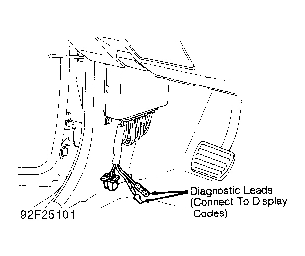
Fig. 1: Isuzu Rodeo LS 1994 - Component Locations - Locating Diagnostic Leads
Fig. 2: Isuzu Rodeo LS 1994 - Component Locations - Reading Trouble Codes (Typical)

Isuzu Rodeo LS 1994 - CLEARING CODES
- After repairs are performed, clear ECM memory of all stored codes. Ensure ignition is off. To clear codes, remove fuse No. 3 from instrument panel fuse block, or remove 60-amp MAIN fuse located in engine compartment fuse block.
- Trouble codes can also be cleared by disconnecting negative battery cable. However, other memory functions (clock, radio, etc.) will need to be reset.
Isuzu Rodeo LS 1994 - CODE CHARTS
NOTE: To identify ECM connector terminals, see ECM TERMINAL IDENTIFICATION chart. To test ECM power supply, go to TEST NO. 1 chart.
NOTE: Wire colors may vary. Check wiring diagrams for proper application.
Isuzu Rodeo LS 1994 ECM 26-PIN TERMINAL IDENTIFICATION
Pin No. Wire Color Main Connection 1 Light/Green Red Power 2 Black/Green Injector Ground 3 Black/Yellow DLC (ALDL) 4 Blue/Yellow Idle Input (WOT Switch) 5 Green/Black AC Input 6 0 Not Used 7 Green/Blue CKP Sensor Signal 8 Light Green/Yellow Pressure Regulator Control 9 Brown/Yellow Air Management VSV 10 Light Green EGR Duty Solenoid 11 0 Not Used 12 White/Black Injector No. 2 13 Violet/White Injector No. 1 14 Light Green/Black Power 15 0 Not Used 16 0 Not Used 17 0 Trans Input 18 0 Not Used 19 0 Not Used 20 White CKP Sensor Reference 21 White/Green EGR VSV 22 Green MIL 23 Green/White EVAP VSV 24 White/Blue Injector No. 4 25 White/Red Injector No. 3 26 Black/Green Injector Ground
NOTE: Wire colors may vary. Check wiring diagrams for proper application.
Isuzu Rodeo LS 1994 ECM 22-PIN TERMINAL IDENTIFICATION
Pin No. Wire Color Main Connection 1 Blue Power Signal 2 Black/Red Ground (Power, Ignition) 3 Green/Orange MAP Sensor Reference 4 Red/White Power (Backup) 5 White/Green Vehicle Speed Sensor 6 Shield Oxygen Sensor 7 Black/White ECT Sensor Ground 8 Brown/White ECT Sensor Input 9 Blue/White MAP Sensor Input 10 0 Not Used 11 Black Ground (Power) 12 Not Used Not Used 13 Black/Red Ground (Power, Ignition) 14 Red Airflow Sensor (Power) 15 Green/Red WOT Input (WOT Switch) 16 Yellow/Black Starter Switch 17 Shield Airflow Sensor 18 Blue/Red MAP Sensor Ground 19 Violet Airflow Sensor Ground 20 Red Oxygen Sensor Input 21 White Airflow Sensor Input 22 Black Ground (Power)
CAUTION: Perform all voltage measurements with ECM harness connector installed. Use a high-impedance voltmeter (10,000 ohm minimum). Verify battery voltage is greater than 11 volts.
Isuzu Rodeo LS 1994 - ECM LOCATION
ECM is located near left kick panel.
Isuzu Rodeo LS 1994 - TROUBLE CODE DEFINITION
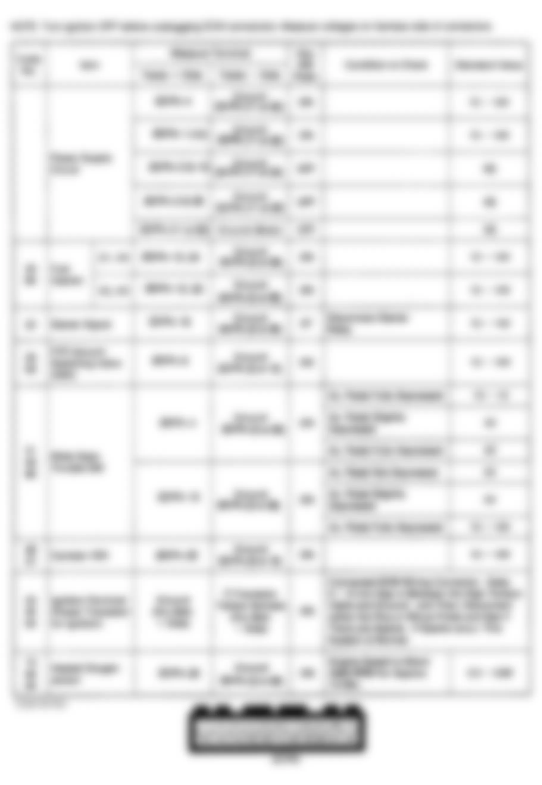
Isuzu Rodeo LS 1994 TROUBLE CODE IDENTIFICATION
Code System Affected Probable Cause 12 System Normal System Normal 13 Oxygen Sensor Circuit Sensor/Circuit, ECM 14 Coolant Temperature Sensor (Shorted) Temperature Sensor/ Circuit, ECM 15 Coolant Temperature Sensor (Open) Temperature Sensor/ Circuit, ECM 21 Throttle Valve Switch (Idle & Full Throttle) Switch/Circuit, ECM 22 Starter Signal Circuit, ECM 23 Power Transistor (Shorted) Transistor/Circuit, ECM 25 Pressure Regulator VSV VSV/Circuit, ECM 26 Canister Purge VSV VSV/Circuit, ECM 27 Canister Purge VSV VSV/Circuit, ECM 32 EGR System EGR Valve, Backpressure Transducer, Vacuum Switching Valve 33 Fuel Injector Circuit (Open or Grounded) Wiring, Dropping Resistor, ECM 34 MAP Sensor Sensor/Circuit, ECM 35 Power Transistor (Open) Transistor/Circuit, ECM 41 Crankshaft Position Sensor Sensor/Circuit, ECM 43 Throttle Valve Switch (Idle Position) Switch/Circuit, ECM 44 Oxygen Sensor (Lean/Rich) Injectors, Fuel Pressure, Airflow Sensor, Oxygen SensorCircuit, Coolant Temperature Sensor, ECM 45 Oxygen Sensor (Lean/Rich) Injectors, Fuel Pressure, Airflow Sensor, Oxygen SensorCircuit, Coolant Temperature Sensor, ECM 51 Faulty ECM ROM Defective ECM 52 Faulty ECM RAM Defective ECM 53 Pressure Regulator VSV VSV/Circuit, ECM 54 Power Transistor (Grounded) Transistor/Circuit, ECM 61 Airflow Sensor Sensor/Circuit, ECM 62 Airflow Sensor Sensor/Circuit, ECM 63 Vehicle Speed Sensor Sensor/Circuit, ECM 64 Fuel Injector Circuit (ECM Transistor) Wiring Harness, ECM 65 Throttle Valve Switch (Full Throttle) Switch/Circuit, ECM
Isuzu Rodeo LS 1994 - DIAGNOSTIC CIRCUIT CHECK
Fig. 4: Isuzu Rodeo LS 1994 - Component Locations - Diagnostic Circuit Check
Isuzu Rodeo LS 1994 - TEST NO. 1 - CHECKING ECM POWER SUPPLY Circuit Confirmation
- Disconnect ECM harness connectors.
- Turn ignition switch to ON position.
- Ensure battery voltage is present at terminals No. 1, 14 and 4.
- Ensure continuity exists between terminals No. 11 and 22.
Isuzu Rodeo LS 1994 - Inspection & Correction
- If battery voltage is not present at terminals No. 1, 14 and 4, check main relay, starter switch, fuses, fusible link wires and related circuits. Correct or replace parts as necessary.
- If continuity does not exist between terminals No. 11 and 22, correct or replace grounding cable.
- Reconnect ECM harness connectors.
Fig. 5: Isuzu Rodeo LS 1994 - Component Locations - Test No. 1 - ECM Power Supply
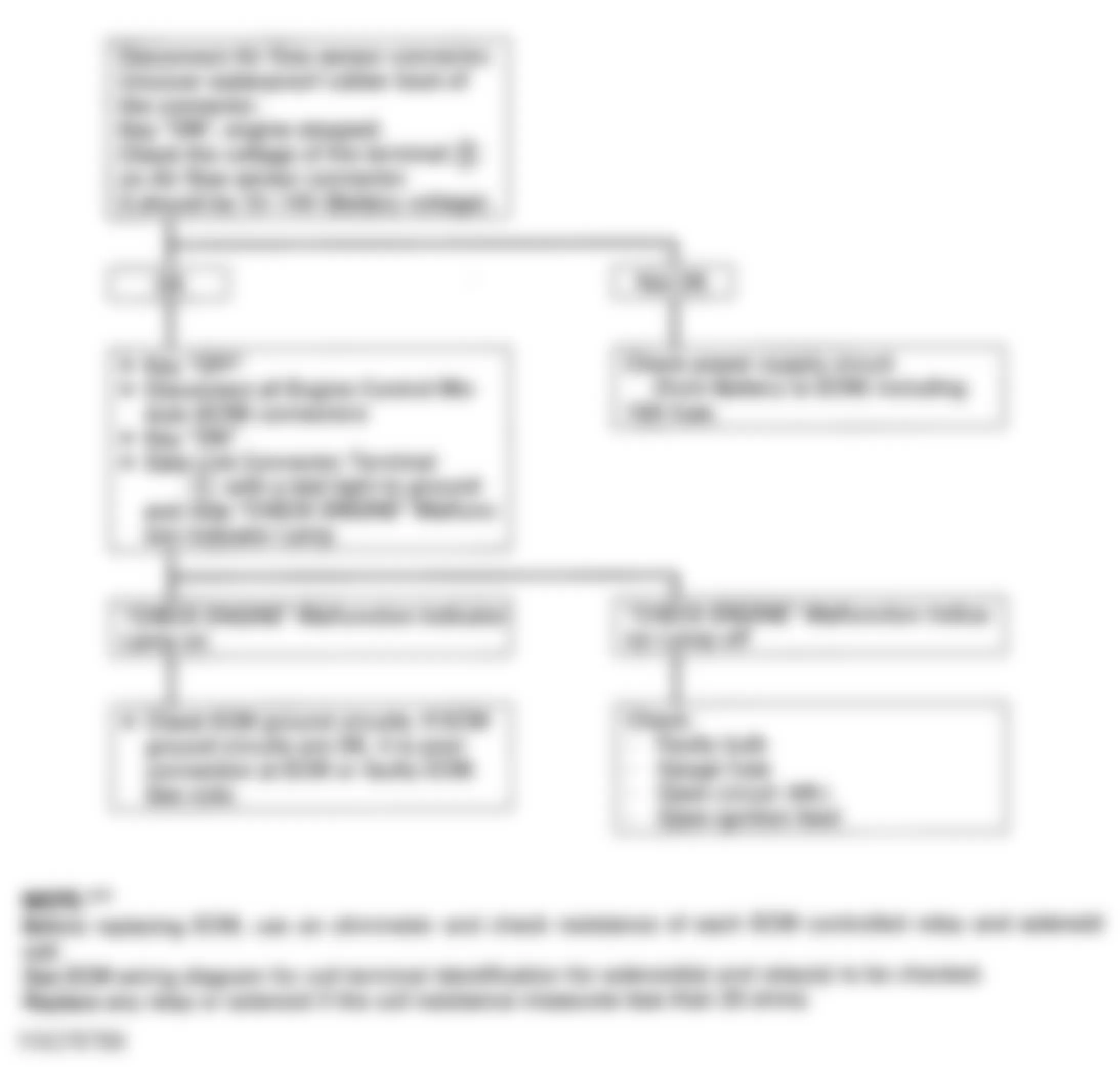
Isuzu Rodeo LS 1994 - TEST NO. 2 - CHECK ENGINE LIGHT INOPERATIVE
NOTE: Before replacing ECM, check resistance of ECM-controlled relay and solenoid coils. See appropriate wiring diagram in WIRING DIAGRAMS article for coil terminal identification of solenoids and relays. Replace any solenoid or relay with less than 20 ohms resistance.
Fig. 6: Isuzu Rodeo LS 1994 - Component Locations - Airflow Sensor Connector

Fig. 7: Isuzu Rodeo LS 1994 - Component Locations - Data Link Connector

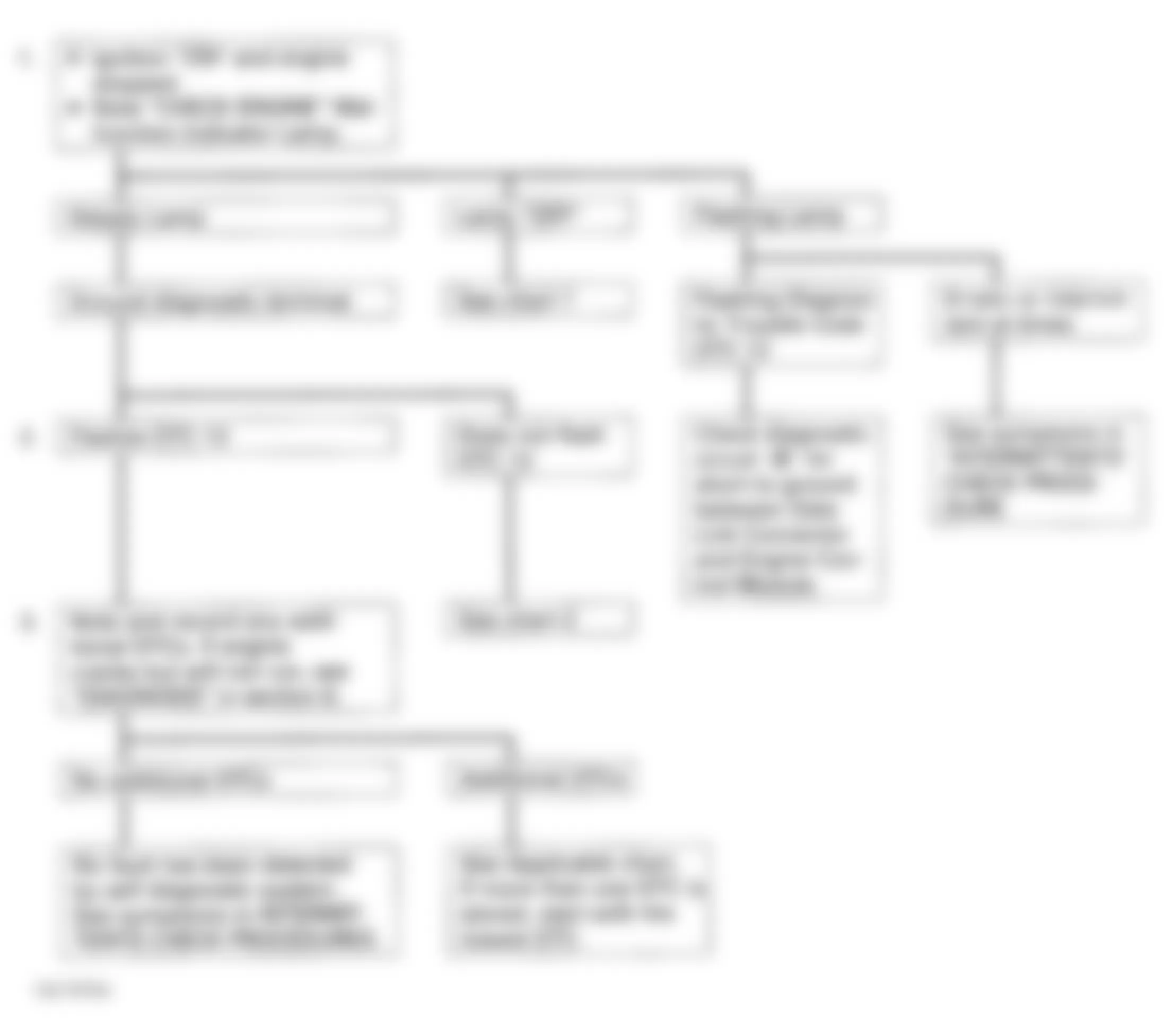
Fig. 8: Isuzu Rodeo LS 1994 - Component Locations - Test No. 2 - Diagnostic Flowchart
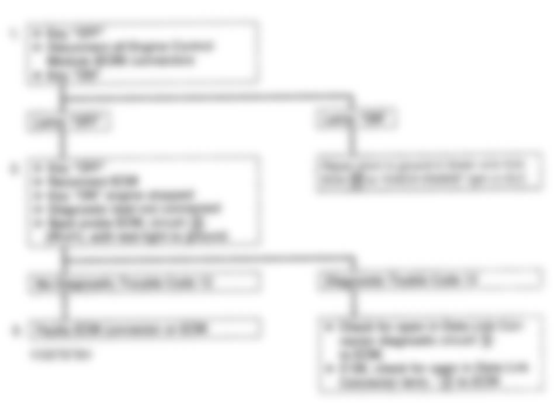
Isuzu Rodeo LS 1994 - TEST NO. 3 - WILL NOT FLASH CODE 12
NOTE: See appropriate wiring diagram in WIRING DIAGRAMS article for terminal and connector identification.
Fig. 9: Isuzu Rodeo LS 1994 - Component Locations - Airflow Sensor Connector

Fig. 10: Isuzu Rodeo LS 1994 - Component Locations - Data Link Connector

Fig. 11: Isuzu Rodeo LS 1994 - Component Locations - Test No. 3 - Diagnostic Flowchart
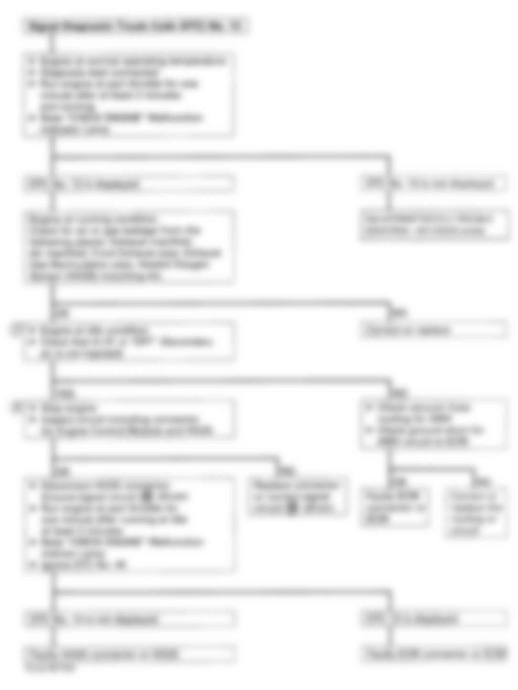
Isuzu Rodeo LS 1994 - CODE 12 - SYSTEM NORMAL
This DTC No. 12 is always displayed with the key "ON" and the engine not running and it only means that the engine is not running. This DTC No. 12 is not stored in memory.
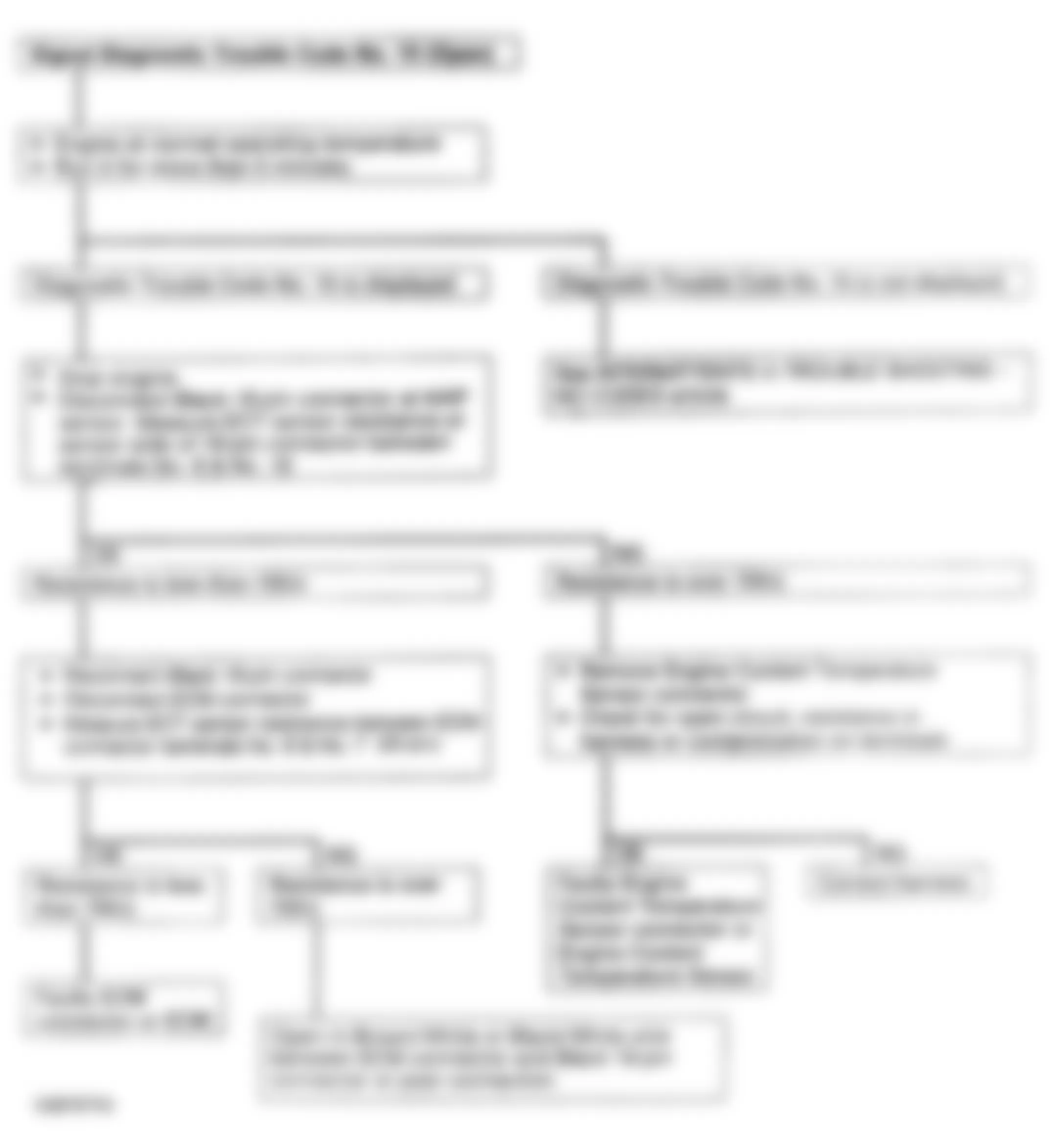
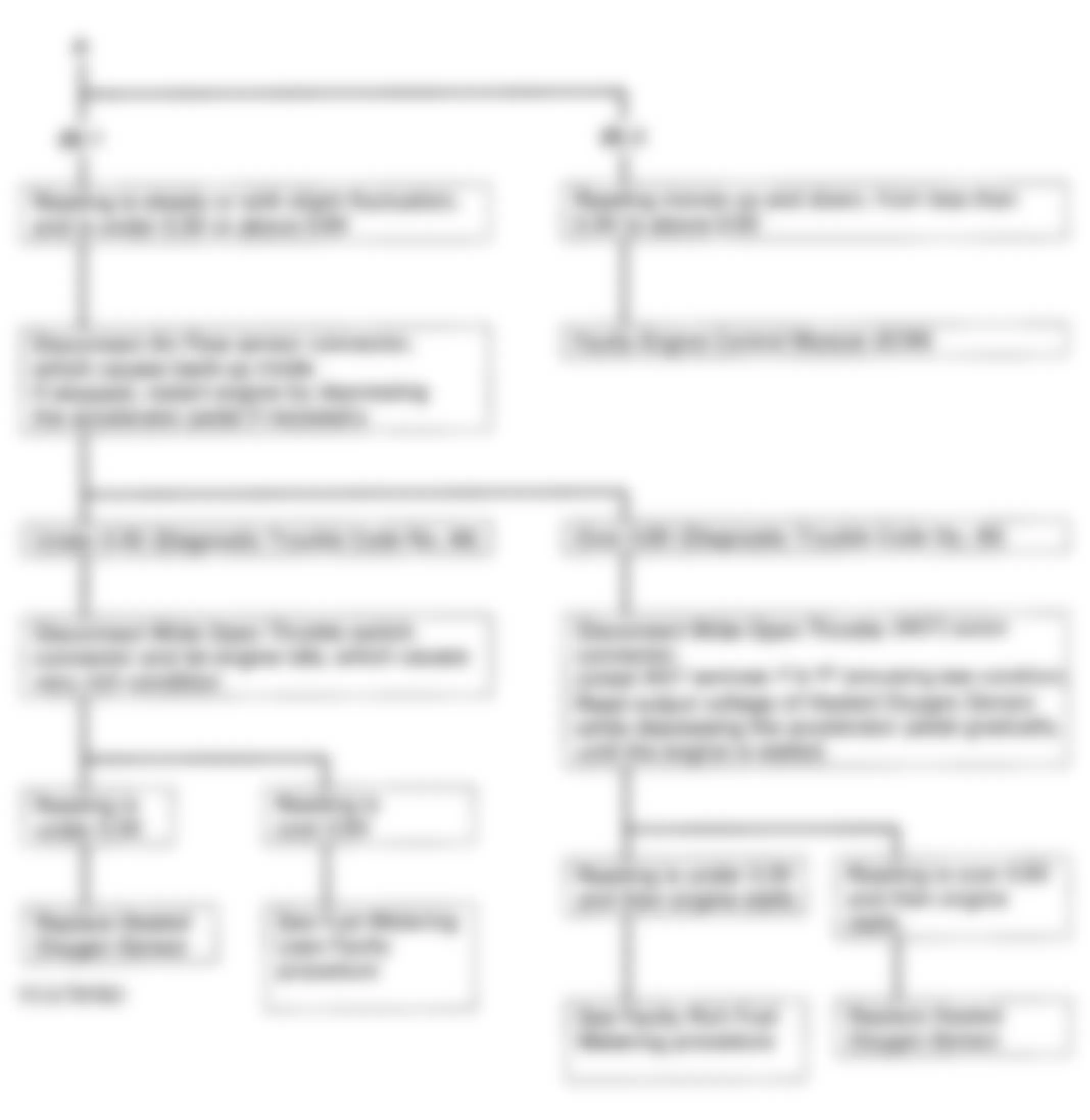
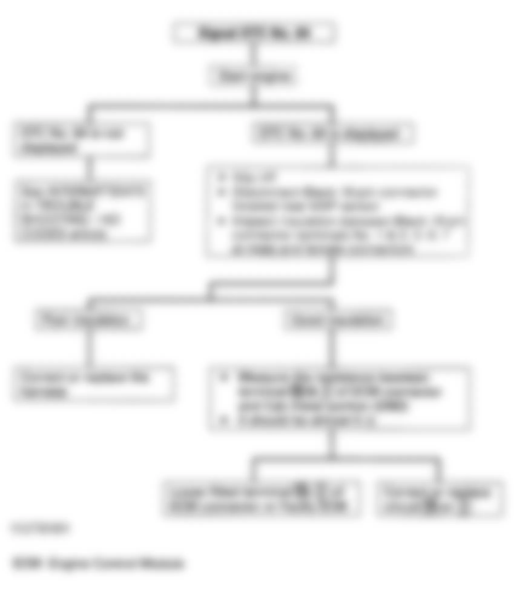
Isuzu Rodeo LS 1994 - CODE 13 - HEATED OXYGEN SENSOR CIRCUIT
NOTE: See appropriate wiring diagram in WIRING DIAGRAMS article for terminal and connector identification.
NOTE: Test numbers refer to numbers on diagnostic chart.
- This step checks AIR system operation:
- Idle engine at normal operating temperature.
- Stop engine.
- Disconnect AIR hose at check valve and plug check valve.
- Restart engine and idle, immediately check direction of airflow.
- This step tests continuity of oxygen sensor circuit (Red wire) between ECM 22-pin connector terminal No. 20 and oxygen sensor.
Fig. 12: Isuzu Rodeo LS 1994 - Component Locations - Code 13 - Diagnostic Flowchart
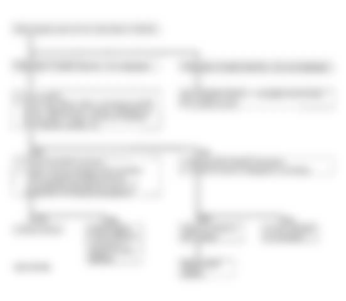
Isuzu Rodeo LS 1994 - CODE 14 - SHORTED - ENGINE COOLANT TEMPERATURE SENSOR
NOTE: See appropriate wiring diagram in WIRING DIAGRAMS article for ECM terminal and connector identification.
Fig. 13: Isuzu Rodeo LS 1994 - Component Locations - ECT Sensor Side Of Black 16-Pin Connector
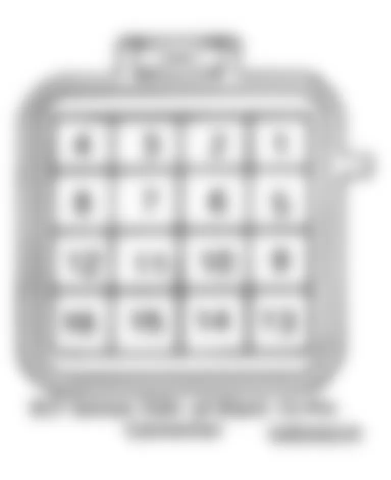
Fig. 14: Isuzu Rodeo LS 1994 - Component Locations - Code 14 - Diagnostic Flowchart
Isuzu Rodeo LS 1994 - CODE 15 - OPEN - ENGINE COOLANT TEMPERATURE SENSOR
NOTE: See appropriate wiring diagram in WIRING DIAGRAMS article for ECM terminal and connector identification.
Fig. 15: Isuzu Rodeo LS 1994 - Component Locations - ECT Sensor Side Of Black 16-Pin Connector

Fig. 16: Isuzu Rodeo LS 1994 - Component Locations - Code 15 - Diagnostic Flowchart
Isuzu Rodeo LS 1994 - CODE 21 - THROTTLE VALVE SWITCH (IDLE & FULL THROTTLE)
NOTE: See appropriate wiring diagram in WIRING DIAGRAMS article for ECM terminal and connector identification.
Fig. 17: Isuzu Rodeo LS 1994 - Component Locations - Code 21 - Throttle Valve Switch

Fig. 18: Isuzu Rodeo LS 1994 - Component Locations - Code 21 - Diagnostic Flowchart (1 Of 2)
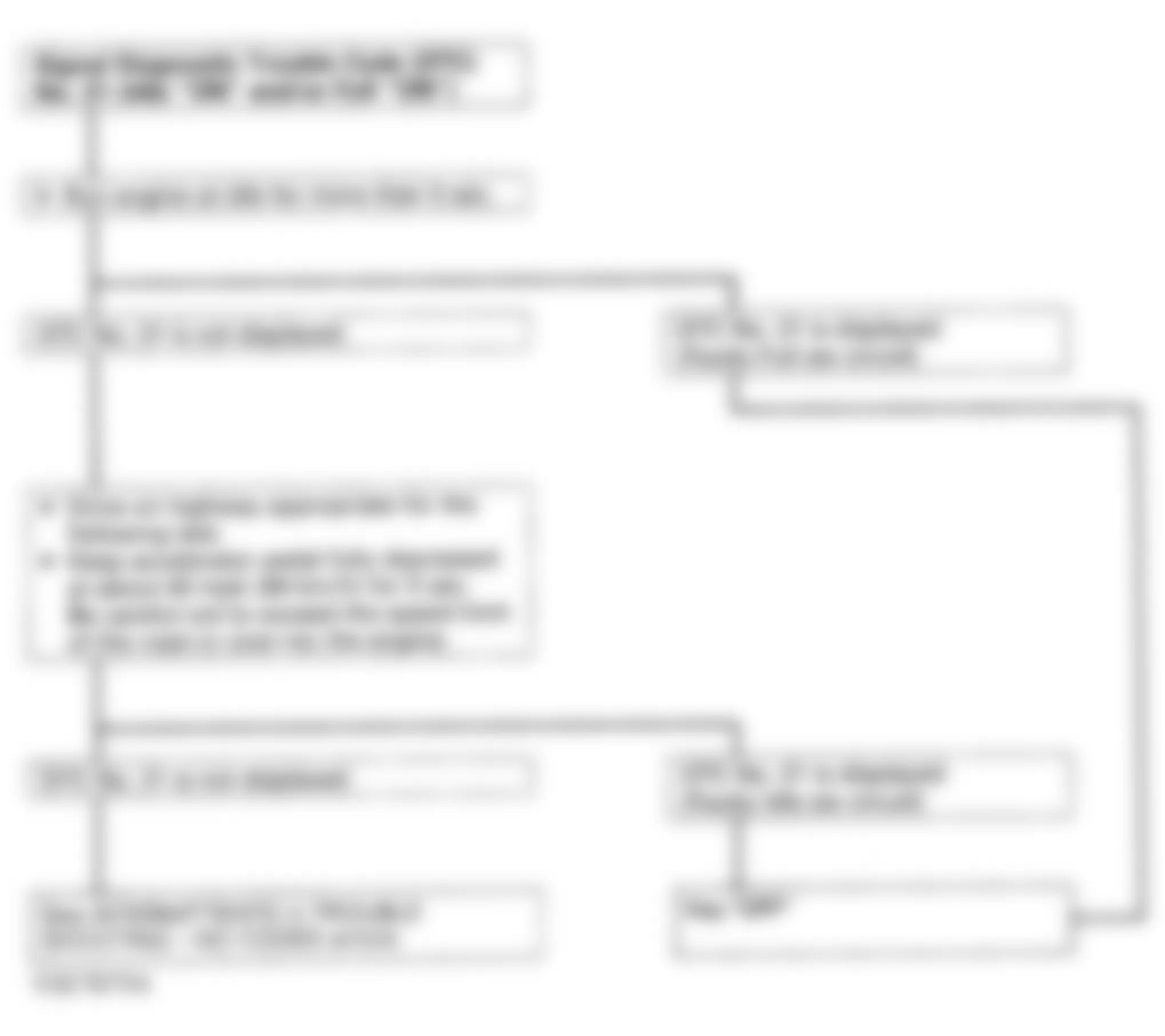
Fig. 19: Isuzu Rodeo LS 1994 - Component Locations - Code 21 - Diagnostic Flowchart (2 Of 2)

Isuzu Rodeo LS 1994 WOT SWITCH CONTINUITY
Accelerator Pedal Continuity I-P (Ohms) Continuity P-F (Ohms) Not Depressed 0 Infinity Slightly Depressed Infinity Infinity Fully Depressed Infinity 0
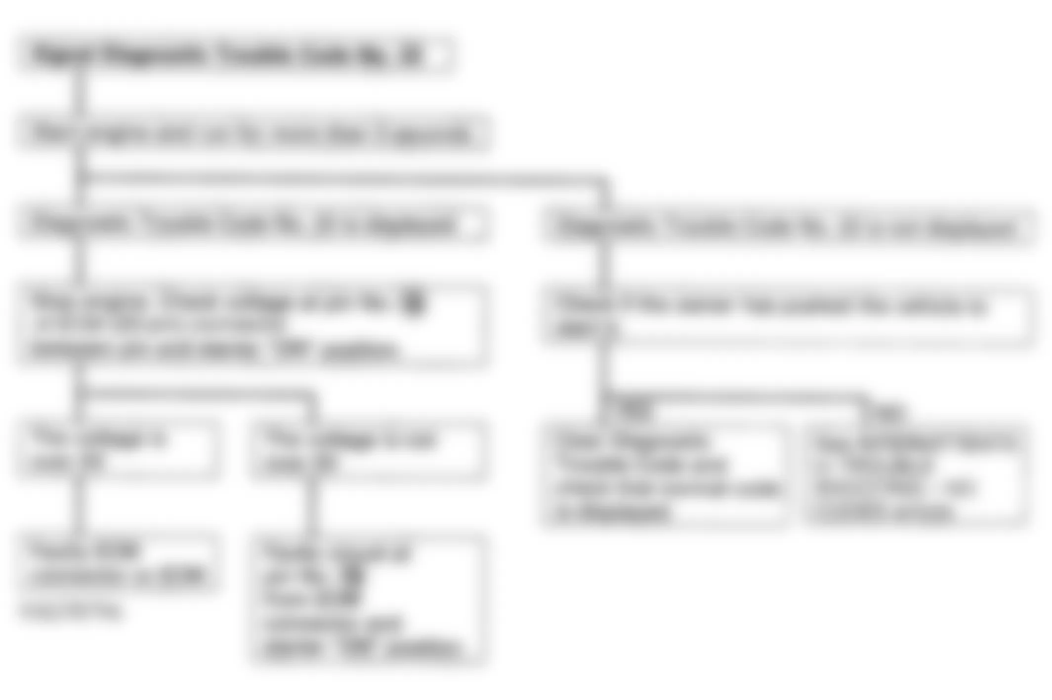
Isuzu Rodeo LS 1994 - CODE 22 - STARTER SIGNAL
NOTE: See appropriate wiring diagram in WIRING DIAGRAMS article for terminal and connector identification.
Fig. 20: Isuzu Rodeo LS 1994 - Component Locations - Code 22 - Diagnostic Flowchart
Isuzu Rodeo LS 1994 - CODE 23, 35 & 54 - POWER TRANSISTOR CIRCUIT
NOTE: See appropriate wiring diagram in WIRING DIAGRAMS article for terminal and connector identification.
NOTE: Test numbers refer to numbers on diagnostic chart.
- This step checks continuity of power transistor power circuit. Check continuity of ground at ECM terminal No. 13.
- Inspecting power transistor:
- Disconnect coil wire at distributor.
- Attach Spark Tester (J-125) or equivalent to free end of coil wire.
- Remove power transistor from bottom of intake manifold, and disconnect harness connector.
- Connect a 2-wire jumper lead between power transistor connector and power transistor. In one wire of jumper lead install a 1.5-volt dry cell battery with negative side of battery facing power transistor.
- Ground power transistor to frame and turn ignition on.
- Disconnect and reconnect jumper lead at power transistor connector. Verify spark exists at spark tester. If spark is not present, replace power transistor.
Fig. 21: Isuzu Rodeo LS 1994 - Component Locations - Code 23, 35, 54 - Diagnostic Flowchart
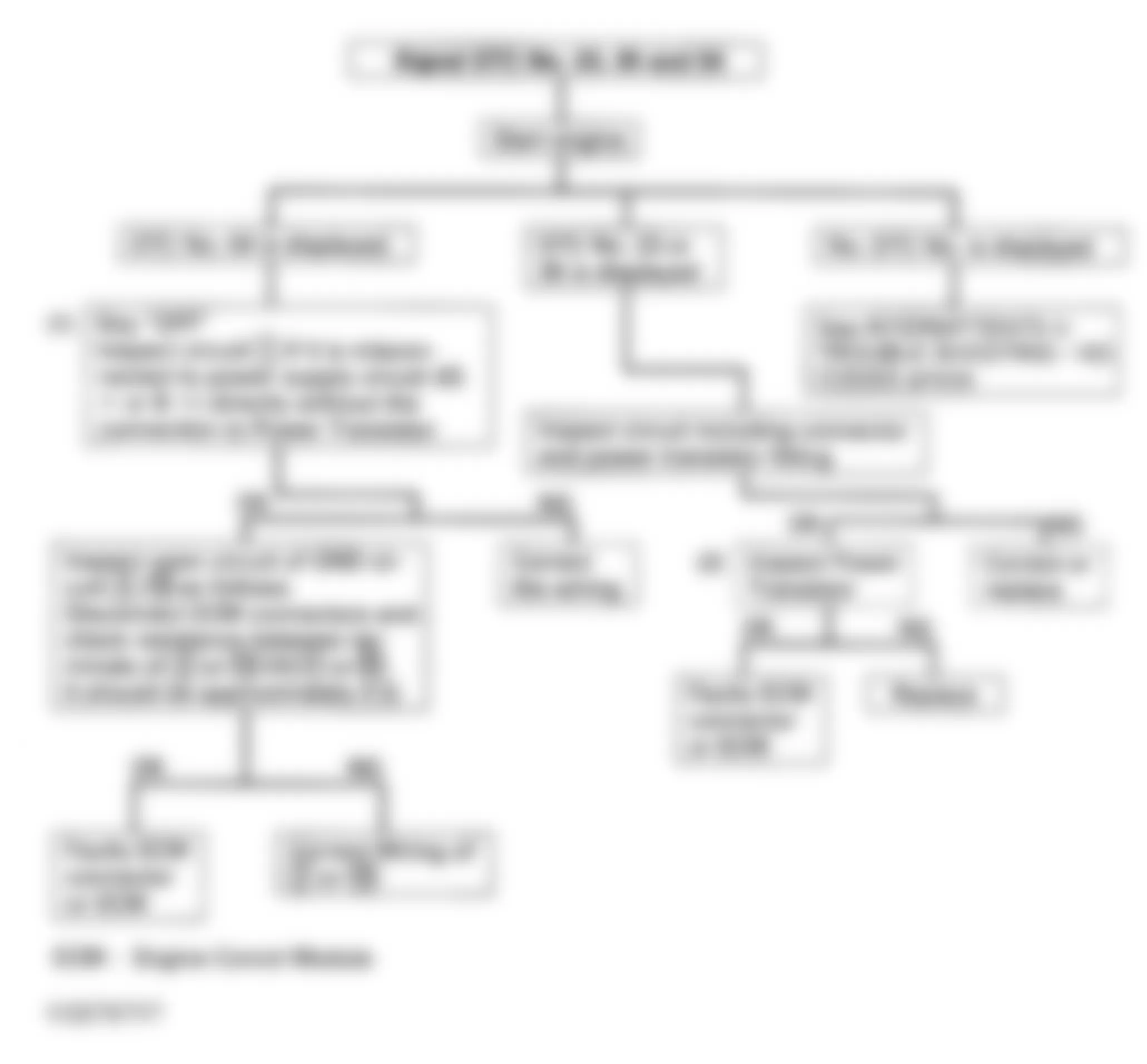
Isuzu Rodeo LS 1994 - CODE 25 & 53 - FUEL PRESSURE REGULATOR VSV
NOTE: See appropriate wiring diagram in WIRING DIAGRAMS article for terminal and connector identification.
NOTE: Test number refers to number on diagnostic chart.
- Test resistance between Light Green/Black wire and Light Green/Yellow wire at VSV connector.
Fig. 22: Isuzu Rodeo LS 1994 - Component Locations - Code 25, 53 - Diagnostic Flowchart (1 Of 2)
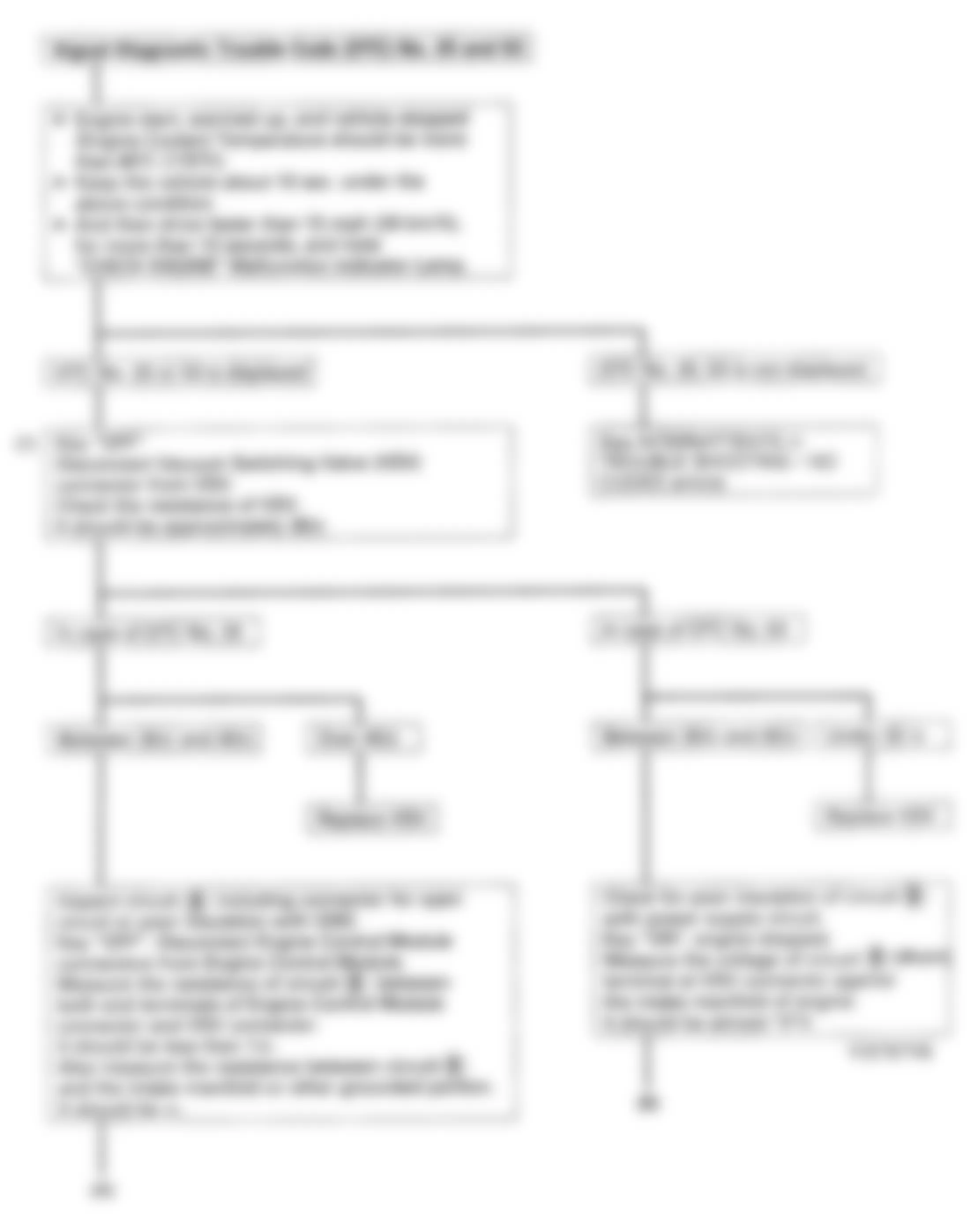
Fig. 23: Isuzu Rodeo LS 1994 - Component Locations - Code 25,53 - Diagnostic Flowchart (2 Of 2)
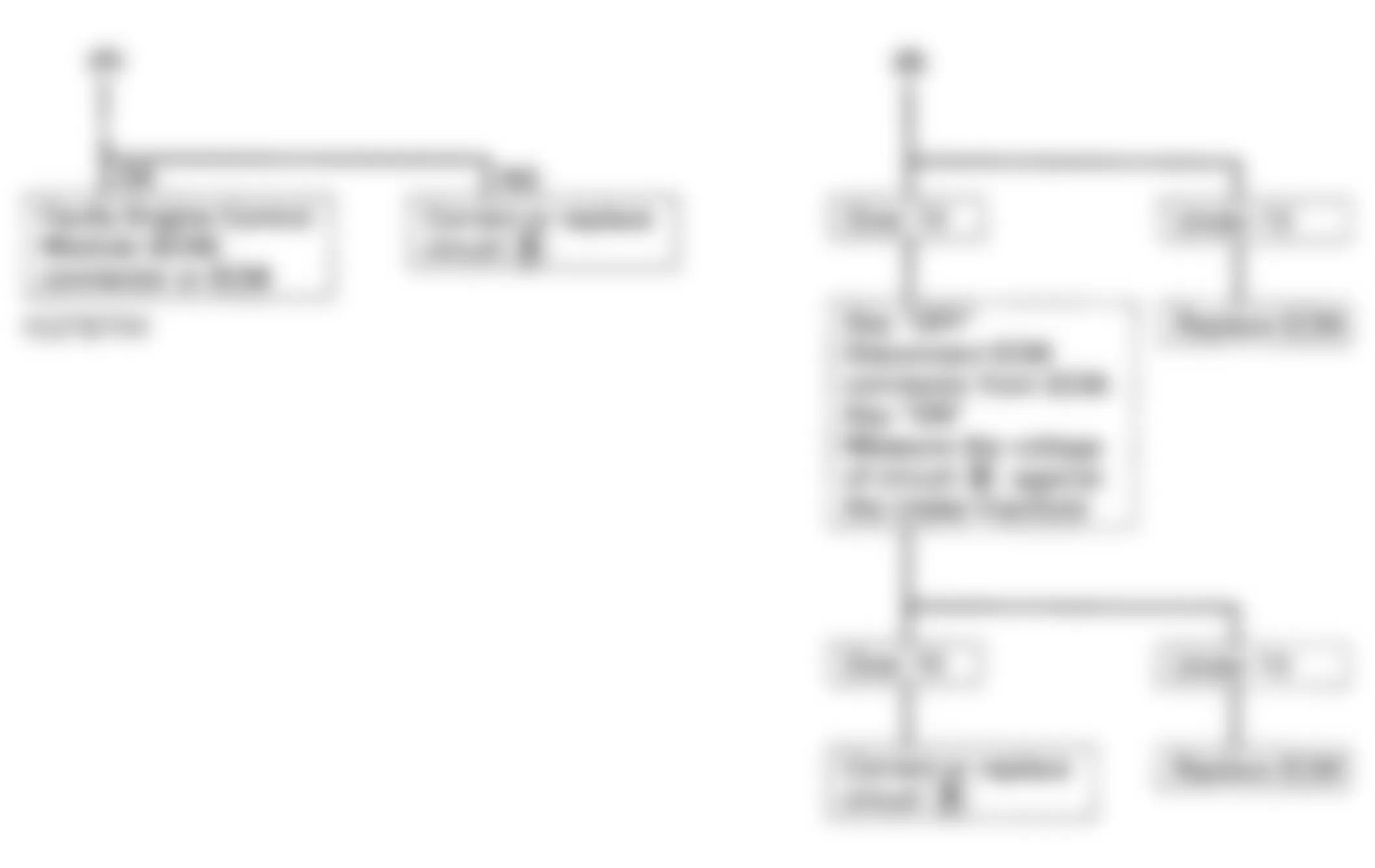
Isuzu Rodeo LS 1994 - CODE 26 & 27 - CANISTER PURGE VSV
NOTE: See appropriate wiring diagram in WIRING DIAGRAMS article for terminal and connector identification.
NOTE: Test number refers to number on diagnostic chart.
- Test resistance between Light Green/Black wire and Green/White wire at VSV connector.
Fig. 24: Isuzu Rodeo LS 1994 - Component Locations - Code 26, 27 - Diagnostic Flowchart (1 Of 2)
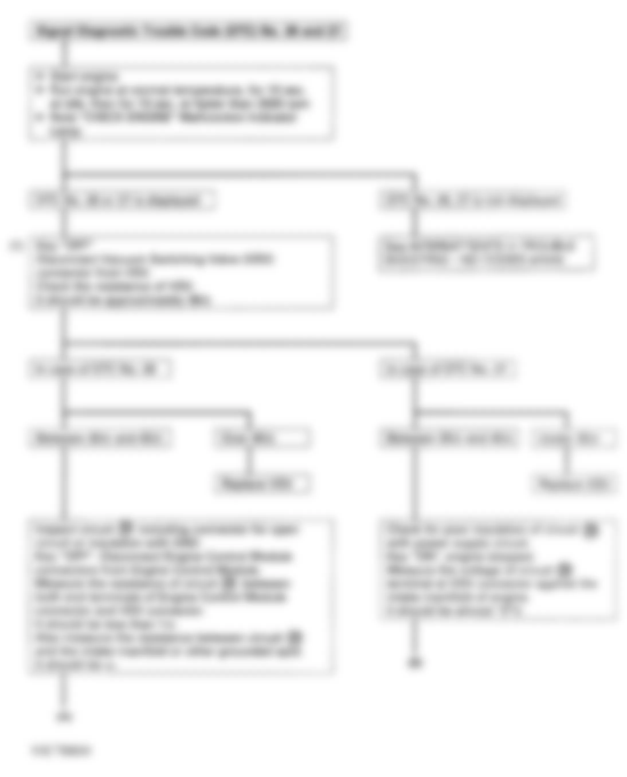
Fig. 25: Isuzu Rodeo LS 1994 - Component Locations - Code 26, 27 - Diagnostic Flowchart (2 Of 2)
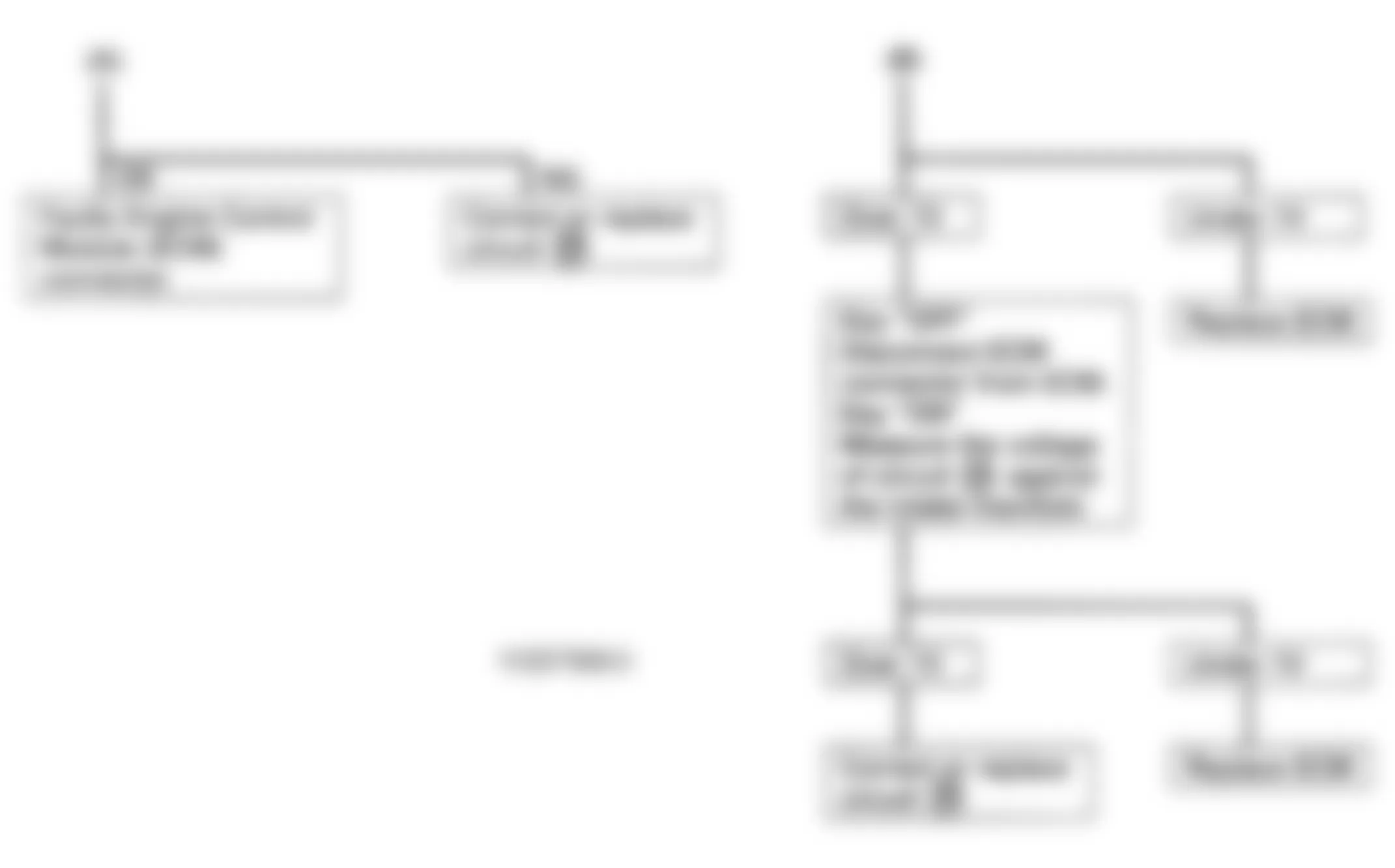
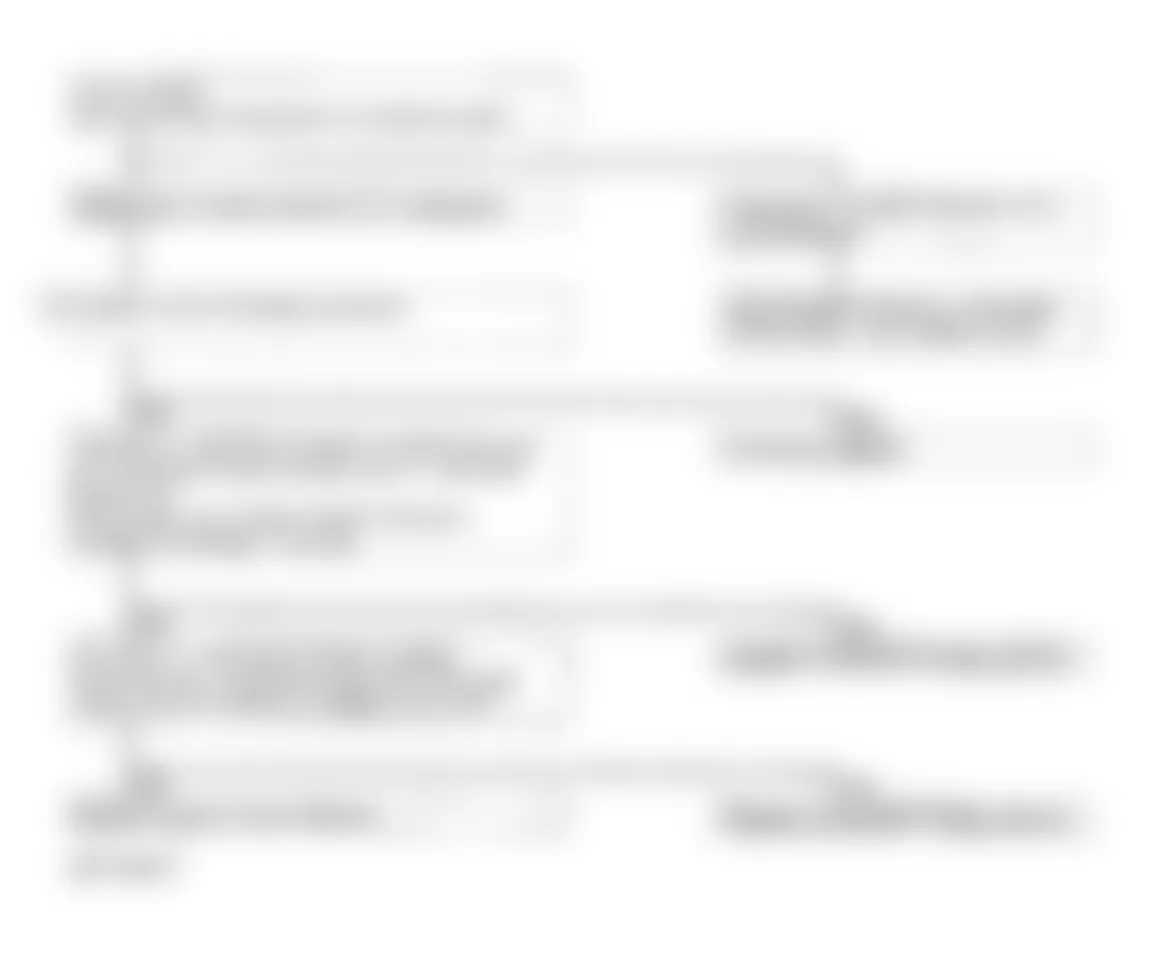
Isuzu Rodeo LS 1994 - CODE 32 - EGR SYSTEM MALFUNCTION
NOTE: See appropriate wiring diagram in WIRING DIAGRAMS article for terminal and connector identification.
NOTE: Test numbers refer to numbers on diagnostic chart.
- Specified Reappearance Pattern
- Run engine at idle and normal operating temperature.
- Keep vehicle at idle for more than 10 minutes at stop.
- Drive vehicle at 10 MPH. Accelerate to more than 30 MPH.
- After 10-30 seconds, decelerate to complete stop.
- Repeat pattern several times.
- This step checks EGR operation by re-applying signal vacuum.
Fig. 26: Isuzu Rodeo LS 1994 - Component Locations - Code 32 - Specified Reappearance Pattern
Fig. 27: Isuzu Rodeo LS 1994 - Component Locations - Code 32 - Diagnostic Flowchart (1 Of 3)
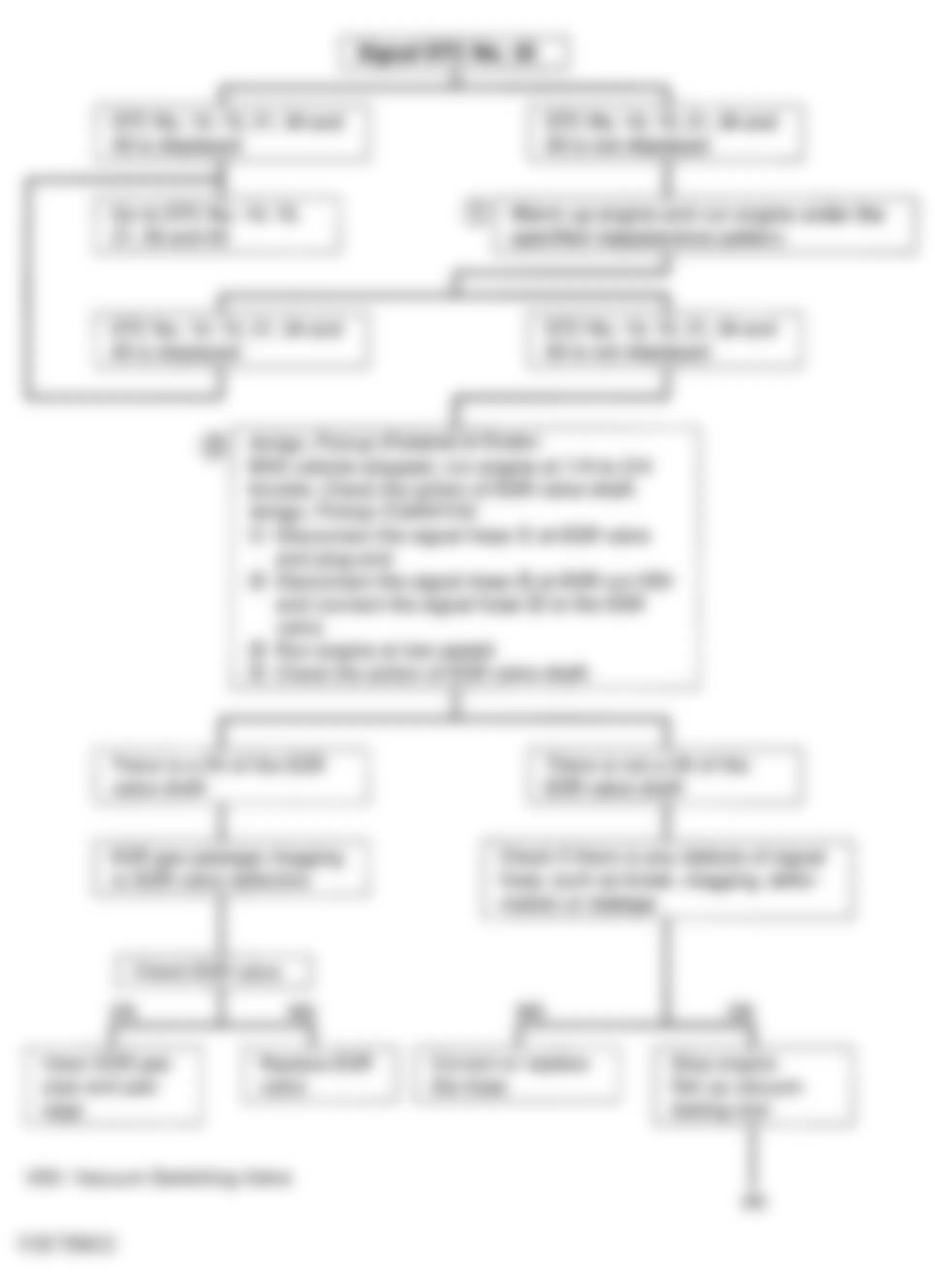
Fig. 28: Isuzu Rodeo LS 1994 - Component Locations - Code 32 - Diagnostic Flowchart (2 Of 3)
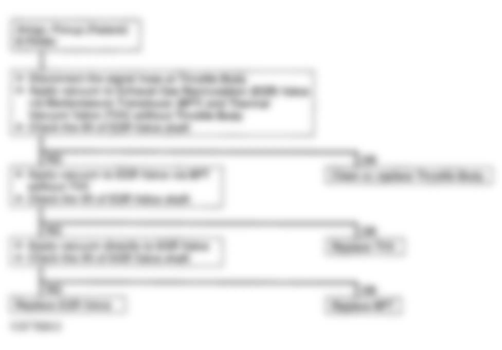
Fig. 29: Isuzu Rodeo LS 1994 - Component Locations - Code 32 - Diagnostic Flowchart (3 Of 3)
Isuzu Rodeo LS 1994 - CODE 33 - FUEL INJECTOR - CIRCUIT (OPEN OR GROUNDED)
NOTE: See appropriate wiring diagram in WIRING DIAGRAMS article for terminal and connector identification.
Fig. 30: Isuzu Rodeo LS 1994 - Component Locations - Code 33 - Diagnostic Flowchart
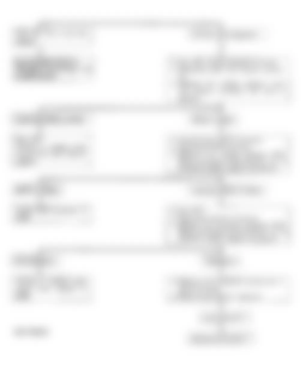
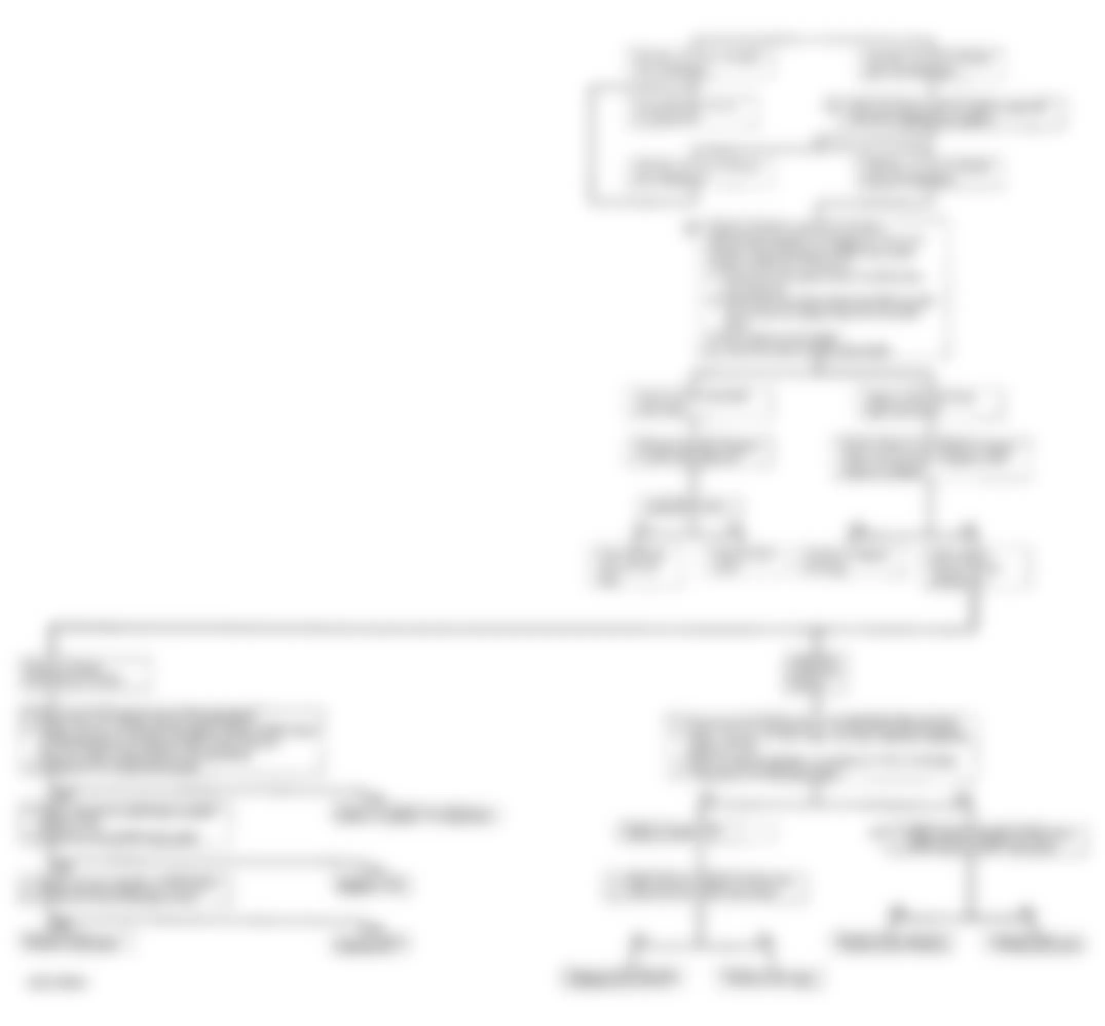
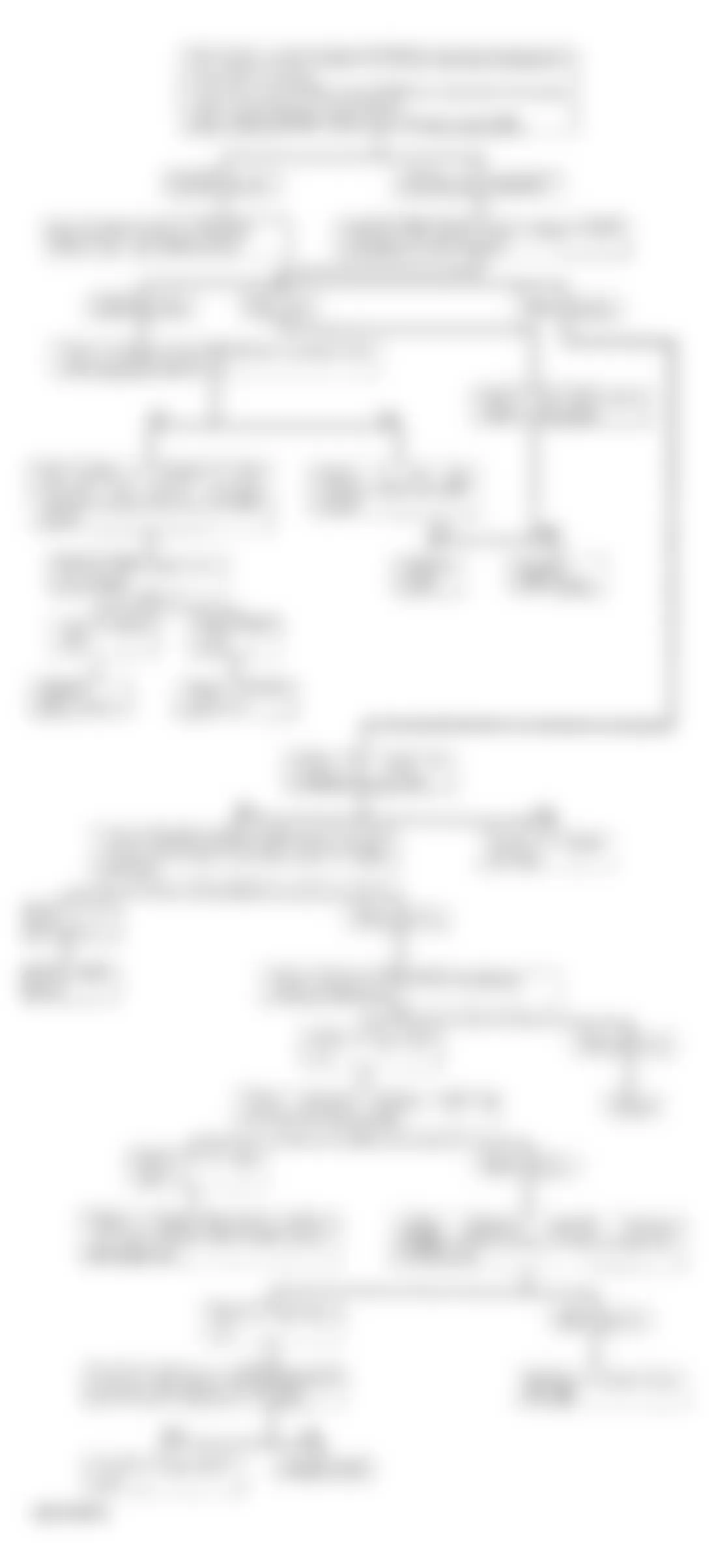
Isuzu Rodeo LS 1994 - CODE 34 - MAP SENSOR
NOTE: See appropriate wiring diagram in WIRING DIAGRAMS article for terminal and connector identification.
Fig. 31: Isuzu Rodeo LS 1994 - Component Locations - Code 34 - Diagnostic Flowchart (1 Of 2)
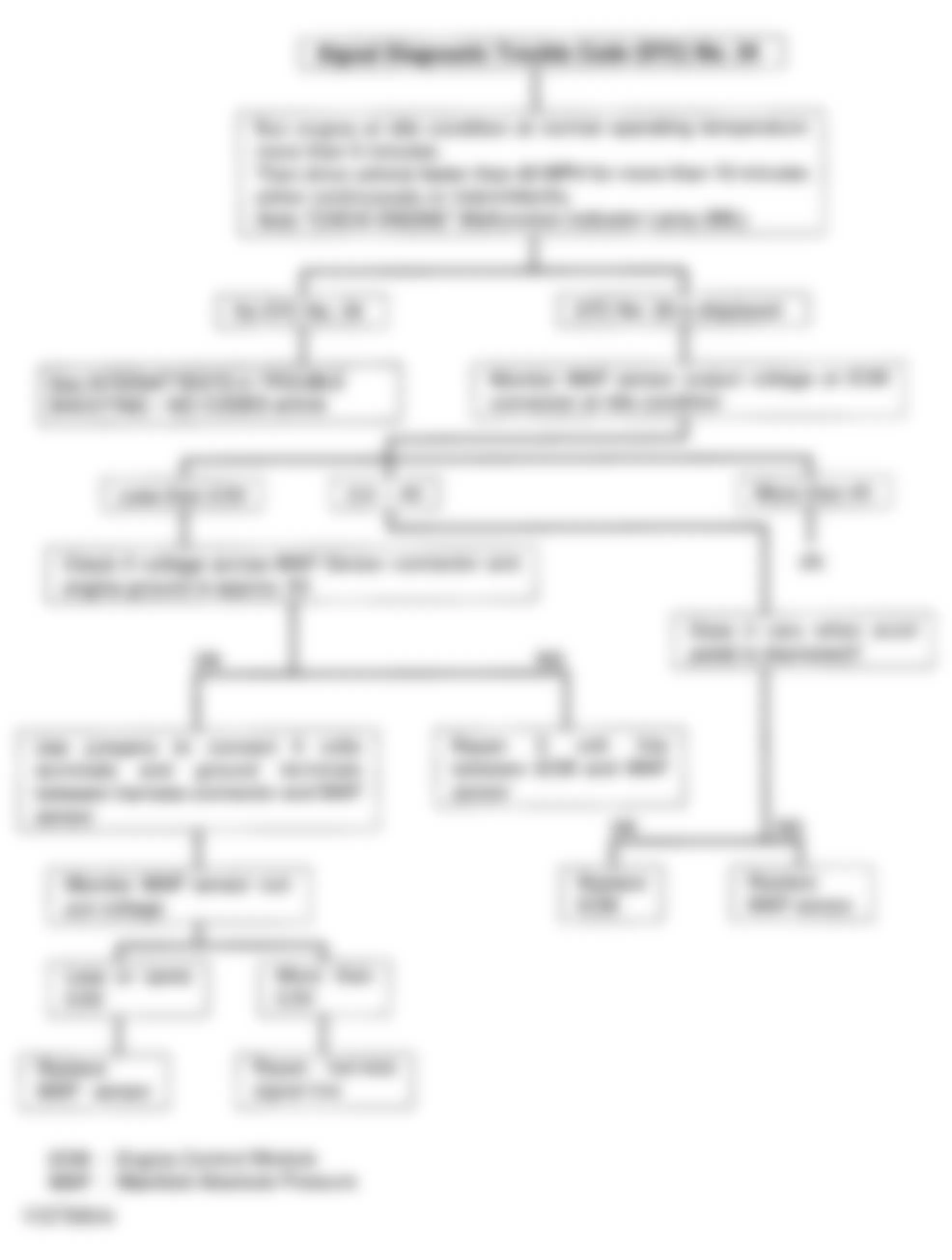
Fig. 32: Isuzu Rodeo LS 1994 - Component Locations - Code 34 - Diagnostic Flowchart (2 Of 2)
Isuzu Rodeo LS 1994 - CODE 41 - CRANKSHAFT POSITION SENSOR SIGNAL
NOTE: See appropriate wiring diagram in WIRING DIAGRAMS article for terminal and connector identification.
NOTE: Test number refers to number on diagnostic chart.
- Inspecting Crankshaft Position (CKP) sensor circuit:
- Disconnect CKP sensor and ECM connectors.
- Turn ignition on.
- Measure CKP sensor voltage and resistance values. See CKP SENSOR SPECIFICATIONS table.
- If values are not within specification, repair or replace appropriate harness or connector.
- Reconnect CKP and ECM connectors.
Isuzu Rodeo LS 1994 CKP SENSOR SPECIFICATIONS
Between Terminals (1) Resistance Voltage 20 & Black/White 0 N/A 7 & Green/Yellow 0 N/A Green/Black & Ground 0 10-14 Black & Ground 0 N/A
(1) Circuit numbers refer to ECM terminal numbers, and wire colors refer to CKP sensor wire colors at connector.
Fig. 33: Isuzu Rodeo LS 1994 - Component Locations - Code 41 - Diagnostic Flowchart
Isuzu Rodeo LS 1994 - CODE 43 &65 - THROTTLE VALVE SWITCH
NOTE: See appropriate wiring diagram in WIRING DIAGRAMS article for ECM terminal and connector identification.
Fig. 34: Isuzu Rodeo LS 1994 - Component Locations - Code 43, 65 - Throttle Valve Switch

Fig. 35: Isuzu Rodeo LS 1994 - Component Locations - Code 43, 65 - Diagnostic Flowchart (1 Of 2)
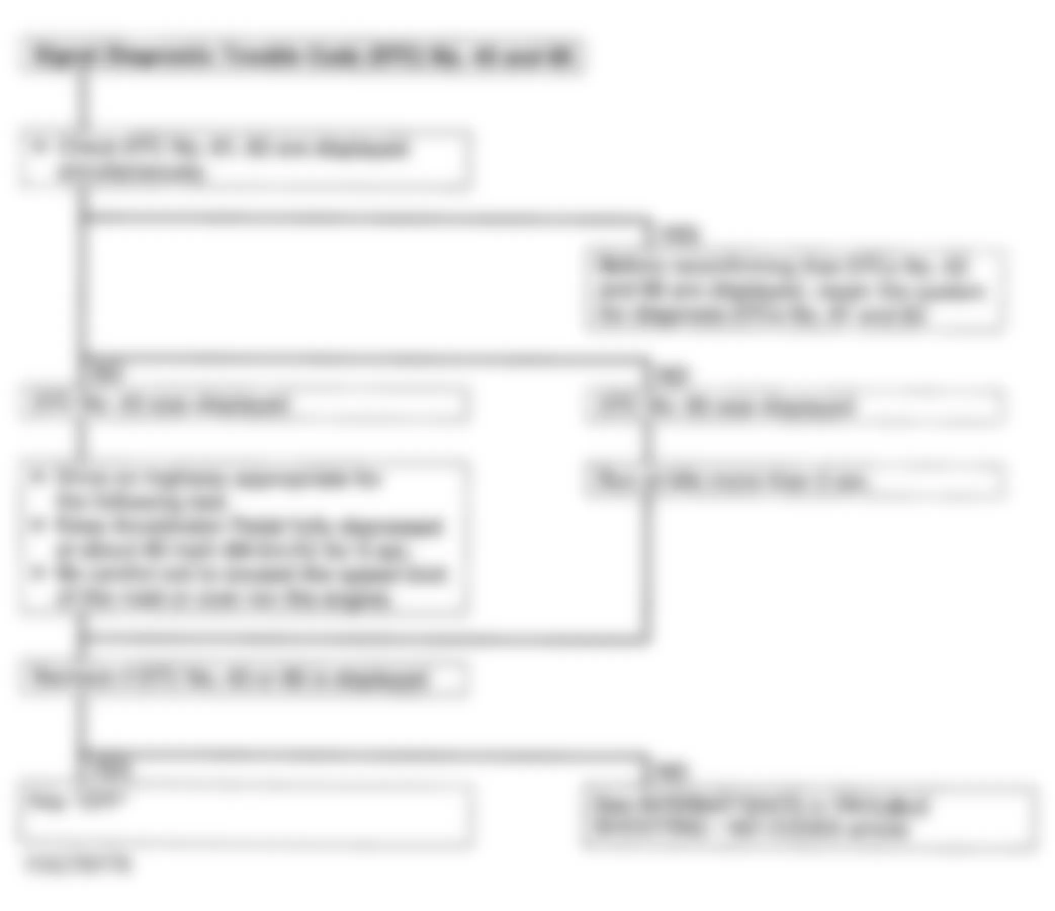
Fig. 36: Isuzu Rodeo LS 1994 - Component Locations - Code 43, 65 - Diagnostic Flowchart (2 Of 2)
Isuzu Rodeo LS 1994 WOT SWITCH CONTINUITY
Accelerator Pedal Continuity I-P (Ohms) Continuity P-F (Ohms) Not Depressed 0 Infinity Slightly Depressed Infinity Infinity Fully Depressed Infinity 0
Isuzu Rodeo LS 1994 - CODE 44 & 45 - OXYGEN SENSOR-LEAN/RICH FUEL MIXTURE
NOTE: See appropriate wiring diagram in WIRING DIAGRAMS article for terminal and connector identification.
NOTE: Test numbers refer to numbers on diagnostic chart.
- Measure voltage at oxygen sensor connector.
- Jumper wire allows voltage measurement of circuit.
Fig. 37: Isuzu Rodeo LS 1994 - Component Locations - Code 44, 45 - Diagnostic Flowchart (1 Of 2)
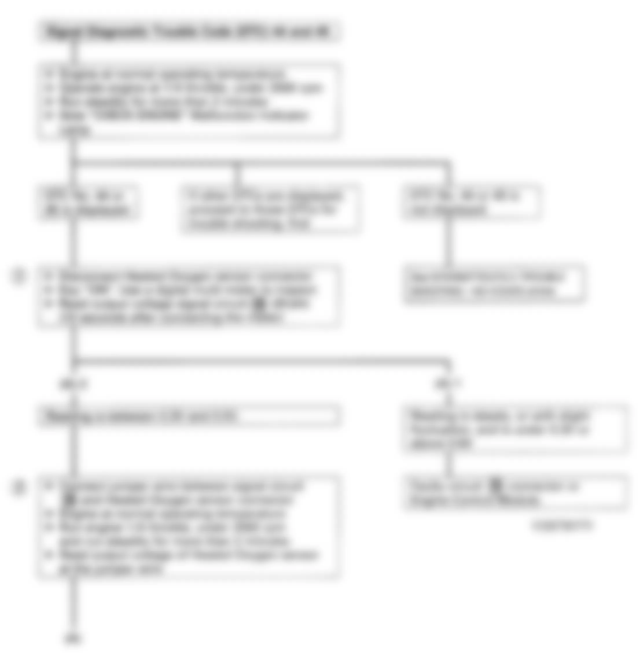
Fig. 38: Isuzu Rodeo LS 1994 - Component Locations - Code 44-, 45 - Diagnostic Flowchart (2 Of 2)
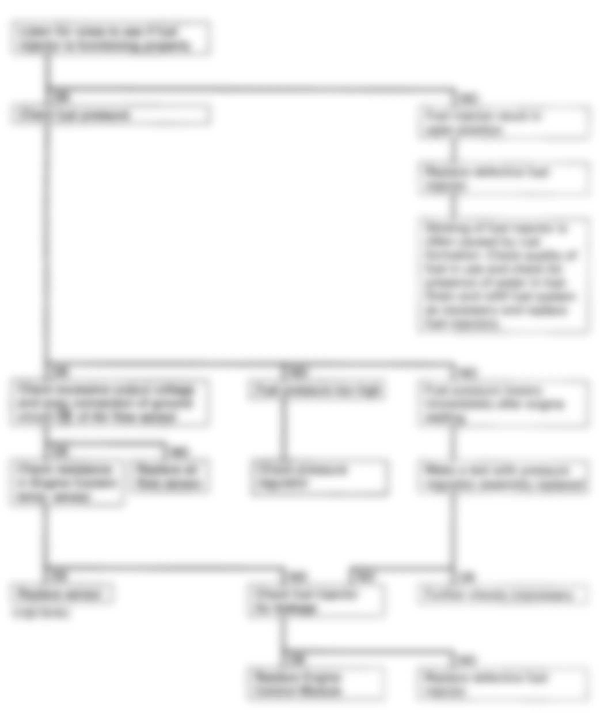
Isuzu Rodeo LS 1994 - FUEL METERING RICH FAULTY INSPECTION PROCEDURE
NOTE: See appropriate wiring diagram in WIRING DIAGRAMS article for terminal and connector identification.
Fig. 39: Isuzu Rodeo LS 1994 - Component Locations - Fuel Metering Rich - Diagnostic Flowchart
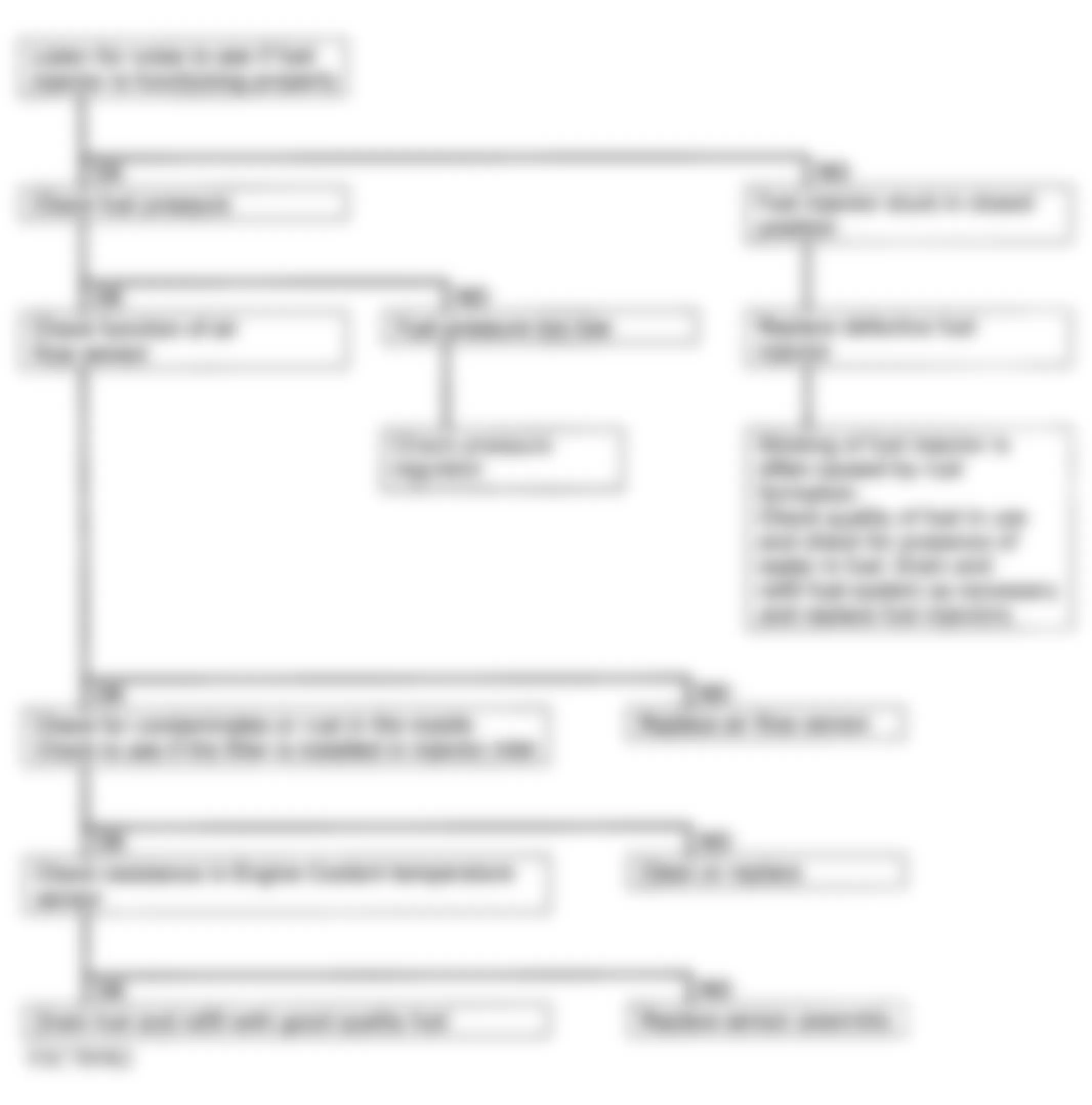
Isuzu Rodeo LS 1994 - FUEL METERING LEAN FAULTY INSPECTION PROCEDURE
NOTE: See appropriate wiring diagram in WIRING DIAGRAMS article for terminal and connector identification.
Fig. 40: Isuzu Rodeo LS 1994 - Component Locations - Fuel Metering Lean - Diagnostic Flowchart
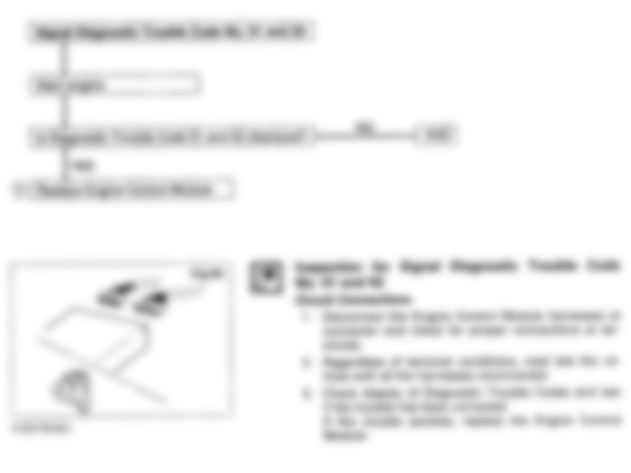
Isuzu Rodeo LS 1994 - CODE 51 & 52 - FAULTY ECM RAM/ROM
NOTE: See appropriate wiring diagram in WIRING DIAGRAMS article for terminal and connector identification.
NOTE: Test number refers to number on diagnostic chart.
- Before replacing ECM, check circuit connections:
- Disconnect ECM harness connectors. Inspect all terminals and repair as necessary.
- Reconnect ECM harness connectors, and road test vehicle.
- Check for codes. If condition persists or code reappears, replace ECM.
Fig. 41: Isuzu Rodeo LS 1994 - Component Locations - Code 51, 52 - Diagnostic Flowchart
Isuzu Rodeo LS 1994 - CODE 61 & 62 - AIRFLOW SENSOR SIGNAL
NOTE: See appropriate wiring diagram in WIRING DIAGRAMS article for terminal and connector identification.
Fig. 42: Isuzu Rodeo LS 1994 - Component Locations - Code 61, 62 - Diagnostic Flowchart (1 Of 2)
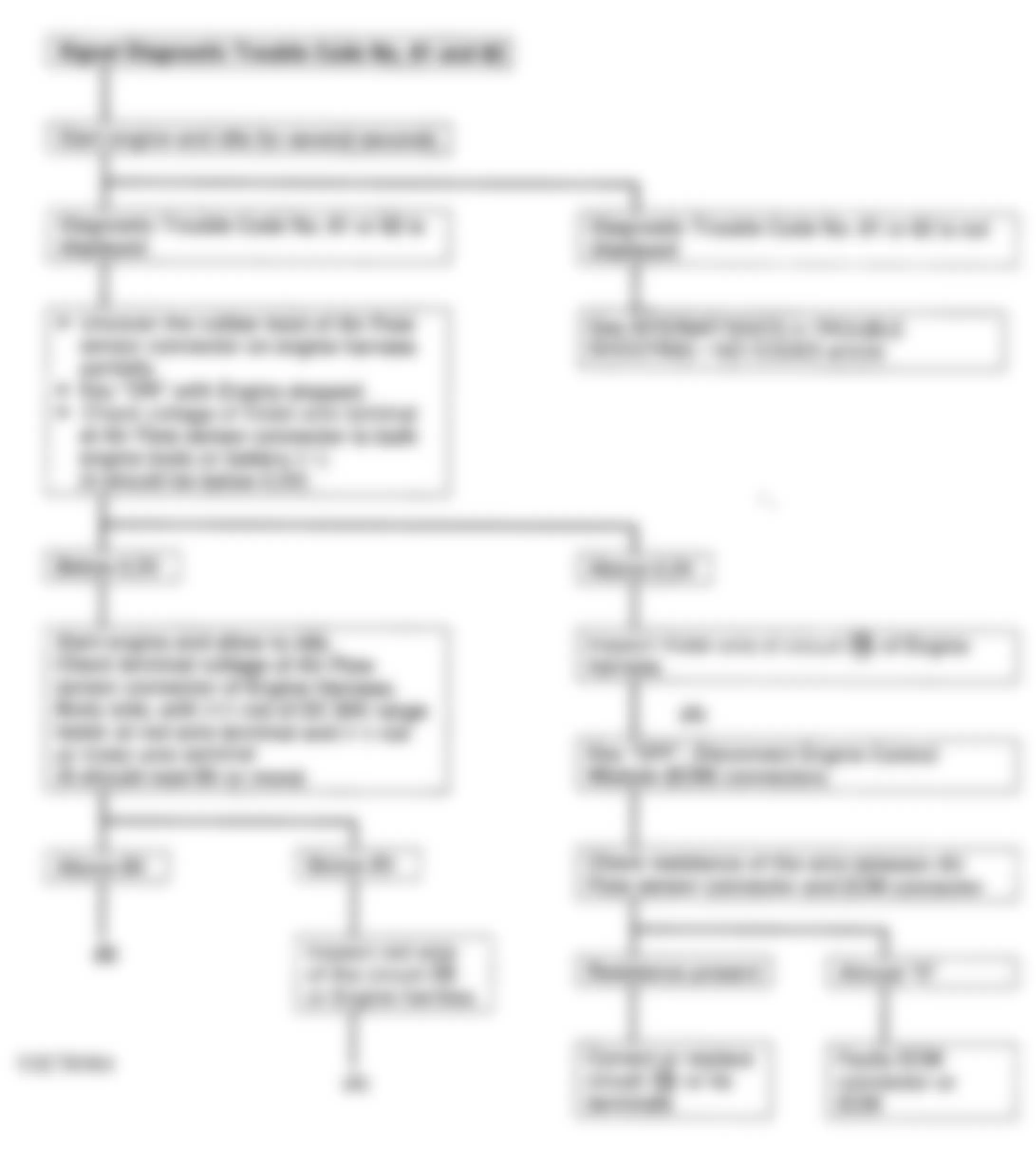
Fig. 43: Isuzu Rodeo LS 1994 - Component Locations - Code 61, 62 - Diagnostic Flowchart (2 Of 2)
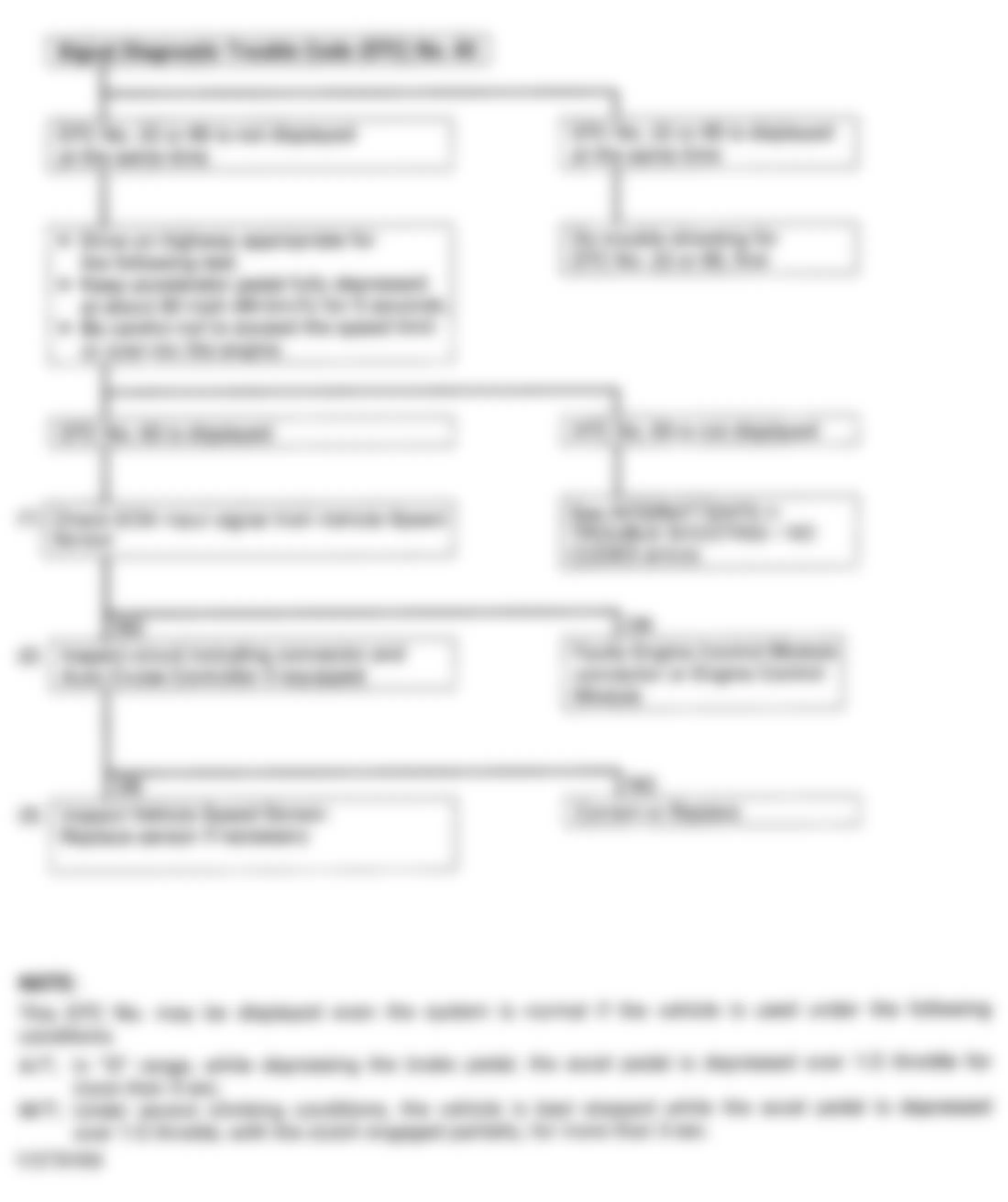
Isuzu Rodeo LS 1994 - CODE 63 - VEHICLE SPEED SENSOR SIGNAL
NOTE: See appropriate wiring diagram in WIRING DIAGRAMS article for terminal and connector identification.
Code 63 can be set, without a system failure, under following conditions:
- Auto. Trans. In Drive position, with brake pedal depressed and accelerator pedal depressed more than halfway for more than 3 seconds.
- Manual Trans. Under severe climbing conditions, with vehicle stationary, accelerator pedal depressed more than halfway for more than 3 seconds, and clutch partially engaged.
NOTE: Test numbers refer to numbers on diagnostic chart.
- Check for continuity between ECM 22-pin connector terminal No. 5 (White/Green wire) and ground. Disconnect speedometer cable at transmission. Tester should pulsate between open and continuity as speedometer cable is rotated slowly.
NOTE: Instrument cluster has two 12-pin connectors. Ensure appropriate wire color is tested. - Ensure continuity exists on White/Green wire between ECM 22-pin connector terminal No. 5 and instrument cluster 12-pin connector terminal No. 9. Ensure continuity exists on Black/White wire between instrument cluster 12-pin connector terminal No. 9 and ground.
- Remove instrument cluster assembly. Check continuity between terminals No. 1 and 2. Tester should pulsate between open and continuity as speedometer inner shaft is rotated slowly.
Fig. 44: Isuzu Rodeo LS 1994 - Component Locations - Instrument Cluster Connections
Fig. 45: Isuzu Rodeo LS 1994 - Component Locations - Code 63 - Diagnostic Flowchart
Isuzu Rodeo LS 1994 - CODE 64 - FUEL INJECTOR CIRCUIT (ECM TRANSISTOR)
NOTE: See appropriate wiring diagram in WIRING DIAGRAMS article for ECM terminal and circuit identification.
Fig. 46: Isuzu Rodeo LS 1994 - Component Locations - ECT Sensor Side Of Black 16-Pin Connector

Fig. 47: Isuzu Rodeo LS 1994 - Component Locations - Code 64 - Diagnostic Flowchart
Isuzu Rodeo LS 1994 - SUMMARY
If no hard fault codes (or only pass codes) are present, driveability symptoms exist or intermittent codes exist, proceed to TESTS W/O CODES article for diagnosis by symptom (i.e., ROUGH IDLE, NO START, etc.) or intermittent diagnostic procedures.