
Isuzu Rodeo LS 1996 - 1996 ENGINE PERFORMANCE Self-Diagnostics - Rodeo - 2.6L 4-Cyl.
Isuzu Rodeo LS 1996 - INTRODUCTION
NOTE: The CHECK ENGINE light is now referred to as Malfunction Indicator Light (MIL). The MIL is displayed in instrument cluster as CHECK ENGINE.
If no faults were found while performing steps in BASIC TESTING - 2.6L 4-CYL article, proceed with self-diagnostics. If no Diagnostic Trouble Codes (DTCs) are present after entering self-diagnostics, proceed to TESTS W/O CODES - 2.6L 4-CYL article for diagnosis by symptoms.
Isuzu Rodeo LS 1996 - SYSTEM DESCRIPTION
The PCM monitors engine operation. It also contains a self-diagnostic system which stores Diagnostic Trouble Codes (DTCs) and compares them to On-Board Diagnostics Generation II (OBD-II) standards. Federal law mandates this type of diagnostic system for all vehicles by 1996.
The goal of OBD-II regulation is to provide vehicle with an on-board diagnostic system which is capable of continuously monitoring the efficiency of emission control systems, and to improve diagnosis and repair when system failures occur.
The Federal Test Procedure (FTP) sets maximum allowable emission standards. A Malfunction Indicator Light (MIL) must illuminate if a system or component either fails or deteriorates to a point where the vehicles emissions could rise above 1 1/2 times FTP standards.
DTCs may only be retrieved using an On-Board Diagnostic (OBD-II) scan tester.
Isuzu Rodeo LS 1996 - TRIP DETECTION LOGIC
Generation II data streams are prioritized. When two messages attempt to establish communications on a data line at the same time, only the message with higher priority will continue. A new segment of the software called the Diagnostic Executive coordinates the protocol for recording and displaying diagnostic procedures.
After engine has reached normal operating temperature, Diagnostic Executive checks if On Board Diagnostic Tests have been completed since last ignition cycle. It checks if tests have passed during current ignition cycle. Checks if fault identified by diagnostic tests is currently active. It also checks if fault identified has been active during current ignition cycle and what operating conditions were present at the time of failure.
Each test is separated in to four types:
- Type A - Turns the MIL on the first time an emission relate failure occurs. The MIL will FLASH at a rate of once per second to alert the operator of potentially damaging levels of misfire, such that could destroy the catalytic converter.
- Type B - Will only turn MIL on if an emission related condition occurs during two consecutive driving cycles. Conditions such as incorrect fuel trim will be stored in the Freez-Frame data until the fault is detected a second time. If the fault is not detected during three consecutive driving cycles, the MIL light will be turned off.
- Type C - This is a non-emission related type and will not activate the MIL. It will turn ON a Check Transmission service light, or other non MIL service reminder light.
- Type D - Is non-emission related, will not turn the MIL or service light, but will store DTCs of faults present.
Isuzu Rodeo LS 1996 - SELF-DIAGNOSTIC SYSTEM HARD FAILURES
Hard failures cause Malfunction Indicator Light (MIL) to glow and remain on until problem is repaired. If light comes on and remains on (light may flash) during vehicle operation, cause of malfunction must be determined using diagnostic (code) charts. See DIAGNOSTIC TROUBLE CODE DEFINITIONS. If a sensor fails, Powertrain Control Module (PCM) will use a substitute value in its calculations to continue engine operation. In this condition, commonly known as limp-in mode, vehicle runs but driveability will not be optimum.
Isuzu Rodeo LS 1996 - INTERMITTENT FAILURES
Intermittent failures may cause MIL to flicker or glow and go out after intermittent fault goes away. However, corresponding trouble code will be retained in PCM memory. If related fault does not reoccur within a certain time frame, related trouble code will be erased from PCM memory. Intermittent failures may be caused by a sensor, connector or wiring related problems. See INTERMITTENTS in appropriate TESTS W/O CODES - 2.6L 4-CYL article.
Isuzu Rodeo LS 1996 - FREEZE-FRAME DATA
According to the 1996 government regulations, engine operating conditions under witch the MIL is illuminated must be recorded. This record, called freeze frame data, is a snap shot of the driving conditions, that is recorded on the PCM freeze frame buffer and is constantly updated with the most current information.
Freeze frame data can only be overwritten with misfire or fuel trim malfunction data. The data can only be erased by clearing associated history DTCs.
Isuzu Rodeo LS 1996 - DATA LINK CONNECTOR LOCATION
Located at lower left side of instrument panel, behind a small cover.
Isuzu Rodeo LS 1996 - RETRIEVING CODES
NOTE: Codes can be retrieved using a scan tester. Trouble codes are referred to as DTCs.
- Code retrieval starts with diagnostic circuit check. See DIAGNOSTIC CIRCUIT CHECK. MIL will come on when ignition is on and engine is not running. When engine is started, MIL should go off. If light remains on while engine is running, a trouble code is present.
- If light does not come on with ignition on and engine off, inspect MIL circuit before continuing. If MIL fails to operate, see DIAGNOSTIC CIRCUIT CHECK.
- To retrieve codes, install scan tool. Select MIL dash lamp control and command the MIL OFF. Ensure MIL light is off and attempt to start engine. If vehicle does not start, go to vehicle NO-START tests.
Isuzu Rodeo LS 1996 - CLEARING CODES
- After repairs are performed, clear PCM memory of all stored codes. Ensure ignition is off. To clear codes, use diagnostic scan tool "clear DTCs" or "clear info" function. Follow instructions supplied by tool manufacturer, when clearing DTCs.
- Trouble codes can also be cleared by disconnecting any PCM power source or negative battery cable for at least 30 seconds. However, if disconnecting battery remember that other memory functions (clock, radio, etc.) will need to be reset.
Isuzu Rodeo LS 1996 - PCM REPROGRAM PROCEDURE
If PCM requires replacement PCM must be reprogrammed using a Tech I or other OBD II compatible scan tool.
Isuzu Rodeo LS 1996 - PCM LOCATION
PCM is located near left kick panel.
NOTE: If any DTCs not listed here are displayed by a scan tool, the scan tool data may be faulty. Notify the scan tool manufacturer of any DTCs displayed that are not included in the following table.
Isuzu Rodeo LS 1996 - DIAGNOSTIC TROUBLE CODE DEFINITIONS
Isuzu Rodeo LS 1996 DIAGNOSTIC TROUBLE CODE (DTC) IDENTIFICATION
DTC Type (1) Component/System Most Likely Cause P0106 A MAP Sensor Ckt Range/Performance Problem MAP Sensor P0107 A MAP Sensor Ckt Low Frequency Open/Short, MAP Sensor Or PCM P0108 A MAP Sensor Ckt High Frequency . Open, MAP Sensor Or PCM P0112 A IAT Sensor Ckt Low Frequency . Short, IAT Sensor Or PCM P0113 A IAT Sensor Ckt High Frequency . Open, IAT Sensor Or PCM P0117 A ECT Sensor Ckt Low Frequency Short, ECT Sensor Or PCM P0118 A ECT Sensor Ckt High Frequency Open, ECT Sensor Or PCM P0121 A TP Sensor Ckt Range/Performance Problem TP Sensor Or PCM P0122 A TP Sensor Ckt Low Frequency Open/Short, TP Sensor Or PCM P0123 A TP Sensor Ckt High Frequency Open Ckt, TP Sensor Or PCM P0125 B ECT Sensor Ckt Excessive Warm-Up Time To Closed Loop Cooling System, ECT Or PCM P0131 A Bank 1 Primary HO2S Ckt Low Voltage . Short, HO2S Sensor, Fuel Supply Or PCM P0132 A Bank 1 Primary HO2S Ckt High Voltage Open, HO2S Sensor Or PCM P0133 B Bank 1 Primary HO2S Slow Response HO2S Sensor Or Exhaust System P0134 A Bank 1 Primary HO2S Insufficient Activity Poor Connections, HO2S Sensor Or PCM P0135 B Bank 1 Primary HO2S Heater Ckt Malfunction Open/Short Or PCM P0137 A Bank 1 Secondary HO2S Ckt Low Voltage Short, HO2S Or PCM P0138 A Bank 1 Secondary HO2S Ckt High Voltage Open, HO2S Or PCM P0140 A Bank 1 Secondary HO2S Ckt. Insufficient Activity Short In Ckt, HO2S Or PCM P0141 B Bank 1 Secondary HO2S Ckt Malfunction Open/Short In Heater Ckt Or PCM P0171 B Bank 1 System Too Lean Fuel Supply/Contamination, Primary HO2S, MAP, Leaking Exhaust Or Valve Clearance P0172 B Bank 1 System Too Rich Fuel Supply, Primary HO2S, MAP Sensor, Fuel Contamination Or Valve Clearance P0201 A Injector No. 1 Ckt Malfunction Open/Short Or PCM P0202 A Injector No. 2 Ckt Malfunction Open/Short Or PCM P0203 A Injector No. 3 Ckt Malfunction Open/Short Or PCM P0204 A Injector No. 4 Ckt Malfunction Open/Short Or PCM P0218(2) D Trans. High Temp. Condition (A/T Only) Miscellaneous P0300 B Random Misfire Detected Ignition System, Fuel Supply, MAP Sensor, EGR System, IAC Valve Or Contaminated Fuel P0336 B CKP Sensor Range/Performance CKP Sensor, Valve Timing Or Timing Belt Skipped Teeth P0337 B CKP Ckt Low Frequency Open/Short, CKP Sensor Or PCM P0341 A CKP Ckt Performance Open/Short, CKP Sensor, Faulty Or Missing CKP Magnet OR PCM Missing CKP Magnet Or PCM P0342 A CKP Sensor Low Frequency CKP Sensor/Magnet Or PCM P0351 A Ignition Coil 1 Ckt Ignition Control Module (ICM), Open/Short Or PCM Miscellaneous P0401 A Insufficient EGR Flow Detected EGR Valve Or Line P0420 A Bank 1 Catalyst System Efficiency Below Threshold Catalytic Converter Or Secondary HO2S P0441 B (3) Evaporative Emission Control System, Incorrect Purge Flow EVAP Canister, Vacuum Switch, Purge Solenoid Or PCM P0502 A VSS Ckt Low Frequency Open/Short, VSS Or PCM P0506 B Idle Control System Low RPM IAC Valve Or PCM P0507 B Idle Control System High RPM IAC Valve Or PCM P0560(2) D System Voltage Malfunction (A/T Only) Miscellaneous P0562 D System Voltage Low Open Or PCM P0563 D System Voltage High PCM P0601 A PCM Memory Check Sum Error PCM P0700(2) D Automatic Transaxle Miscellaneous P0705(2) D Trans. Range Sensor Ckt Malfunction Miscellaneous P0706(2) D Trans. Range Sensor Rationality Miscellaneous P0712(2) D Trans. Fluid Temperature Low Voltage Miscellaneous P0713(2) D Trans. Fluid Temperature High Voltage Miscellaneous P0715(2) D Trans. Jerks Hard When Shifting (A/T) Open/Short In Mainshaft Speed Sensor Ckt P0715(2) D Trans. Jerks Hard When Shifting (A/T) Or Faulty Mainshaft Speed Sensor P0719(2) D Brake Switch Ckt Low Miscellaneous P0720(2) D Lock-up Clutch Does Not Engage (A/T) Open Or Short In Countershaft Speed Sensor Ckt P0720(2) D Lock-up Clutch Does Not Engage (A/T) Or Faulty Countershaft Speed Sensor P0722(2) A Output Speed Sensor Ckt No Signal Miscellaneous P0723(2) A Output Speed Sensor Ckt Intermittent Signal Miscellaneous P0724(2) D Brake Switch Ckt High Miscellaneous P0730(2) C Won't Shift Between 1/2nd, 2/3rd, 2/4th. Stuck in 1st Or 4th gears (A/T) Faulty Shift Control System P0740(2) ..... Lock-up clutch does not engage/disengage Unstable Idle Speed (A/T) Faulty Lock-up Control system P0742(2) A Torque Converter Clutch Ckt Stuck On Miscellaneous P0748(2) C Trans. Pressure Control Solenoid Electrical Ckt Fault Miscellaneous P0751(2) B Trans. Shift Solenoid "A" Performance Or Stuck Off (A/T Only) Miscellaneous P0753(2) A Trans. Shift Solenoid "A" - Electrical Ckt Fault Open/Short In Ckt. Or Faulty Solenoid P0756(2) B Trans. Shift Solenoid "B" Performance Stuck Off (A/T Only) Miscellaneous P0758(2) A Trans. Shift Solenoid "B" - Electrical Ckt Fault Open/Short In Ckt Or Faulty Solenoid P1106 D MAP Ckt Intermittent High Voltage Open/Short In Ckt P1107 D MAP/Barometric Pressure Ckt Low Voltage Intermittent Open/Short Or PCM P1111 D IAT Ckt Intermittent High Voltage Poor Ground/Open Ckt P1112 D IAT Ckt Intermittent Low Voltage Short In Ckt P1114 D ECT Ckt Intermittent Low Voltage Intermittent Short P1115 D ECT Ckt Intermittent High Voltage Poor PCM Ground Or Open P1121 D TP Ckt Intermittent High Voltage Open/Short Or Poor Ground In Ckt P1122 D TP Ckt Intermittent Low Voltage Open/Short Or Poor Ground In Ckt P1133 B Bank 1 Primary HO2S Ckt Insufficient Switching Exhaust Leak, Short In Ckt, HO2S Or PCM P1134 B Bank 1 Primary HO2S Ckt Transition Time Ratio Exhaust Leak, Open/Short In Ckt, HO2S Or PCM P1171 A Fuel System Lean During Acceleration Fuel Pressure, Incorrect Fuel Or Hot Fuel P1390 D G-Sensor Ckt Intermittent Low Voltage Open/Short P1391 B G-Sensor Ckt Performance G-Sensor Or PCM P1392 A G-Sensor Ckt Low Voltage PCM P1393 A G-Sensor Ckt High Voltage Poor Grounds, G-Sensor Or PCM P1394 D G-Sensor Ckt Intermittent High Voltage Poor Ground, MAP Or G-Sensor P1406 A EGR Valve Pintle Position Ckt Open/Short, EGR Or PCM P1441 B EVAP System Flow During Non-Purge Short, PCM, EVAP Control Solenoid Or EVAP Vacuum Switch P1442 B EVAP System Vacuum Switch Ckt Open/Short, PCM Or EVAP Vacuum Switch P1640 D ODM "A" Fault Open in Ignition Ckt Or PCM P1705(2) ..... (3) Short In A/T Gear Position Switch Wire Or Faulty A/T Gear Position Switch P1706(2) ..... (4) Open A/T Gear Position Switch Ckt Or Faulty A/T Gear Position Switch P1753(2) ..... Lock-Up Clutch Does Not Engage Or Disengage. Unstable Idle (A/T) Open/Short In Lock-Up Control Solenoid P1753(2) ..... Lock-up Clutch Won't Engage/Disengage. Unstable Idle (A/T) Valve "A" Ckt Or Faulty Solenoid P1758(2) ..... Lock-up Clutch Does Not Engage (A/T) Open/Short In Lock-up Control Solenoid P1758(2) ..... Lock-up Clutch Does Not Engage (A/T) Valve "B" Ckt Or Faulty Solenoid P1860(2) A TCC PWM Solenoid Ckt Fault Miscellaneous P1870(2) A Transmission Component Slipping Miscellaneous
(1) See TRIP DETECTION LOGIC for type Definitions.
(2) See appropriate ELECTRONIC CONTROLS article in AUTOMATIC TRANSMISSIONS section.
(3) Only Shifts In 2nd and 4th Gears. Lock-up Clutch Does Not Engage (A/T).
(4) Only Shifts In 2nd And 4th Gears. Lock-up Clutch Does Not Engage Or Engages and Disengages Alternately (A/T).
Isuzu Rodeo LS 1996 - CIRCUIT TESTING
NOTE: If PCM requires replacement, PCM must be reprogrammed using a Tech I or other OBD II compatible scan tool. For PCM harness connector and terminal identifications, see appropriate PIN VOLTAGE CHARTS - 2.6L 4-CYL article.
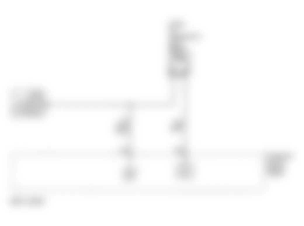
Isuzu Rodeo LS 1996 - DTC P0106 - MAP SENSOR SYSTEM PERFORMANCE

Fig. 1: Isuzu Rodeo LS 1996 - Component Locations - MAP Sensor Circuit (Rodeo 2.6L)
Isuzu Rodeo LS 1996 - Circuit Description
Powertrain Control Module (PCM) supplies a 5-volt reference signal and a ground circuit to Manifold Absolute Pressure (MAP) sensor. As manifold pressure changes, MAP sensor output voltage changes. MAP sensor output voltage should be 2 volts at idle and 4 volts at Wide Open Throttle (WOT).
Conditions required to test for DTC are:
- Idle speed does not vary more than 100 RPM.
- IAC does not vary more than 10 counts.
- TP sensor codes: P0121-P0123, P1121, P1122 are not present.
- TP sensor does not vary more than one percent.
- EGR is stable, changing less than four present.
- No status change in brake switch, A/C clutch, TCC or power steering pressure switch.
- MAP value change is greater 10 kPa from expected MAP value, for a total of 10 seconds.
Isuzu Rodeo LS 1996 - Diagnostic Procedures
- Perform On-Board Diagnostic (OBD) System Check. After performing OBD system check, go to next step.
- Turn ignition on, with engine off. Using scan tool, review FREEZE FRAME data and note parameters. Start engine and operate vehicle within conditions required for setting this DTC, and as close to conditions recorded in FREEZE FRAME as possible. If scan tool indicates DTC P0106 failed, go to step 4). If it indicates DTC P0106 did not fail, go to next step.
- Check for: MAP sensor seal missing of damaged, vacuum hoses (to MAP) disconnected, damaged or incorrectly routed, intake manifold vacuum leaks, throttle body leaks, EGR valve flange and pipe leaks, PCV faulty, missing or incorrectly installed. If no problem was found, refer to diagnostic aids.
- Disconnect MAP sensor connector and observe MAP value displayed on scan tool. If value is near 10 kPa, go to next step. If value is not near 10 kPa, go to step 13).
- Connect a test light between battery positive and MAP sensor signal circuit at sensor harness connector and observe MAP value on scan tool. If value is near 5 volts (104 kPa), go to next step. If value is not near 5 volts (104 kPa), go to step 9).
- Jumper 5 volt reference circuit and MAP signal circuit together at sensor harness connector. Observe MAP value displayed on scan tool. If value is near 5 volts (104 kPa), go to next step. If value is not near 5 volts (104 kPa), go to step 8).
- With ignition off, disconnect PCM and check sensor ground circuit for high resistance, open between PCM and MAP sensor, or poor connection at PCM. If no problem is found, go to step 11).
- With ignition off, check 5 volt reference circuit for high resistance, open between PCM and MAP sensor, or poor connection at PCM. If no problem is found, go to step 10).
- With ignition off, check MAP sensor signal circuit for high resistance, open short to ground, or short to sensor ground circuit. If no problem is found, go to next step.
- Check MAP sensor signal circuit for poor connection at PCM. If no problem is found, go to step 14).
- Check for poor connection at MAP sensor. If no problem is found, go to next step.
- Replace MAP sensor.
- Turn ignition off and disconnect PCM. With engine off, turn ignition on, check MAP signal circuit for a short to voltage or to 5 volt reference circuit. If no problem is found, go to next step.
- Replace PCM. Program replacement PCM using required equipment.
Isuzu Rodeo LS 1996 - Diagnostic Aids
Check for poor connection at PCM: Inspect harness connectors for backed-out terminals, improper mating, broken locks, improperly formed or damaged terminals and poor terminal to wire connection. Inspect wiring harness for damage. Move connectors and wiring harnesses related to sensor, while observing MAP display on scan tool. A change in display will indicate location of fault. If DTC can not be duplicated, failure records data can be used in determining vehicle mileage since DTC was last set. If it is determined that DTC occurs intermittently, performing DTC P1106 or P1107 may isolate cause of fault.
Isuzu Rodeo LS 1996 - DTC P0107 - MAP SENSOR CIRCUIT LOW VOLTAGE
NOTE: For circuit reference, see Code P0106 schematic.
Isuzu Rodeo LS 1996 - Circuit Description
Powertrain Control Module (PCM) supplies a 5-volt reference signal and a ground circuit to Manifold Absolute Pressure (MAP) sensor. As manifold pressure changes, MAP sensor output voltage changes. MAP sensor output voltage should be 2 volts at idle and 4 volts at Wide Open Throttle (WOT).
Conditions required to test for DTC are:
- TP sensor codes: P0121-P0123, P1121, P1122 are not present.
- Engine Is running.
- Throttle angle is above one percent, if engine speed is less than 1,000 RPM.
- Throttle angle is above two percent, if engine speed is above 1,000 RPM.
- MAP sensor indicates manifold absolute pressure below 11 kPa for a total of 10 seconds over a 16-second period.
Isuzu Rodeo LS 1996 - Diagnostic Procedures
- Perform On-Board Diagnostic (OBD) System Check. After performing OBD system check, go to next step.
- Turn ignition on, with engine off. With throttle closed, use scan tool to observe MAP sensor value. If MAP sensor value is near 101 kPa at sea level, go to step 4). If MAP sensor value is not near 101 kPa at sea level, go to next step.
- Turn ignition on, with engine off. Using scan tool, review FREEZE FRAME data and note parameters. Start engine and operate vehicle within conditions required for setting this DTC, and as close to conditions recorded in FREEZE FRAME as possible. If scan tool indicates DTC P0107 failed, go to next step. If it indicates DTC P0107 did not fail, go to refer to DIAGNOSTIC AIDS.
- With ignition off, disconnect MAP sensor electrical connector. Connect a jumper wire between 5 volt reference circuit and MAP signal circuit at sensor harness connector. Turn ignition on with engine off. Observe MAP value displayed on scan tool. If value is near 5 volts (104 kPa), go to step 10). If value is not near 5 volts (104 kPa), go to next step.
- Connect a test light between battery positive and MAP sensor signal circuit at sensor harness connector and observe MAP value on scan tool. If value is near 5 volts (104 kPa), go to next step. If value is not near 5 volts (104 kPa), go to step 8).
- With ignition off, disconnect PCM and check 5 volt reference circuit for open or short to ground. If no problem is found, go to next step.
- Check 5 volt reference circuit for poor connection at PCM. If no problem is found, go to step 11).
- Turn ignition off and disconnect PCM. Check MAP signal circuit for an open, short to ground or short to sensor ground circuit. If no problem is found, go to next step.
- With ignition off, check MAP sensor signal circuit for a poor connection at PCM and MAP sensor. If no problem is found, go to step 11).
- Replace MAP sensor.
- Replace PCM. Program replacement PCM using required equipment.
Isuzu Rodeo LS 1996 - Diagnostic Aids
Check for poor connection at PCM: Inspect harness connectors for backed-out terminals, improper mating, broken locks, improperly formed or damaged terminals and poor terminal to wire connection. Inspect wiring harness for damage. Move connectors and wiring harnesses related to sensor, while observing MAP display on scan tool. A change in display will indicate location of fault. If DTC can not be duplicated, failure records data can be used in determining vehicle mileage since DTC was last set. If it is determined that DTC occurs intermittently, performing DTC P0107 may isolate cause of fault.
Isuzu Rodeo LS 1996 - DTC P0108 - MAP SENSOR CIRCUIT HIGH VOLTAGE
NOTE: For circuit reference, see Code P0106 schematic.
Isuzu Rodeo LS 1996 - Circuit Description
Manifold Absolute Pressure (MAP) sensor measures changes in intake manifold pressure (vacuum). A low voltage signal, 2 volts, is sent to PCM on 5-volt reference circuit at closed throttle (high vacuum). A high voltage signal, 4 volts is sent at wide open throttle (low vacuum).
Conditions required to set DTC are:
- Engine running for predetermined time depending on coolant temperature at start-up. Predetermined time ranges from 0.5 second with ECT more than 86?F (30?C) to 2 minutes with ECT -22?F (-30?C).
- Engine at idle with engine speed less than 900 RPM.
- MAP sensor voltage more than 4.2 volts.
- No TP sensor DTCs are set.
- Listed conditions present for more than 58 crankshaft revolutions.
Isuzu Rodeo LS 1996 - Diagnostic Procedures
- Perform On-Board Diagnostic (OBD) System Check. Read and record FREEZE FRAME and/or FAIL RECORDS data for each DTC set. Go to next step.
- Correct any engine idle or vacuum problems before proceeding. Turn engine on and allow it to idle. Using scan tool, read MAP sensor voltage. If reading is more than 90 kPa, go to step 4). If reading is 90 kPa or less, go to next step.
- With ignition still on, engine off, use scan tool to read and record FAIL RECORDS data. Operate vehicle within conditions noted in FAIL RECORDS data. Using scan tool, read SPECIFIC DTC. If scan tool displays DTC P0108 FAILED THIS IGN, go to next step. If scan tool does not display DTC P0108 FAILED THIS IGN, go to DIAGNOSTIC AIDS.
- Turn ignition off. Disconnect MAP sensor harness connector. Turn ignition on. If voltage is zero volt, go to next step. If voltage is more than zero volt, go to step 6).
- Connect a test light between MAP sensor harness connector ground circuit and battery voltage. If test light illuminates, go tostep 7). If test light does not illuminate, go to step 9).
- Check MAP sensor harness connector signal circuit for short to voltage or a short to 5 volt reference. If short to voltage is found, repair as necessary. If short to voltage is not found, go to step 11).
- Check for faulty connection of ground circuit at MAP sensor. If faulty connection is found, repair as necessary. If connection is okay, go to next step.
- Check for plugged or leaking vacuum supply to MAP sensor. If plugged or leaking vacuum supply is found, repair as necessary. If not plugged or leaking, go to step 12).
- Check for faulty MAP sensor ground circuit connection at PCM. If faulty connection is found, repair as necessary. If connection is okay, go to next step.
- Check continuity of MAP sensor ground circuit. If resistance is over 5 ohms, repair circuit as necessary. If resistance is 5 ohms or less, go to next step.
- Replace PCM. Program replacement PCM using required equipment.
- Replace MAP sensor.
Isuzu Rodeo LS 1996 - Diagnostic Aids
Check for faulty connections or damaged harness. Ensure harness is not routed too close to high voltage wires, such as spark plug cables. If connections and harness appear okay, observe MAP display on scan tool while moving all related harness and connectors. A change in scan tool display indicates fault location. If DTC can not be duplicated, failure records data can be used in determining vehicle mileage since DTC was last set. If it is determined that DTC occurs intermittently, performing DTC P0107 may isolate cause of fault.
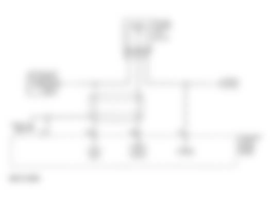
Isuzu Rodeo LS 1996 - DTC P0112 - IAT SENSOR CIRCUIT LOW VOLTAGE
Fig. 2: Isuzu Rodeo LS 1996 - Component Locations - IAT Sensor Circuit (Rodeo 2.6L)
Isuzu Rodeo LS 1996 - Circuit Description
Intake Air Temperature (IAT) sensor is a thermistor, which varies resistance based on temperature. As temperature of sensor increases, resistance decreases. High temperature will result in a low signal voltage. DTC will set when PCM sees an IAT sensor voltage of less than 0.82 volt for 10 seconds after engine runs for 100 seconds.
Conditions required to set DTC are:
- Vehicle driven at 30 MPH (48 kM/h) or more.
- Engine running more than 2 minutes.
- IAT indicates 298?F (148?C) (5 volts) for 12.5 seconds over a 25-second period of time.
- Above conditions are present for at least 2 seconds.
Isuzu Rodeo LS 1996 - Diagnostic Procedures
- Perform On-Board Diagnostic (OBD) System Check. Read and record FREEZE FRAME and/or FAIL RECORDS data for each DTC set. Go to next step.
- Turn ignition on. Using scan tool, read INTAKE AIR TEMP. If temperature is more than 283?F (148?C), go to step 4). If temperature is 283?F (148?C) or less, go to next step.
- Turn ignition on, engine off. Using scan tool, read and record FAIL RECORDS data. Operate vehicle within conditions noted in FAIL RECORDS data. Using scan tool, read SPECIFIC DTC. If scan tool displays DTC P0112 FAILED THIS IGN, go to next step. If scan tool does not display DTC P0112 FAILED THIS IGN, go to DIAGNOSTIC AIDS.
- Turn ignition off. Disconnect IAT sensor harness connector. Turn ignition back on. Using scan tool, read INTAKE AIR TEMP. If temperature is less than -36?F (-38?C), go to step 6). If temperature is -36?F (-38?C) or more, go to next step.
- Turn ignition off. Disconnect PCM connectors. Check IAT sensor signal circuit for short to ground. If short is found, go to step 7). If no short is found, go to step 8).
- Replace IAT sensor and go to step 9).
- Repair IAT sensor signal circuit and go to step 9).
- Replace PCM. Program replacement PCM using required equipment. Go to next step.
- Turn ignition on, engine off. Using scan tool, read and record FAIL RECORDS DATA, and clear DTCs. Operate vehicle within conditions noted in FAIL RECORDS data. Using scan tool, select SPECIFIC DTC INFO for DTC P0112. If scan tool displays DTC P0112 FAILED THIS IGN, return to step 2). If scan tool does not display DTC P0112 FAILED THIS IGN, repair is complete.
Isuzu Rodeo LS 1996 - Diagnostic Aids
Check for faulty connections or damaged harness. Ensure harness is not routed too close to high voltage wires, such as spark plug cables. If connections and harness appear okay, observe IAT display on scan tool while moving all related harness and connectors. A change in scan tool display indicates fault location.
Check for skewed IAT sensor. See IAT TEMPERATURE-TO-RESISTANCE VALUES in SENSOR RANGE CHARTS - 2.6L 4-CYL article.
Isuzu Rodeo LS 1996 - DTC P0113 - IAT SENSOR CIRCUIT HIGH VOLTAGE
NOTE: For circuit reference, see Code P0112 schematic.
Isuzu Rodeo LS 1996 - Circuit Description
Intake Air Temperature (IAT) sensor is a thermistor, which varies resistance based on temperature. As temperature of sensor increases, resistance decreases. Low temperature will result in a high signal voltage. DTC will set when PCM sees an IAT sensor voltage of greater than 5 volts.
Conditions required to set DTC are:
- Engine running for greater than 2 minutes.
- Vehicle speed is less than 1 MPH (2 kM/h).
- MAF value is less than 20 grams per second.
- ECT is greater than 140?F (60?C)
- IAT signal voltage indicates and intake air temperature less than -38?F (-39?C) for 12.5 seconds over a 25-second period.
Isuzu Rodeo LS 1996 - Diagnostic Procedures
- Perform On-Board Diagnostic (OBD) System Check. Read and record FREEZE FRAME and/or FAIL RECORDS data for each DTC set. Go to next step.
- Turn ignition on. Using scan tool, read INTAKE AIR TEMP. If temperature is less than -36?F (-38?C), go to step 4). If temperature is -36?F (-38?C) or greater, go to next step.
- Turn ignition on, engine off. Using scan tool, read and record FAIL RECORDS data. Operate vehicle within conditions noted in FAIL RECORDS data. Using scan tool, read SPECIFIC DTC. If scan tool displays DTC P0113 FAILED THIS IGN, go to next step. If scan tool does not display DTC P0113 FAILED THIS IGN, see DIAGNOSTIC AIDS.
- Disconnect IAT sensor harness connector. Connect a jumper wire between IAT sensor harness connector signal and ground circuits. Using scan tool, read INTAKE AIR TEMP. If temperature is 284?F (140?C), go to step 6). If temperature is not as specified, go to next step.
- Connect jumper wire between chassis ground and IAT sensor harness connector signal circuit. Using scan tool, read INTAKE AIR TEMP. If temperature is 284?F (140?C), go to step 7). If temperature is not as specified, go to step 8).
- Check for faulty connection at IAT sensor. If faulty connection is found, repair as necessary and go to step 12). If connection is okay, go to step 10).
- Turn ignition off. Disconnect PCM connectors. Check IAT sensor ground circuit for an open. If open is found, repair as necessary and go to step 12). If no open is found, go to step 9).
- Turn ignition off. Disconnect PCM connectors. Check IAT signal circuit for an open. If open circuit is found, repair as necessary and go to step 12). If no open is found, go to next step.
- Check for faulty IAT signal or ground circuit connection at PCM. If problem is found, repair as necessary and go to step 12). If no problem is found, go to step 11).
- Replace IAT sensor and go to step 12).
- Replace PCM. Program replacement PCM using required equipment. Go to next step.
- Turn ignition on, engine off. Using scan tool, read and record FAIL RECORDS DATA, and clear DTCs. Operate vehicle within conditions noted in FAIL RECORDS data. Using scan tool, select SPECIFIC DTC INFO for DTC P0113. If scan tool displays DTC P0113 FAILED THIS IGN, return to step 2). If scan tool does not display DTC P0113 FAILED THIS IGN, repair is complete.
Isuzu Rodeo LS 1996 - Diagnostic Aids
Check for faulty connections or damaged harness. Ensure harness is not routed too close to high voltage wires, such as spark plug cables. If connections and harness appear okay, observe IAT display on scan tool while moving all related harness and connectors. A change in scan tool display indicates fault location.
Check for skewed IAT sensor. See IAT TEMPERATURE-TO-RESISTANCE VALUES in SENSOR RANGE CHARTS - 2.6L 4-CYL article.
Isuzu Rodeo LS 1996 - DTC P0117 - ECT SENSOR CIRCUIT LOW VOLTAGE
Fig. 3: Isuzu Rodeo LS 1996 - Component Locations - ECT Sensor Circuit (Rodeo 2.6L)

Isuzu Rodeo LS 1996 - Circuit Description
Engine Coolant Temperature (ECT) sensor is a thermistor or a variable resistor, that varies resistance based on temperature. As temperature of sensor increases, resistance decreases. High temperature will result in a low signal voltage. DTC will set when PCM sees an excessively low ECT sensor voltage signal. ECT sensor will signal 1.5-2 volts when the engine is fully warmed.
Conditions required to set DTC are:
- Engine running greater than one minute.
- ECT greater than 302?F (150?C - .10 volts) for 50 seconds over a 100-second period.
Isuzu Rodeo LS 1996 - Diagnostic Procedures
- Perform On-Board Diagnostic (OBD) System Check. Read and record FREEZE FRAME and/or FAIL RECORDS data for each DTC set. Go to next step.
- Turn ignition on. Using scan tool, read ENG COOL TEMP. If temperature is less than 282?F (139?C), go to step 4). If temperature is 282?F (139?C) or greater, go to next step.
- Turn ignition on, engine off. Using scan tool, read and record FAIL RECORDS data. Operate vehicle within conditions noted in FAIL RECORDS data. Using scan tool, read SPECIFIC DTC. If scan tool displays DTC P0117 FAILED THIS IGN, go to next step. If scan tool does not display DTC P0117 FAILED THIS IGN, see DIAGNOSTIC AIDS.
- Disconnect ECT sensor harness connector. Using scan tool, read ENG COOL TEMP. If temperature is -38?F (-39?C), go to step 6). If temperature is not as specified, go to next step.
- Turn ignition off. Disconnect PCM connectors. Check ECT sensor signal circuit for short to ground or to sensor ground circuit. If short is found, repair as necessary and go to step 8). If no short is found, go to step 7).
- Replace ECT sensor and go to step 8).
- Replace PCM. Program replacement PCM using required equipment. Go to next step.
- Turn ignition on, engine off. Using scan tool, read and record FAIL RECORDS DATA, and clear DTCs. Operate vehicle within conditions noted in FAIL RECORDS data. Using scan tool, select SPECIFIC DTC INFO for DTC P0117. If scan tool displays DTC P0117 FAILED THIS IGN, return to step 2). If scan tool does not display DTC P0117 FAILED THIS IGN, repair is complete.
Isuzu Rodeo LS 1996 - Diagnostic Aids
Check for faulty connections or damaged harness. Ensure harness is not routed too close to high voltage wires, such as spark plug cables. If connections and harness appear okay, observe ECT display on scan tool while moving all related harness and connectors. A change in scan tool display indicates fault location.
Check for skewed ECT sensor. See ECT TEMPERATURE-TO-RESISTANCE VALUES.
Isuzu Rodeo LS 1996 - DTC P0118 - ECT SENSOR CIRCUIT HIGH VOLTAGE
NOTE: For circuit reference, see Code P0117 schematic.
Isuzu Rodeo LS 1996 - Circuit Description
Engine Coolant Temperature (ECT) sensor is a thermistor that varies resistance based on temperature. As temperature of sensor increases, resistance decreases. Low temperature will result in a high signal voltage. DTC will set when PCM sees an excessively high ECT sensor voltage signal. ECT sensor will signal 1.5-2 volts when the engine is fully warmed.
Conditions required to set DTC are:
- Engine running more than 1.5 minutes.
- Engine coolant temperature is -38?F (-39?C) (5 volts) or less, for 50 seconds over a 100-second period.
Isuzu Rodeo LS 1996 - Diagnostic Procedures
- Perform On-Board Diagnostic (OBD) System Check. Read and record FREEZE FRAME and/or FAIL RECORDS data for each DTC set. Go to next step.
- Turn ignition on, engine off. Read ECT display on scan tool. If temperature is less than -38?F (-39?C), go to step 4). If temperature is less than -38?F (-39?C), go to next step.
- Turn ignition on, engine off. Using scan tool, read and record FAIL RECORDS data. Operate vehicle within conditions noted in FAIL RECORDS data. Using scan tool, read SPECIFIC DTC. If scan tool displays DTC P0118 FAILED THIS IGN, go to next step. If scan tool does not display DTC P0118 FAILED THIS IGN, go to DIAGNOSTIC AIDS.
- Disconnect ECT sensor harness connector. Connect a jumper wire between ECT sensor harness connector signal and ground circuits. Using scan tool, read ENG COOL TEMP. If temperature is 284?F (140?C), go to step 6). If temperature is not as specified, go to next step.
- Connect jumper wire between chassis ground and ECT sensor harness connector signal circuit. Using scan tool, read ENG COOL TEMP. If temperature is 284?F (140?C), go to step 7). If temperature is not as specified, go to step 8).
- Check for faulty connection at ECT sensor. If faulty connection is found, repair as necessary and go to step 12). If connection is okay, go to step 10).
- Turn ignition off. Disconnect PCM connectors. Check ECT sensor ground circuit for an open. If open is found, repair as necessary and go to step 12). If no open is found, go to step 9).
- Turn ignition off. Disconnect PCM connectors. Check ECT signal circuit for an open. If open is found, repair as necessary and go tostep 12). If no open is found, go to next step.
- Check for faulty ECT signal or ground circuit connection at PCM. If problem is found, repair as necessary and go to step 12). If no problem is found, go to step 11).
- Replace ECT sensor and go to step 12).
- Replace PCM. Program replacement PCM using required equipment. Go to next step.
- Turn ignition on, engine off. Using scan tool, read and record FAIL RECORDS DATA, and clear DTCs. Operate vehicle within conditions noted in FAIL RECORDS data. Using scan tool, select SPECIFIC DTC INFO for DTC P0118. If scan tool displays DTC P0118 FAILED THIS IGN, return to step 2). If scan tool does not display DTC P0118 FAILED THIS IGN, repair is complete.
Isuzu Rodeo LS 1996 - Diagnostic Aids
Check for faulty connections or damaged harness. Ensure harness is not routed too close to high voltage wires, such as spark plug cables. If connections and harness appear okay, observe ECT display on scan tool while moving all related harness and connectors. A change in scan tool display indicates fault location.
Check for skewed ECT sensor. See ECT TEMPERATURE-TO-RESISTANCE VALUES.
Isuzu Rodeo LS 1996 - DTC P0121 - TP SENSOR SYSTEM PERFORMANCE
Fig. 4: Isuzu Rodeo LS 1996 - Component Locations - TP Sensor Circuit (Rodeo 2.6L)
Isuzu Rodeo LS 1996 - Circuit Description
Throttle Position (TP) sensor measures amount of throttle opening. PCM uses TP sensor information for fuel delivery calculations. TP sensor readings during wide open throttle are 4 volts and one volt at idle.
Conditions required to set DTC are:
- Engine running and throttle steady at less than one percent.
- No P0106, P0107, P0108, P0122 or P0123 DTCs are set
- MAP reading below 55 kPa.
- Predicted TP ANGLE not close to actual TP ANGLE.
- Above conditions present for 12.5 seconds over a 25-second period.
Isuzu Rodeo LS 1996 - Diagnostic Procedures
- Perform On-Board Diagnostic (OBD) System Check. Read and record FREEZE FRAME and/or FAIL RECORDS data for each DTC set. Go to next step.
- Turn ignition on, engine off. Using scan tool, read MAP value. If value is less than 65 kPa, go to next step. If value is 65 kPa or more, go to step 6).
- Disconnect MAP sensor harness connector. Connect a test light between MAP sensor harness connector 5-volt reference and signal circuits. Using scan tool, read MAP value. If value is less than 65 kPa, go to step 5). If value is 65 kPa or more, go to next step.
- Check MAP sensor signal circuit for open or short between PCM and MAP sensor. If problem is found, repair as necessary and go to step 13). If no problem is found, go to step 12).
- Replace MAP sensor and go to step 13).
- Observe scan tool TP ANGLE value while moving throttle from closed to wide open. If value increases steadily and evenly from closed to open throttle, go to DIAGNOSTIC AIDS. If value does not change as specified, go to next step.
- Disconnect TP sensor harness connector. If value is zero, go to next step. If value is more than 0%, go to step 9).
- Connect a test light between TP sensor harness connector 5-volt reference circuit and signal circuit. Using scan tool, read TP sensor voltage. If scan tool voltage is 5 volts, go to step 11). If voltage is not about 5 volts, go to step 10).
- Check TP sensor signal circuit for short to ground, and ground circuit for high resistance and poor connection. If a problem is found, repair as necessary and go to step 13). If no problem is found, go to step 12).
- Check TP sensor 5-volt reference circuit for poor connection or high resistance between PCM and TP sensor. If a problem is found, repair as necessary and go to step 13). If no problem is found, go to step 12).
- Replace TP sensor and go to step 13).
- Replace PCM. Program replacement PCM using required equipment. Go to next step.
- Turn ignition on, engine off. Using scan tool, read and record FAIL RECORDS DATA, and clear DTCs. Operate vehicle within conditions noted in FAIL RECORDS data. Using scan tool, select SPECIFIC DTC INFO for DTC P0117. If scan tool displays DTC P0117 FAILED THIS IGN, return to step 2). If scan tool does not display DTC P0117 FAILED THIS IGN, repair is complete.
Isuzu Rodeo LS 1996 - Diagnostic Aids
Check for and repair the following condition(s):
- Throttle plate sticking or excessive deposits on throttle plate or throttle bore.
- Check TP sensor harness connector terminals for damage.
- A steady throttle movement from a stop should cause TP ANGLE value reading on scan tool to increase smoothly as throttle is opened.
Check for faulty connections or damaged harness. Ensure harness is not routed too close to high voltage wires, such as spark plug cables. If connections and harness appear okay, observe ECT display on scan tool while moving all related harness and connectors. A change in scan tool display indicates fault location. Check for skewed MAP signal or faulty MAP sensor by comparing scan tool values to a known-good similar vehicle.
Isuzu Rodeo LS 1996 - DTC P0122 - TP SENSOR CIRCUIT LOW VOLTAGE
NOTE: For circuit reference, see Code P0121 schematic.
Isuzu Rodeo LS 1996 - Circuit Description
Throttle Position (TP) sensor measures amount of throttle opening. PCM uses TP sensor information for fuel delivery calculations. TP sensor readings during wide open throttle are 4 volts and one volt at idle.
Condition required to test for DTC is:
- TP sensor signal voltage is less than .22 volts for .78 second over a 1.5-secnod period.
- Ignition is on.
Isuzu Rodeo LS 1996 - Diagnostic Procedures
- Perform On-Board Diagnostic (OBD) System Check. Read and record FREEZE FRAME and/or FAIL RECORDS data for each DTC set. Go to next step.
- Turn ignition on, engine off. With throttle closed, use scan tool to read TP sensor voltage. If voltage is less than 0.22 volt, go to step 4). If voltage is 0.22 volt or greater, go to next step.
- With ignition still on, engine off, use scan tool to read and record FAIL RECORDS data. Operate vehicle within conditions noted in FAIL RECORDS data. Using scan tool, read SPECIFIC DTC. If scan tool displays DTC P0122 FAILED THIS IGN, go to next step. If scan tool does not display DTC P0122 FAILED THIS IGN, see DIAGNOSTIC AIDS.
- Turn ignition off.Disconnect TP sensor harness connector. Connect a jumper wire between TP sensor harness connector 5-volt reference and signal circuits. Turn ignition on. If voltage is 5 volts, go to step 10). If voltage is not 5 volts, go to next step.
- Turn ignition off. Remove jumper wire. Connect a test light between TP sensor harness connector signal circuit and battery voltage. If reading is not 5 volts, go to step 8). If display indicates 5 volts, go to next step.
- Turn ignition off. Disconnect PCM connectors. Check PCM harness connector 5-volt reference circuit for open or short to ground. If open or short is found, repair as necessary and go to step 13). If no open or short is found, go to next step.
- Turn ignition off. Check for faulty connection of 5-volt reference circuit at PCM. If faulty connection is found, repair as necessary and go to step 13). If connection is okay, go to step 12).
- Turn ignition off. Disconnect PCM connectors. Check PCM harness connector TP signal circuit for open or short to ground. If open or short is found, repair as necessary and go to step 13). If no open or short is found, go to next step.
- Check for faulty connection of TP signal circuit at PCM. If faulty connection is found, repair as necessary and go to step 13). If connection is okay, go to step 12).
- Check for faulty connection of TP signal circuit at TP sensor. If faulty connection is found, repair as necessary and go to step 13). If connection is okay, go to next step.
- Replace TP sensor and go to step 13).
- Replace PCM. Program replacement PCM using required equipment. Go to next step.
- Turn ignition on, engine off. Using scan tool, read and record FAIL RECORDS DATA, and clear DTCs. Operate vehicle within conditions noted in FAIL RECORDS data. Using scan tool, select SPECIFIC DTC INFO for DTC P0122. If scan tool displays DTC P0122 FAILED THIS IGN, return to step 2). If scan tool does not display DTC P0122 FAILED THIS IGN, repair is complete.
Isuzu Rodeo LS 1996 - Diagnostic Aids
Check for faulty connections or damaged harness. Ensure harness is not routed too close to high voltage wires, such as spark plug cables. If connections and harness appear okay, observe TP SENSOR display on scan tool while moving all related harness and connectors. A change in scan tool display indicates fault location.
Isuzu Rodeo LS 1996 - DTC P0123 - TP SENSOR CIRCUIT HIGH VOLTAGE
NOTE: For circuit reference, see Code P0121 schematic.
Isuzu Rodeo LS 1996 - Circuit Description
Throttle Position (TP) sensor measures amount of throttle opening. PCM uses TP sensor information for fuel delivery calculations. TP sensor readings during wide open throttle are 4 volts and one volt at idle.
Conditions required to set DTC are:
- Ignition on.
- TP sensor signal voltage more than 4.88 volts for .78 second over a 1.5-second period.
Isuzu Rodeo LS 1996 - Diagnostic Procedures
- Perform On-Board Diagnostic (OBD) System Check. Read and record FREEZE FRAME and/or FAIL RECORDS data for each DTC set. Go to next step.
- Turn ignition on, engine off. Using scan tool, read TP sensor voltage. If voltage is more than 4.88 volts, go to step 4). If voltage is 4.88 volts or less, go to next step.
- With ignition still on, engine off, using scan tool, read and record FAIL RECORDS data. Operate vehicle within conditions noted in FAIL RECORDS data. Using scan tool, read SPECIFIC DTC. If scan tool displays DTC P0123 FAILED THIS IGN, go to next step. If scan tool does not display DTC P0123 FAILED THIS IGN, go to DIAGNOSTIC AIDS.
- Disconnect TP sensor harness connector. If voltage is about zero volt, go to next step. If voltage is not as specified, go to step 6).
- Connect a test light between TP sensor harness connector ground circuit and battery voltage. If test light illuminates, go to step 7). If test light does not illuminate, go to step 10).
- Turn ignition off. Disconnect PCM connectors. Turn ignition on. Check TP sensor harness connector signal circuit for short to voltage. If short to voltage is found, repair as necessary and go to step 13). If short to voltage is not found, go to step 12).
- Turn ignition on. While monitoring scan tool TP SENSOR display, disconnect each component (one at a time) that shares common 5-volt reference circuit. If display changes, replace component that causes change and go to step 13). If display does not change, go to next step.
- Turn ignition off. Disconnect PCM connectors. Turn ignition on, engine off. Check PCM harness connector 5-volt reference circuit for short to voltage. If short is found, repair as necessary and go tostep 13). If no short is found, go to next step.
- Check for faulty connection at TP sensor. If faulty connection is found, repair as necessary and go to step 13). If connection is okay, go to step 11).
- Turn ignition off. Disconnect PCM connectors. Check for faulty TP sensor ground circuit connection at PCM. If faulty connection is found, repair as necessary and go to step 13). If connection is okay, go tostep 12).
- Replace TP sensor and go to step 13).
- Replace PCM. Program replacement PCM using required equipment. Go to next step.
- Turn ignition on, engine off. Using scan tool, read and record FAIL RECORDS DATA, and clear DTCs. Operate vehicle within conditions noted in FAIL RECORDS data. Using scan tool, select SPECIFIC DTC INFO for DTC P0123. If scan tool displays DTC P0123 FAILED THIS IGN, return to step 2). If scan tool does not display DTC P0123 FAILED THIS IGN, repair is complete.
Isuzu Rodeo LS 1996 - Diagnostic Aids
Check for faulty connections or damaged harness. Ensure harness is not routed too close to high voltage wires, such as spark plug cables. If connections and harness appear okay, observe TP SENSOR display on scan tool while moving all related harness and connectors. A change in scan tool display indicates fault location.
Turn ignition on, engine off. Using scan tool TP SENSOR display, slowly depress accelerator to wide open throttle. If voltage is more than 4.71 volts at any time, replace TP sensor.
Isuzu Rodeo LS 1996 - DTC P0125 - ECT EXCESSIVE TIME TO REACH CLOSED LOOP
NOTE: For circuit reference, see Code P0117 schematic.
While engine is warming, PCM reads Engine Coolant Temperature (ECT) sensor to determine how long it takes coolant to reach temperature required for closed loop operation. PCM compares actual time required to a predetermined time.
Conditions required to set DTC are:
- Vehicle speed is greater than 5 MPH (8 kM/h).
- No P0112, P0113, P0117, P0118, P111, P1112, P1114 or P1115 are set.
- Start-up IAT greater than 32?F (0?C).
- Start-up engine coolant temperature between -5-84?F (-20.5-29?C).
- Closed loop operation temperature of 84?F (29?C) not reached within 2 minutes of start-up.
Isuzu Rodeo LS 1996 - Diagnostic Procedures
- Perform On-Board Diagnostic (OBD) System Check. Read and record FREEZE FRAME and/or FAIL RECORDS data for each DTC set. Go to next step.
- If any ECT DTCs are set, diagnose affected DTC before proceeding. If no ECT DTCs are set, go to next step.
- Check coolant level. If coolant level is low, go to step 9) If coolant level is okay, go to next step.
- Allow engine to cool completely. Turn engine on and allow it to idle. Using scan tool, monitor ENG COOL TEMP. If temperature increases to 70?F (21?C) within 2 minutes, see DIAGNOSTIC AIDS. If specified temperature is not reached within 2 minutes, go to next step.
- Check thermostat operation. If thermostat is operating correctly, go to next step. If thermostat is not operating correctly, go to step 9).
- Compare actual coolant temperature with scan tool ECT value. If temperatures are close in value, go to step 9). If temperatures are not close in value, go to next step.
- Turn ignition off. Disconnect PCM. Using a DVOM, measure ECT resistance at PCM connector and compare DVOM readings with ECT SENSOR TEMPERATURE VS. RESISTANCE VALUES table. If chart values equal readings, go to step 12). If chart values do not equal readings, go to next step.
- Check for high resistance in wiring related to ECT sensor and for poor connections at ECT sensor and PCM. If a problem is found, go to step 10). If no problem is found, go to step 11).
- Repair cooling system as necessary and go to step 13).
- Repair terminal as necessary and go to step 13).
- Replace ECT sensor and go to step 13) .
- Replace PCM and go to next step.
- Allow engine to cool completely. Using scan tool, clear DTCs. Turn engine on and allow it to idle. Using scan tool, monitor ENG COOL TEMP. If temperature increases to 71.6?F (22?C) within 2 minutes, repair is complete. If specified temperature is not reached within 2 minutes, return to step 2).
Isuzu Rodeo LS 1996 - Diagnostic Aids
Check coolant level. Ensure thermostat and cooling fans are operating properly. Check for high resistance in wiring related to ECT sensor. Check for skewed ECT sensor by comparing actual coolant temperature with scan tool display, and replace ECT sensor if temperatures are not close.
Check for faulty connections or damaged harness. If connections and harness appear okay, observe scan tool while moving all related harness and connectors. A change in scan tool display indicates fault location.
Isuzu Rodeo LS 1996 ECT SENSOR TEMPERATURE VS. RESISTANCE VALUES
?F ?C OHMS 212 100 177 176 80 332 140 60 667 113 45 1188 95 35 1802 77 25 2796 59 15 4450 41 5 7280 23 -5 12300 5 -15 21450 -22 -30 52700 -40 -40 100700
Isuzu Rodeo LS 1996 - DTC P0131 - HO2S CIRCUIT LOW VOLTAGE SENSOR 1
Fig. 5: Isuzu Rodeo LS 1996 - Component Locations - HO2 Sensor 1 Circuit Schematic (Rodeo 2.6L)

Isuzu Rodeo LS 1996 - Circuit Description
PCM provides about 0.35 volt reference to Heated Oxygen Sensor (HO2S). HO2S sensor signal voltage varies from about one volt when exhaust is rich to about 0.1 volt when exhaust is lean. PCM reads and stores sensor voltage information and evaluates the voltage samples to determine amount of time sensor voltage is out of range. If HO2S voltage is out of predetermined range, DTC will set.
Conditions required to set DTC are:
- No CKP, ECT, EGR pintle position, IAT, MAF, MAP or TP sensor DTCs set.
- No EVAP system DTC set.
- No fuel injector circuit, fuel trim or misfire DTCs set.
- Closed loop commanded air/fuel ratio is 14.5-14.8:1.
- TP angle is 3-19%.
- HO2S signal voltage is below 26 mV at closed loop, for 77 seconds over a 90-second period.
- ECT is above 140?F (60?C)
Isuzu Rodeo LS 1996 - Diagnostic Procedures
- Perform On-Board Diagnostic (OBD) System Check. Read and record FREEZE FRAME and/or FAIL RECORDS data for each DTC set. Go to next step.
- Start engine and allow it to reach operating temperature. Operate vehicle under conditions required to set DTC. Using scan tool, read HO2S 1 voltage. If voltage stays less than 0.3 volt, go to step 4). If voltage stays 0.3 volt or greater, go to next step.
- Turn engine off. Turn ignition on, engine off. Using scan tool, read and record FAIL RECORDS data. Operate vehicle within conditions noted in FAIL RECORDS data. Using scan tool, read SPECIFIC DTC. If scan tool displays DTC P0131 FAILED THIS IGN, go to next step. If scan tool does not display DTC P0131 FAILED THIS IGN, see DIAGNOSTIC AIDS.
- Turn ignition off. Disconnect PCM connectors. Check HO2S sensor harness connector signal circuit for short to ground. If short is found, go to next step. If no short is found, go to step 6).
- Repair signal circuit as necessary and go to step 10).
- Turn ignition off. Check for continuity between high and low circuits. If continuity found, go to next step. If continuity is not found, go to step 7).
- Repair short between high and low circuits, than go to step 10).
- Turn ignition off. Reconnect PCM harness connector, leaving sensor disconnected, and turn ignition back on. If scan tool reads 430-450 mV refer to DIAGNOSTIC AIDS. If scan tool does not read 430-450 mV, go to next step.
- Replace PCM. Program replacement PCM using required equipment. Go to next step.
- Turn ignition on, engine off. Using scan tool, read and record FAIL RECORDS DATA, and clear DTCs. Operate vehicle within conditions noted in FAIL RECORDS data. Using scan tool, select SPECIFIC DTC INFO for DTC P0131. If scan tool displays DTC P0131 FAILED THIS IGN, return to step 2). If scan tool does not display DTC P0131 FAILED THIS IGN, repair is complete.
Isuzu Rodeo LS 1996 - Diagnostic Aids
Ensure HO2S 1 sensor harness is routed correctly and not contacting exhaust system. Check for faulty PCM grounds. Perform A-6, FUEL SYSTEM DIAGNOSIS under BASIC FUEL SYSTEM CHECKS in appropriate BASIC TESTING - 2.6L 4-CYL article. Perform A-7, INJECTOR BALANCE TEST under FUEL SYSTEM in SYSTEM & COMPONENT TESTING.
Check for vacuum leaks at intake manifold, throttle body, EGR system and crankcase ventilation system. Check for exhaust leaks in front of HO2S 1. Disconnect MAF sensor connector and see if lean condition is corrected. If lean condition is corrected, replace MAF sensor. Check for fuel contamination. If none of previous conditions are present, replace HO2S 1.
Isuzu Rodeo LS 1996 - DTC P0132 - HO2S CIRCUIT HIGH VOLTAGE SENSOR 1
NOTE: For circuit reference, see Fig. 5 , Code P0131 schematic.
Isuzu Rodeo LS 1996 - Circuit Description
PCM provides about 0.45 volt reference to Heated Oxygen Sensor (HO2S). HO2S sensor signal voltage varies from about one volt when exhaust is rich to about 0.1 volt when exhaust is lean. PCM reads and stores sensor voltage information and evaluates the voltage samples to determine amount of time sensor voltage is out of range. If HO2S voltage is out of predetermined range, DTC will set.
Conditions required to set DTC are:
- No CKP, ECT, EGR pintle position, IAT, MAF, MAP or TP sensor DTCs set.
- No EVAP system DTC set.
- No fuel injector circuit, fuel trim or misfire DTCs set.
- ECT above 140?F (60?C).
- Closed loop commanded air/fuel ratio is 14.5-14.8:1.
- TP ANGLE is 3-19%.
- HO2S 1 signal voltage stays greater than 952 mV during closed loop operation for 77 seconds over a 90-second period.
Or
- HO2S 1 signal voltage stays greater than 500 mV during deceleration fuel cutoff mode operation for 5 seconds.
Isuzu Rodeo LS 1996 - Diagnostic Procedures
- Perform On-Board Diagnostic (OBD) System Check. Read and record FREEZE FRAME and/or FAIL RECORDS data for each DTC set. Go to next step.
- Start engine and allow it to reach operating temperature. Operate vehicle under conditions required to set DTC. Using scan tool, read HO2S 1 voltage. If voltage stays greater than 952 mV (500 mV in deceleration fuel cutoff mode), go to step 4). If voltage stays 952 mV (500 mV in deceleration fuel cutoff mode) or less, go to next step.
- Turn ignition on, engine off. Using scan tool, read and record FAIL RECORDS data. Operate vehicle within conditions noted in FAIL RECORDS data. Using scan tool, read SPECIFIC DTC. If scan tool displays DTC P0132 FAILED THIS IGN, go to next step. If scan tool does not display DTC P0132 FAILED THIS IGN, see DIAGNOSTIC AIDS.
- Turn ignition off. Disconnect HO2S harness connector and turn ignition back on. Using a DVOM measure voltage at high and low signal terminals. If readings are 5-14 volts, go to next step. If readings are not 5-14 volts go to step 6).
- Repair short to voltage in signal circuit, than go to step 10).
- Turn ignition off. Disconnect PCM connectors. Inspect PCM pins and terminals for damage. Repair as necessary, than go to step 10).
- Turn ignition on with engine off. Disconnect HO2S and connect a jumper between HO2S high, low and ground. Using a scan tool read HO2S voltage. If reading is below 10 mV, go to next step. If reading is at 10 mV or above, go to step 9).
- Replace HO2S, than go to step 10).
- Replace PCM. Program replacement PCM using required equipment. After repairs, go to next step.
- Turn ignition on, engine off. Using scan tool, read and record FAIL RECORDS DATA, and clear DTCs. Operate vehicle within conditions noted in FAIL RECORDS data. Using scan tool, select SPECIFIC DTC INFO for DTC P0132. If scan tool displays DTC P0132 FAILED THIS IGN, return to step 2). If scan tool does not display DTC P0132 FAILED THIS IGN, repair is complete.
Isuzu Rodeo LS 1996 - Diagnostic Aids
Ensure HO2S 1 sensor harness is routed correctly and not contacting exhaust system. Check for open or short in HO2S 1 signal or ground circuits. Check for internally shorted HO2S 1. Check HO2S 1 for silicon (powdery white deposit) contamination. Check for faulty PCM grounds. Perform A-6, FUEL SYSTEM DIAGNOSIS under BASIC FUEL SYSTEM CHECKS in BASIC TESTING - 2.6L 4-CYL article. Perform A-7, INJECTOR BALANCE TEST under FUEL SYSTEM in appropriate SYSTEM/COMPONENT TESTS - 2.6L 4-CYL article.
Check EVAP canister for fuel saturation. Disconnect MAF sensor connector and see if rich condition is corrected. If rich condition is corrected, replace MAF sensor. Check for fuel in fuel pressure regulator vacuum line.
Isuzu Rodeo LS 1996 - DTC P0133 - HO2S SLOW RESPONSE SENSOR 1
NOTE: For circuit reference, see Fig. 5 , Code P0131 schematic.
Isuzu Rodeo LS 1996 - Circuit Description
PCM provides about 0.45 volt reference to Heated Oxygen Sensor (HO2S). HO2S sensor signal voltage varies from about one volt when exhaust is rich to about 0.1 volt when exhaust is lean. PCM counts number or times a rich-to-lean and lean-to-rich response is indicated and adds amount of time it takes to complete all transitions. PCM uses this information to determine average time for each transition. If average response time is slow, DTC P0133 will set.
Conditions required to set DTC are:
- No CKP, ECT, EGR pintle position, IAT, MAF, MAP or TP sensor DTCs set.
- No EVAP system DTC set.
- No fuel injector circuit, fuel trim or misfire DTCs set.
- Engine running in closed loop fuel control mode for at least 1 minute.
- Engine speed 1500-3000 RPM.
- ECT greater than 122?F (50?C).
- Canister purge duty cycle is greater than two percent.
- MAF 9-42 grams per second.
- 90 seconds after closed loop has been established, HO2S an average transition time between 300-600 mV is too slow.
- Lean-to-rich average transition response time greater than 100 milliseconds.
- Rich-to-lean average transition response time greater than 150 milliseconds.
Isuzu Rodeo LS 1996 - Diagnostic Procedures
- Perform On-Board Diagnostic (OBD) System Check. Read and record FREEZE FRAME and/or FAIL RECORDS data for each DTC set. Go to next step.
NOTE: If any DTC except for P0153, P1133, P1134, P1153 and P1154 are set refer to those DTCs first. - Start engine and allow it to reach operating temperature. Operate vehicle within conditions required to set DTC. Using scan tool, read SPECIFIC DTC. If scan tool displays DTC P0133 FAILED THIS IGN, go to next step. If scan tool does not display DTC P0133 FAILED THIS IGN, see DIAGNOSTIC AIDS.
- If scan tool also displays DTC P0153, P1133, P1134, P1153 or P1154 FAILED THIS IGN, go to step 8). If scan tool does not display these DTCs, go to next step.
- Visually inspect exhaust system for leaks near HO2S 1. If leaks are found, repair as necessary and return to step 2). If no leaks are found, go to next step.
- Visually inspect HO2S 1 for secure installation or corrosion on terminals. Check terminal tension at HO2S 1 and PCM. Check for damaged wiring. If a problem is found, go to step 9). If no problem is found, go to next step.
- Disconnect HO2S 1 connector. Using a DVOM measure voltage between high signal circuit and ground and low signal circuit and ground. If voltage is 3-4 volts, go to next step. If voltage is not as specified, go to step 10).
- Connect a jumper wire between HO2S 1 harness connector high signal, low signal and ground. Turn ignition on. Using scan tool read voltage. If voltage is less than 10 mV and immediately returns to 450 mV when jumper wire is removed, go to step 12). If not as specified, go to step 13).
- Replace affected HO2S and go to step 14).
NOTE: Before replacing HO2S, correct cause of HO2S contamination. - Repair condition as necessary and go to step 14).
- Inspect PCM connections and terminals for damage. Repair as necessary and go to step 14). If PCM connections and terminals are in good condition, go to next step.
- Repair open, short or grounded HO2S 1 signal circuit, and go to step 14).
- Replace HO2S 1 and go to step 14).
- Replace PCM. Program replacement PCM using required equipment. After repairs, go to next step.
- Using scan tool, read and record FAIL RECORDS DATA, and clear DTCs. Operate vehicle within conditions noted in FAIL RECORDS data. Using scan tool, select SPECIFIC DTC INFO for DTC P0133. If scan tool displays DTC P0133 FAILED THIS IGN, return to step 2). If scan tool does not display DTC P0133 FAILED THIS IGN, repair is complete.
Isuzu Rodeo LS 1996 - Diagnostic Aids
Check for faulty connections or damaged harness. If connections and harness appear okay, observe HO2S 1 display on scan tool while moving all related harness and connectors. A change in scan tool display indicates fault location.
Isuzu Rodeo LS 1996 - DTC P0134 - HO2S INSUFFICIENT ACTIVITY SENSOR 1
NOTE: For circuit reference, see Fig. 5 , Code P0131 schematic.
Isuzu Rodeo LS 1996 - Circuit Description
PCM provides about 0.45 volt reference to Heated Oxygen Sensor (HO2S). HO2S sensor signal voltage varies from about one volt when exhaust is rich to about 0.1 volt when exhaust is lean. PCM reads and stores sensor voltage information and evaluates the voltage samples to determine amount of time sensor voltage is out of range. If HO2S voltage is out of predetermined range, DTC will set.
Conditions required to set DTC are:
- No CKP, ECT, EGR pintle position, IAT, MAF, MAP or TP sensor DTCs set.
- No EVAP system DTC set.
- No fuel injector circuit, fuel trim or misfire DTCs set.
- Battery voltage is greater than 10 volts.
- HO2S heater has been determined to be functioning properly.
- Engine running for at least 40 seconds.
- HO2S 1 signal voltage signal voltage stays 0.4-0.5 volt for 77 seconds over a 90-second period.
Isuzu Rodeo LS 1996 - Diagnostic Procedures
- Perform On-Board Diagnostic (OBD) System Check. Read and record FREEZE FRAME and/or FAIL RECORDS data for each DTC set. Go to next step.
- Start engine and allow it to reach normal operating temperature. Apply parking brake and increase engine speed to greater than 1200 RPM for 3 minutes. Using scan tool, read HO2S 1 voltage. If voltage is not 0.4-0.5 volt, go to next step. If voltage is not 0.4-0.5 volt, go to step 4).
- Turn engine off. Turn ignition on, engine off. Using scan tool, read and record FAIL RECORDS data. Operate vehicle within conditions noted in FAIL RECORDS data. Using scan tool, read SPECIFIC DTC. If scan tool displays DTC P0134 FAILED THIS IGN, go to next step. If scan tool does not display DTC P0134 FAILED THIS IGN, see DIAGNOSTIC AIDS.
- Inspect sensor harness for damage.
- Check for faulty connection at HO2S 1 signal and ground circuit. If faulty connection is found, repair as necessary and go to step 12). If connection is okay, go to next step.
- Check for faulty connection at PCM signal and ground circuit. If faulty connection is found, repair as necessary and go to step 12). If connection is okay, go to next step.
- Turn ignition off. Disconnect PCM connectors. Check resistance of HO2S 1 harness connector signal circuit. If resistance is greater than .5 ohms, repair open or faulty connection as necessary and go tostep 12). If resistance is .5 ohms or less, go to next step.
- Turn ignition off. Disconnect PCM connectors. Check resistance of HO2S 1 harness connector ground circuit. If resistance is greater than 5 ohms, repair open or faulty connection as necessary and go tostep 12). If resistance is 5 ohms or less, go to next step.
- Turn ignition on, engine off. Disconnect HO2S harness connector, connect a jumper wire between HO2S 1 harness connector signal and ground circuits, and chassis ground. Using a scan tool read voltage, If voltage is 0.10 volt, go to next step. If voltage is not 0.10 volt, go to step 11).
- Replace HO2S 1 and go to step 12).
- Replace PCM. Program replacement PCM using required equipment. After repairs, go to next step.
- Using scan tool, read and record FAIL RECORDS DATA, and clear DTCs. Operate vehicle within conditions noted in FAIL RECORDS data. Using scan tool, select SPECIFIC DTC INFO for DTC P0134. If scan tool displays DTC P0134 FAILED THIS IGN, return to step 2). If scan tool does not display DTC P0134 FAILED THIS IGN, repair is complete.
Isuzu Rodeo LS 1996 - Diagnostic Aids
Check for faulty connections or damaged harness. If connections and harness appear okay, observe HO2S 1 display on scan tool while moving all related harness and connectors. A change in scan tool display indicates fault location. Check HO2S 1 heater operation.
Isuzu Rodeo LS 1996 - DTC P0135 - HO2S HEATER CIRCUIT SENSOR 1
NOTE: For circuit reference, see Fig. 5 , Code P0131 schematic.
Isuzu Rodeo LS 1996 - Circuit Description
PCM provides about 0.45 volt reference to Heated Oxygen Sensor (HO2S). HO2S sensor signal voltage varies from about one volt when exhaust is rich to about 0.1 volt when exhaust is lean. When ignition is turned on, battery voltage is supplied to HO2S heater to provide for faster sensor warm-up, thus allowing sensor to become active in a shorter period of time. PCM reads amount of time necessary for sensor to become active after start-up.
Conditions required to set DTC are:
- No CKP, ECT, EGR pintle position, IAT, MAF, MAP or TP sensor DTCs set.
- No EVAP system DTC set.
- No fuel injector circuit, fuel trim or misfire DTCs set.
- ECT and IAT less than 90?F (32?C) at start-up.
- Difference between ECT and IAT no greater than 14?F (8?C).
- Ignition voltage is between 10-18 volts.
- MAF less than 64 grams per second.
- HO2S 1 voltage remains within 0.15 volt of bias voltage (0.45 volt) for longer amount of time than it should.
Isuzu Rodeo LS 1996 - Diagnostic Procedures
- Perform On-Board Diagnostic (OBD) System Check. Read and record FREEZE FRAME and/or FAIL RECORDS data for each DTC set. Go to next step.
NOTE: If engine has been operating, allow engine to cool for about 30 minutes before proceeding with tests. - Turn ignition on, engine off. Using scan tool, read HO2S 1 voltage. If voltage is greater than 0.65 volt or less than 0.25 volt, see DIAGNOSTIC AIDS. If voltage is not as specified, go to next step.
- Inspect HO2S 1 ignition feed fuse. If fuse is open, go to step 15). If fuse is okay, go to next step.
- Turn ignition off. Raise and support vehicle. Disconnect HO2S 1 harness connector. Connect a test light between chassis ground andHO2S 1 ignition feed circuit. If test light illuminates, go to next step. If test light does not illuminate, go to step 7).
- Connect test light between HO2S 1 harness connector ignition feed and heater ground circuits. If test light illuminates, go to next step. If test light does not illuminate, go to step 8).
- Allow HO2S 1 to cool for at least 10 minutes. Using DVOM, check resistance between ignition feed and heater ground circuits at HO2S 1. If resistance is 3-6 ohms, go to step 9). If resistance is not as specified, go to step 10).
- Repair open HO2S 1 ignition feed circuit and go to step 16).
- Repair open HO2S 1 heater ground circuit and go to step 16).
- Check for faulty connection at HO2S 1 harness connector. If faulty connection is found, repair as necessary and go to step 16). If connection is okay, go to next step.
- Check for faulty connection at HO2S 1 ground and signal circuit harness connector. If faulty connection is found, repair as necessary and go to step 16). If connection is okay, go to next step.
- Turn ignition off. Disconnect PCM connectors. Check resistance of HO2S 1 signal and ground circuits. If resistance on either circuit is greater than 5 ohms, repair open or faulty connection as necessary and go to step 16). If resistance is 5 ohms or less, go to next step.
- Check for faulty ground circuit connection at PCM. If faulty connection is found, repair as necessary and go to step 16). If connection is okay, go to next step.
- Check for faulty HO2S 1 signal circuit connection at PCM. If faulty connection is found, repair as necessary and go to step 16). If connection is okay, go to next step.
- Replace HO2S 1 and go to step 16).
- Locate and repair short to ground in HO2S 1 ignition feed circuit, replace fuse and go to next step.
- Allow engine to cool completely. Using scan tool, clear DTCs. Turn ignition on, engine off. Read HO2S 1 voltage. If voltage is greater than 0.6 volt or less than 0.3 volt, repair is complete. If voltage is not as specified, return to step 2).
Isuzu Rodeo LS 1996 - Diagnostic Aids
Check for faulty connections or damaged harness. If connections and harness appear okay, observe scan tool while moving all related harness and connectors. A change in scan tool display indicates fault location.
Isuzu Rodeo LS 1996 - DTC P0137 - HO2S CIRCUIT LOW VOLTAGE SENSOR 2
Fig. 6: Isuzu Rodeo LS 1996 - Component Locations - HO2S 2 Circuit (Rodeo 2.6L)

Isuzu Rodeo LS 1996 - Circuit Description
Three-Way Catalyst (TWC) system is used to control emissions. PCM uses signal from Heated Oxygen Sensor (HO2S) behind TWC to read efficiency of TWC. PCM will set DTC P0137 if TWC oxygen storage capacity is less than a predetermined threshold.
Conditions required to set DTC are:
- No CKP, ECT, EGR pintle position, IAT, MAF, MAP or TP sensor DTCs set.
- No EVAP system DTC set.
- No fuel injector circuit, fuel trim or misfire DTCs set.
- Closed loop commanded air/fuel ratio is 14.5-14.8:1.
- ECT is above 140?F (60?C).
- TP ANGLE is 3-19%.
- HO2S 2 signal voltage stays less than 0.26 volt during closed loop operation for 106 seconds over a 125-second period.
Or
- Vehicle is operating in power enrichment mode.
- HO2S 2 signal voltage stays less than 0.4 volt.
- Listed conditions present for 5 seconds.
Isuzu Rodeo LS 1996 - Diagnostic Procedures
- Perform On-Board Diagnostic (OBD) System Check. Read and record FREEZE FRAME and/or FAIL RECORDS data for each DTC set. Go to next step.
- Start engine and allow it to reach operating temperature. Operate vehicle under conditions required to set DTC. Using scan tool, read HO2S 2 voltage. If voltage stays less than 0.026 volt, go to step 4). If voltage stays 0.026 volt or greater, go to next step.
- Turn engine off. Turn ignition on, engine off. Using scan tool, read and record FAIL RECORDS data. Operate vehicle within conditions noted in FAIL RECORDS data. Using scan tool, read SPECIFIC DTC. If scan tool displays DTC P0137 FAILED THIS IGN, go to next step. If scan tool does not display DTC P0137 FAILED THIS IGN, see DIAGNOSTIC AIDS.
- Turn ignition off. Disconnect PCM connectors. Check HO2S 2 sensor harness connector signal circuit and ground circuit for short to ground. If short is found, go to next step. If no short is found, go to step 6).
- Repair circuit as necessary and go to step 10).
- With ignition off, leaving PCM and HO2S 2 harness connectors disconnected, check continuity in signal and ground circuit. If continuity exists, go to next step. If continuity does not exist, go to step 8).
- Repair shorts in signal and ground circuits and go to step 10).
- With ignition off, reconnect PCM leaving HO2S disconnected. Turn ignition on and using scan tool read HO2S 2 voltage. If voltage is between .43-.45 volts, go to DIAGNOSTIC AIDS. If voltage is not as specified, go to next step.
- Replace PCM. Program replacement PCM using required equipment. Go to next step.
- Turn ignition on, engine off. Using scan tool, read and record FAIL RECORDS DATA, and clear DTCs. Operate vehicle within conditions noted in FAIL RECORDS data. Using scan tool, select SPECIFIC DTC INFO for DTC P0137. If scan tool displays DTC P0137 FAILED THIS IGN, return to step 2). If scan tool does not display DTC P0137 FAILED THIS IGN, repair is complete.
Isuzu Rodeo LS 1996 - Diagnostic Aids
Ensure HO2S 2 sensor harness is routed correctly and not contacting exhaust system. Check for faulty PCM grounds. Perform A-6, FUEL SYSTEM DIAGNOSIS under BASIC FUEL SYSTEM CHECKS in BASIC TESTING - 2.6L 4-CYL article. Perform A-7, INJECTOR BALANCE TEST under FUEL SYSTEM in SYSTEM/COMPONENT TESTS - 2.6L 4-CYL article.
Check for vacuum leaks at intake manifold, throttle body, EGR system and crankcase ventilation system. Check for exhaust leaks in front of HO2S 2. Disconnect MAF sensor connector and see if lean condition is corrected. If lean condition is corrected, replace MAF sensor. Check for fuel contamination. See A-6, FUEL SYSTEM DIAGNOSIS under BASIC FUEL SYSTEM CHECKS in BASIC TESTING - 2.6L 4-CYL article.
Isuzu Rodeo LS 1996 - DTC P0138 - HO2S CIRCUIT HIGH VOLTAGE SENSOR 2
NOTE: For circuit reference, see Fig. 6 , Code P0137 schematic.
Isuzu Rodeo LS 1996 - Circuit Description
Three-Way Catalyst (TWC) system is used to control emissions. PCM uses signal from Heated Oxygen Sensor (HO2S) behind TWC to read efficiency of TWC. PCM will set DTC P0137 if TWC oxygen storage capacity is less than a predetermined threshold.
Conditions required to set DTC are:
- No CKP, ECT, EGR pintle position, IAT, MAF, MAP or TP sensor DTCs set.
- No EVAP system DTC set.
- No fuel injector circuit, fuel trim or misfire DTCs set.
- Closed loop commanded air/fuel ratio is 14.5:1-14.8:1.
- ECT is above 140?F (60?C).
- TP ANGLE is 3-19%.
- HO2S 2 signal voltage stays greater than 0.952 volt during closed loop operation for 106 seconds over a 125-second period.
Or
- Vehicle is operating in deceleration fuel cut-off mode.
- HO2S 2 signal voltage stays greater than 0.5 volt.
- Listed conditions present for 5 seconds.
Isuzu Rodeo LS 1996 - Diagnostic Procedures
- Perform On-Board Diagnostic (OBD) System Check. Read and record FREEZE FRAME and/or FAIL RECORDS data for each DTC set. Go to next step.
- Start engine and allow it to reach operating temperature. Operate vehicle under conditions required to set DTC. Using scan tool, read HO2S 2 voltage. If voltage stays greater than 0.952 volt, go to step 4). If voltage stays 0.952 volt or less, go to next step.
- Turn ignition on. Using scan tool, read and record FAIL RECORDS data. Operate vehicle within conditions noted in FAIL RECORDS data. Using scan tool, select SPECIFIC DTC INFO for DTC P0138. If scan tool displays DTC P0138 FAILED THIS IGN, go to next step. If scan tool does not display DTC P0138 FAILED THIS IGN, see DIAGNOSTIC AIDS.
- Turn ignition off. Disconnect HO2S 2 connector. Turn ignition on. Using a DVOM measure voltages at signal and ground circuit (PCM side of connector). If reading is 5-14 volts, go to next step. If reading is not 5-14 volts, go to step 6).
- Repair short to voltage in HO2S 2 signal circuit and go to step 10).
- Turn ignition off. Disconnect PCM connectors. Inspect PCM pins and terminals for damage. Repair as necessary and got to step 10). If no problem was found, go to next step.
- Turn ignition on with engine off. Use jumper wire to connect sensor signal, ground and chassis ground. Using scan tool, read HO2S 2 voltage. If reading is under .01 volts, go to next step. If reading is .01 volts and over, go to step 9).
- Replace HO2S 2 and go to step 10).
- Replace PCM. Program replacement PCM using required equipment. Go to next step.
- Turn ignition on, engine off. Using scan tool, read and record FAIL RECORDS DATA, and clear DTCs. Operate vehicle within conditions noted in FAIL RECORDS data. Using scan tool, select SPECIFIC DTC INFO for DTC P0138. If scan tool displays DTC P0138 FAILED THIS IGN, return to step 2). If scan tool does not display DTC P0138 FAILED THIS IGN, repair is complete.
Isuzu Rodeo LS 1996 - Diagnostic Aids
Ensure HO2S 2 sensor harness is routed correctly and not contacting exhaust system. Check for open or short in HO2S 2 signal or ground circuits. Check for internally shorted HO2S 2. Check HO2S 2 for silicon (powdery white deposit) contamination. Check for faulty PCM grounds. Perform A-6, FUEL SYSTEM DIAGNOSIS under BASIC FUEL SYSTEM CHECKS in BASIC TESTING - 2.6L 4-CYL article. Perform A-7, INJECTOR BALANCE TEST under FUEL SYSTEM in appropriate SYSTEM/COMPONENT TESTS - 2.6L 4-CYL article.
Check EVAP canister for fuel saturation. Disconnect MAF sensor connector and see if rich condition is corrected. If rich condition is corrected, replace MAF sensor. Check for fuel in fuel pressure regulator vacuum line.
Isuzu Rodeo LS 1996 - DTC P0140 - HO2S INSUFFICIENT ACTIVITY SENSOR 2
NOTE: For circuit reference, see Fig. 6 , Code P0137 schematic.
Isuzu Rodeo LS 1996 - Circuit Description
Three-Way Catalyst (TWC) system is used to control emissions. PCM uses signal from Heated Oxygen Sensor (HO2S) behind TWC to read efficiency of TWC. PCM will set DTC P0137 if TWC oxygen storage capacity is less than a predetermined threshold.
Conditions required to set DTC are:
- No CKP, ECT, EGR pintle position, IAT, MAF, MAP or TP sensor DTCs set.
- No EVAP system DTC set.
- No fuel injector circuit, fuel trim or misfire DTCs set.
- Battery voltage is above 10 volts.
- O2S heater is functioning properly.
- Engine is in close loop.
- Engine run time greater than 40 seconds.
- HO2S voltage stays 0.426-0.474 volt for 106 seconds over a 125-second period.
Isuzu Rodeo LS 1996 - Diagnostic Procedures
- Perform On-Board Diagnostic (OBD) System Check. Read and record FREEZE FRAME and/or FAIL RECORDS data for each DTC set. Go to next step.
- Start engine and allow it to reach operating temperature. Place gear selector in Park or Neutral, and apply parking brake. Increase engine speed to greater than 1200 RPM for 2 minutes. Using scan tool, read HO2S 2 voltage. If voltage is not switching from greater than 0.475 to less than 0.425 volt, go to next step. If voltage is as specified, go to step 4),
- Turn engine off. Turn ignition on, engine off. Using scan tool, read and record FAIL RECORDS data. Operate vehicle within conditions noted in FAIL RECORDS data. Using scan tool, read SPECIFIC DTC. If scan tool displays DTC P0140 FAILED THIS IGN, go to next step. If scan tool does not display DTC P0140 FAILED THIS IGN, see DIAGNOSTIC AIDS.
- Check for faulty connection at HO2S 2. If faulty connection is found, repair as necessary and go to step 12). If connection is okay, go to next step.
- With ignition off, check for faulty connection at PCM. If faulty connection is found, repair as necessary and go to step 12). If connection is okay, go to next step.
- Turn ignition off. Disconnect PCM connectors. Check resistance of HO2S 2 harness connector signal circuit. If resistance is greater than 5 ohms, repair open or faulty connection as necessary and go tostep 12). If resistance is 5 ohms or less, go to next step.
- Using DVOM, check voltage between HO2S 2 harness connector signal and heater ground circuits. If voltage is about 0.45 volt, go to next step. If voltage is not as specified, go to step 7).
- Check both signal circuits for a short to ground or voltage. Repair as necessary and go to step 12). If no short exists, go to step 11).
- Disconnect HO2S 2 harness connector. Connect a jumper wire between HO2S 2 harness connector signal and ground circuits, and heater ground. If voltage is 0-.01 volt, go to next step. If voltage not 0-.01 volt, go to step 11).
- Replace HO2S 2 and go to step 12).
- Replace PCM. Program replacement PCM using required equipment. After repairs, go to step 15).
- Using scan tool, read and record FAIL RECORDS DATA, and clear DTCs. Operate vehicle within conditions noted in FAIL RECORDS data. Using scan tool, select SPECIFIC DTC INFO for DTC P0140. If scan tool displays DTC P0140 FAILED THIS IGN, return to step 2). If scan tool does not display DTC P0140 FAILED THIS IGN, repair is complete.
Isuzu Rodeo LS 1996 - Diagnostic Aids
Check for faulty connections or damaged harness. If connections and harness appear okay, observe HO2S display on scan tool while moving all related harness and connectors. A change in scan tool display indicates fault location. Check HO2S 2 heater operation.
Isuzu Rodeo LS 1996 - DTC P0141 - HO2S HEATER CIRCUIT SENSOR 2
NOTE: For circuit reference, see Fig. 6 , Code P0137 schematic.
Isuzu Rodeo LS 1996 - Circuit Description
When ignition is turned on, battery voltage is supplied to HO2S heater to provide for faster sensor warm-up, thus allowing sensor to become active in a shorter period of time. PCM reads amount of time necessary for sensor to become active after start-up.
Conditions required to set DTC are:
- No CKP, ECT, EGR pintle position, IAT, MAF, MAP or TP sensor DTCs set.
- No EVAP system DTC set.
- No fuel injector circuit, fuel trim or misfire DTCs set.
- ECT and IAT less than 90?F (32?C) at start-up.
- Ignition is between 10-18 volts.
- MAF less than 64 grams per second.
- HO2S 2 voltage remains within 0.15 volt of bias voltage (about 0.45 volt) for longer amount of time than it should.
Isuzu Rodeo LS 1996 - Diagnostic Procedures
- Perform On-Board Diagnostic (OBD) System Check. Read and record FREEZE FRAME and/or FAIL RECORDS data for each DTC set. Go to next step.
NOTE: If engine has been operating, allow engine to cool for about 30 minutes before proceeding with tests. - Turn ignition on, engine off. Using scan tool, read HO2S 2 voltage. If voltage is greater than 0.65 volt or less than 0.25 volt, see DIAGNOSTIC AIDS. If voltage is not as specified, go to next step.
- Inspect HO2S 2 ignition feed fuse. If fuse is open, go to step 15). If fuse is okay, go to next step.
- Turn ignition off. Raise and support vehicle. Disconnect HO2S 2 harness connector. Connect a test light between chassis ground and HO2S 2 ignition feed circuit. If test light illuminates, go to next step. If test light does not illuminate, go to step 7).
- Connect test light between HO2S 2 harness connector ignition feed and heater ground circuits. If test light illuminates, go to next step. If test light does not illuminate, go to step 8).
- Allow HO2S 2 to cool for at least 10 minutes. Using DVOM, check resistance between ignition feed and heater ground circuits at HO2S 2. If resistance is 3-6 ohms, go to step 9). If resistance is not as specified, go to step 10).
- Repair open HO2S 2 ignition feed circuit and go to step 16).
- Repair open HO2S 2 heater ground circuit and go to step 16).
- Check for faulty connection at HO2S 2. If faulty connection is found, repair as necessary and go to step 16). If connection is okay, go to next step.
- Turn ignition off. Disconnect PCM connectors. Check resistance of HO2S 2 signal and ground circuits. If resistance on either circuit is greater than 5 ohms, repair open or faulty connection as necessary and go to step 16). If resistance is 5 ohms or less, go to next step.
- Check for faulty connection at HO2S 2 harness connector. If faulty connection is found, repair as necessary and go to step 16). If connection is okay, go to next step.
- Check for faulty ground circuit connection at PCM. If faulty connection is found, repair as necessary and go to step 16). If connection is okay, go to next step.
- Check for faulty HO2S 2 signal circuit connection at PCM. If faulty connection is found, repair as necessary and go to step 16). If connection is okay, go to next step.
- Replace HO2S 2 and go to step 16).
- Locate and repair short to ground in HO2S 2 ignition feed circuit, replace fuse and go to next step.
- Allow engine to cool completely. Using scan tool, clear DTCs. Turn ignition on, engine off. Read HO2S 2 voltage. If voltage is greater than 0.6 volt or less than 0.3 volt, repair is complete. If voltage is not as specified, return to step 2).
Isuzu Rodeo LS 1996 - Diagnostic Aids
Check for faulty connections or damaged harness. If connections and harness appear okay, observe scan tool while moving all related harness and connectors. A change in scan tool display indicates fault location.
Isuzu Rodeo LS 1996 - DTC P0171 - FUEL TRIM SYSTEM LEAN Circuit Description
PCM reads HO2S signal voltage and adjusts fuel delivery based on this voltage. A change made to fuel delivery is indicated by Long Term (LT) and Short Term (ST) FUEL TRIM values.
ST FUEL TRIM values change rapidly in response to HO2S signal voltages. These changes fine tune engine fueling. LT FUEL TRIM values change in response to trends in ST fuel trim. LT fuel trim makes coarse adjustments to fueling in order to re-center and restore control to ST fuel trim. LT and ST fuel trim can be read by using a scan tool.
Ideal FUEL TRIM value is about zero. Fuel trim value more than zero indicates that PCM is adding fuel to compensate for a lean condition. Fuel trim less than zero indicates that PCM is reducing amount of fuel to compensate for rich condition. DTC will set if PCM detects an excessively rich or lean condition.
Conditions required to set DTC are:
- No IAC DTCs set at idle.
- No CKP, ECT, EGR, HO2S, IAT, MAF, MAP or TP sensor DTCs set.
- No EVAP DTCs set.
- No misfire or injector circuit DTCs set.
- No scan tool test is being run.
- ECT 122-212?F (50-100?C).
- IAT -40-248?F (-40-120?C).
- BARO more than 72.5 kPa.
- Engine speed 400-600 RPM.
- MAP is between 20-99 kPa
- fuel system is in closed loop.
- If canister purge is on, purge cycle is greater than zero percent.
- TP ANGLE less than 95%.
- MAF 2-200 grams per second.
- Long term fuel trim above 16 percent.
- Vehicle speed is less than 85 MPH (136 km/h).
- Short term fuel trim above 20 percent.
Isuzu Rodeo LS 1996 - Diagnostic Procedures
- Perform On-Board Diagnostic (OBD) System Check. Read and record FREEZE FRAME and/or FAIL RECORDS data for each DTC set. Go to next step.
- If any DTCs other than P0171 and P0174 are set, diagnose affected DTCs before proceeding. If no other DTCs are set, go to next step.
- Operate vehicle in closed loop mode while using scan tool to read LT and ST FUEL TRIM values. If LT FUEL TRIM value is about 16% and ST FUEL TRIM value is about 20%, go to step 5). If values are not as specified, go to next step.
- Using scan tool, read and record FAIL RECORDS data. Clear DTCs and operate vehicle within conditions noted in FAIL RECORDS data. Using scan tool, read SPECIFIC DTC while operating vehicle. Continue operating vehicle until DTC P0171 test runs. If scan tool displays DTC P0171 FAILED THIS IGN, go to next step. If scan tool does not display DTC P0171 FAILED THIS IGN, go to DIAGNOSTIC AIDS.
- If DTC P0174 set, go to next step. If DTC P0174 was not set, go to step 17).
- Check vacuum hoses for splits, kinks and proper routing. If a problem is found, repair as necessary and go to step 23). If no problem is found, go to next step.
- Check PCV valve for proper installation. If a problem is found, repair as necessary and go to step 23). If no problem is found, go to next step.
- Check throttle body inlet screen for blockage or foreign objects which may partially block airflow sample through MAF sensor. If a problem is found, repair as necessary and go to step 23). If no problem is found, go to next step.
- Start engine. If high or unsteady idle condition exists, go to next step. If Idle is okay, go to step 12).
- Using scan tool, read IDLE AIR CONTROL (IAC) value. If value is more than 5 counts, go to step 12). If value is 5 counts or less, go to next step.
- Check throttle body, intake manifold, and EGR valve for vacuum leaks. If a problem is found, repair as necessary and go to step 23) If no problem is found, go to next step.
- Check IAC valve for proper operation. If a problem is found, repair as necessary and go to step 23). If no problem is found, go to next step.
- Check for fuel contamination. If fuel is contaminated, repair condition causing contamination and go to step 23). If fuel is okay, go to next step.
- Check PCM injector, power and sensor grounds for clean and tight connection, and for proper location. If a problem is found, repair as necessary and go to step 23). If no problem is found, go to next step.
- Disconnect MAF sensor harness connector. Operate vehicle in closed loop mode while monitoring scan tool ST FUEL TRIM. If ST FUEL TRIM decreases to about 0%, go to step 22). If ST FUEL TRIM does not decrease to about 0%, go to next step.
- Perform FUEL SYSTEM PRESSURE TEST under BASIC FUEL SYSTEM CHECKS in appropriate BASIC TESTING - 2.6L 4-CYL article. If a problem is found, repair as necessary and go to step 23). If no problem is found, go to next step.
- Perform EVAP SYSTEM CHECK. See FUEL EVAPORATION CONTROL, under EMISSION SYSTEMS & SUB-SYSTEMS in appropriate SYSTEM/COMPONENT TESTS - 2.6L 4-CYL article. If a problem is found, repair as necessary and go to step 23). If no problem is found, go to next step.
- Check intake manifold, injector "O" rings, EGR adapter, EGR valve, and EGR feed pipes for vacuum leaks. If a problem is found, repair as necessary and go to step 23). If no problem is found, go to next step.
- Check exhaust system for corrosion, loose or missing hardware. If a problem is found, repair as necessary and go to step 23). If no problem is found, go to next step.
- Perform, INJECTOR BALANCE TEST under FUEL SYSTEM in appropriate SYSTEM/COMPONENT TESTS - 2.6L 4-CYL article. If a problem is found, repair as necessary and go to step 23). If no problem is found, go to next step.
- Ensure HO2S is installed securely, and connector and harness are not contacting exhaust manifold or ignition wires. If a problem is found, repair as necessary and go to step 23). If no problem is found, go to DIAGNOSTIC AIDS.
- Replace MAF sensor and go to next step.
- Using scan tool, read and record FAIL RECORDS DATA, and clear DTCs. Operate vehicle within conditions noted in FAIL RECORDS data. Using scan tool, select SPECIFIC DTC INFO for DTC P0171. If scan tool displays DTC P0171 FAILED THIS IGN, return to step 2). If scan tool does not display DTC P0171 FAILED THIS IGN, repair is complete.
Isuzu Rodeo LS 1996 - Diagnostic Aids
Ensure HO2S wiring is routed correctly and not contacting exhaust system. Check for faulty PCM-to-engine ground connections. Check fuel pressure. Check fuel injector operation. Check for vacuum and exhaust leaks. Disconnect MAF sensor connector and see if lean condition is corrected. If lean condition is corrected, replace MAF sensor.
Check for fuel contamination. See A-6, FUEL SYSTEM DIAGNOSIS under BASIC FUEL SYSTEM CHECKS in BASIC TESTING - 2.6L 4-CYL article. Check for faulty connections or damaged harness. If connections and harness appear okay, observe scan tool HO2S 1 display while moving all related harness and connectors. A change in scan tool display indicates fault location.
Isuzu Rodeo LS 1996 - DTC P0172 - FUEL TRIM SYSTEM RICH Circuit Description
PCM reads HO2S signal voltage and adjusts fuel delivery based on this voltage. A change made to fuel delivery is indicated by Long Term (LT) and Short Term (ST) FUEL TRIM values.
ST FUEL TRIM values change rapidly in response to HO2S signal voltages. These changes fine tune engine fueling. LT FUEL TRIM values change in response to trends in ST fuel trim. LT fuel trim makes coarse adjustments to fueling in order to re-center and restore control to ST fuel trim. LT and ST fuel trim can be read by using a scan tool.
Ideal FUEL TRIM value is about zero. Fuel trim value more than zero indicates that PCM is adding fuel to compensate for a lean condition. Fuel trim less than zero indicates that PCM is reducing amount of fuel to compensate for rich condition. DTC will set if PCM detects an excessively rich or lean condition.
Conditions required to set DTC are:
- No IAC DTCs set at idle.
- No CKP, ECT, EGR, HO2S, IAT, MAF, MAP or TP sensor DTCs set.
- No EVAP DTCs set.
- No misfire or injector circuit DTCs set.
- ECT 122-212?F (50-100?C).
- IAT -40-248?F (-40-120?C).
- BARO more than 72.5.
- MAP is between 20-99 kPa.
- TP ANGLE less than 95%.
- Vehicle speed less than 85 MPH (136 km/h).
- MAF 2-200 grams per second.
- Fuel system is in closed loop.
- Canister purge, if on, has a duty cycle greater than zero percent.
- Engine speed 400-600 RPM.
- Long term fuel trim about -23 percent.
- Short term fuel trim about -11 percent.
Isuzu Rodeo LS 1996 - Diagnostic Procedures
- Perform On-Board Diagnostic (OBD) System Check. Read and record FREEZE FRAME and/or FAIL RECORDS data for each DTC set. Go to next step.
- If any other DTCs are set, diagnose affected DTCs before proceeding. If no other DTCs are set, go to next step.
- Operate vehicle in closed loop mode while using scan tool to read LT and ST FUEL TRIM values. If LT FUEL TRIM value is about -23% and ST FUEL TRIM value is about -11%, go to step 5). If values are not as specified, go to next step.
- Using scan tool, read and record FAIL RECORDS data. Clear DTCs and operate vehicle within conditions noted in FAIL RECORDS data. Using scan tool, read SPECIFIC DTC while operating vehicle. Continue operating vehicle until DTC P0172 test runs. If scan tool displays DTC P0172 FAILED THIS IGN, go to next step. If scan tool does not display DTC P0172 FAILED THIS IGN, go to DIAGNOSTIC AIDS.
- If DTC P0175 is set, go to next step. if DTC P0175 is not set, go to step 18),
- Check air filter element condition. Replace air filter element if necessary and go to step 22). If air filter element is okay, go to next step.
- Check air intake duct for being collapsed or restricted. If a problem is found, repair as necessary and go to step 22). If no problem is found, go to next step.
- Check throttle body inlet screen for blockage or foreign objects which may partially block airflow sample through MAF sensor. If a problem is found, repair as necessary and go to step 22). If no problem is found, go to next step.
- Start engine. If high or unsteady idle condition exists, go to next step. If Idle is okay, go to step 12).
- Using scan tool, read IDLE AIR CONTROL (IAC) value. If value is less than 100 counts, go to step 12). If value is 100 counts or more, go to next step.
- Turn ignition off. Check throttle body bore, throttle plate and IAC passages for coking and foreign objects. If a problem is found, repair as necessary and go to step 22) If no problem is found, go to next step.
- Check IAC valve for proper operation. If a problem is found, repair as necessary and go to step 22). If no problem is found, go to next step.
- Disconnect vacuum hose from fuel pressure regulator and check it for presence of fuel. If fuel is present, replace fuel pressure regulator and go to step 22). If no fuel is present, go to next step.
- Turn ignition on, engine off. Using scan tool, read TP ANGLE while slowly depressing accelerator pedal. If TP ANGLE increases steadily from 0% at closed throttle to 100% at wide open throttle, go to next step. If TP ANGLE does not increase as specified, to step 20).
- Operate vehicle in closed loop mode while monitoring scan tool LT and ST FUEL TRIM. If both FUEL TRIM values decrease to about 0%, go to step 21). If FUEL TRIM values do not decrease to about 0%, go to next step.
- Perform FUEL SYSTEM PRESSURE TEST under BASIC FUEL SYSTEM CHECKS in BASIC TESTING - 2.6L 4-CYL article. If a problem is found, repair as necessary and go to step 22). If no problem is found, go to next step.
- Perform EVAP SYSTEM CHECK. See FUEL EVAPORATION CONTROL, under EMISSION SYSTEMS & SUB-SYSTEMS in appropriate SYSTEM/COMPONENT TESTS - 2.6L 4-CYL article. If a problem is found, repair as necessary and go to step 22). If no problem is found, go to next step.
- Perform, INJECTOR BALANCE TEST under FUEL SYSTEM in appropriate SYSTEM/COMPONENT TESTS - 2.6L 4-CYL article. If a problem is found, repair as necessary and go to step 22). If no problem is found, go to next step.
- Remove HO2S 1 and check it for silicone (powdery white deposit) contamination. If HO2S 1 is contaminated, replace HO2S 1 and go to step 22). If HO2S 1 is not contaminated, go to DIAGNOSTIC AIDS.
- Check and tighten TP sensor mounting screws. If mounting screws are tight, replace TP sensor and go to step 22).
- Replace MAF sensor and go to next step.
- Using scan tool, read and record FAIL RECORDS DATA, and clear DTCs. Operate vehicle within conditions noted in FAIL RECORDS data. Using scan tool, select SPECIFIC DTC INFO for DTC P0172. If scan tool displays DTC P0172 FAILED THIS IGN, return to step 2). If scan tool does not display DTC P0172 FAILED THIS IGN, repair is complete.
Isuzu Rodeo LS 1996 - Diagnostic Aids
Check fuel pressure. Check fuel injector operation. Disconnect MAF sensor connector and see if rich condition is corrected. If rich condition is corrected, replace MAF sensor.
Check for faulty TP sensor operation. Check for faulty connections or damaged harness. If connections and harness appear okay, observe HO2S 1 display on scan tool while moving all related harness and connectors. A change in scan tool display indicates fault location.
Isuzu Rodeo LS 1996 - DTC P0201 - INJECTOR 1 CONTROL CIRCUIT
Fig. 7: Isuzu Rodeo LS 1996 - Component Locations - Fuel Injector Control Circuit (Rodeo 2.6L)
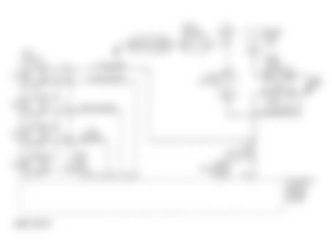
Isuzu Rodeo LS 1996 - Circuit Description
The PCM opens fuel injectors by grounding an injector driver circuit. PCM monitors voltage on each driver to detect a fault. If the voltage is not what the PCM expects to monitor, do to an injector driver being shorted to voltage for example, a DTC will be set.
Conditions required to set code are:
- Battery voltage is above 9 volts
- When injector is commanded off, injector voltage is not equal ignition voltage.
- When injector is commanded on, injector voltage does not equal zero volts.
- Above conditions met for 15 seconds.
Isuzu Rodeo LS 1996 - Diagnostic Procedures
- Perform On-Board (OBD) System Check. Read and record FREEZE FRAME and/or FAIL RECORDS data for each DTC set. Go to next step.
- Attempt to start engine. If engine starts, go to next step. If engine does not start, see ENGINE CRANKS BUT WILL NOT RUN in BASIC TESTING - 2.6L 4-CYL article.
- Using scan tool, clear DTCs. Run engine for one minute and check scan tool. If DTC P0201 has reset, go to step 5). If DTC P0201 has not set, go to next step.
- Turn ignition on with engine off. Using scan tool read FREEZE FRAME DATA and note parameters. Start engine and operate vehicle within FREEZE FRAME conditions. If DTC P0201 is reset, go to next step. If no DTC is set, go to DIAGNOSTIC AIDS.
- Turn engine off. Connect an injector test light to injector harness connector. Disable secondary ignition system to prevent engine from starting, and crank engine. If test light blinks, go to INJECTOR COIL TEST in SYSTEM & COMPONENT TESTING. If test light does not blink, go to next step.
- If test light was on steady in previous step, go to next step. If test light was not on steady in previous step, go to step 10).
- Disconnect PCM connector from affected injectors. Using test light connected to battery positive, probe affected injectors driver circuit at harness connector. If test light illuminates, go to next step. If test light does not illuminate, go to step 9).
- Replace short to ground in injector driver circuit and go to step 17).
- Replace PCM. Program replacement PCM using required equipment.
- Disconnect harness connector from fuel injector. Connect test light to chassis ground and probe ignition feed circuit of affected connector. Crank engine. If test light illuminates while cranking, go to next step. If test light does not illuminates, go to step 12).
- With test light still connected to ground, probe injector drive circuit of affected connector. Crank engine. If test light is on while cranking, go to step 14). If test light is not on while cranking, go to step 13).
- Repair open circuit in ignition feed circuit in injector harness and go to step 17).
- If an open is found in injector driver circuit, go to step 15). If no problem was found, go to step 16).
- Repair short to voltage in injector driver circuit and go to step 17).
- Repair open in injector drive circuit and go to step 17).
- Replace PCM. Program replacement PCM using required equipment.
- Using scan tool, read and record FAIL RECORDS DATA, and clear DTCs. Operate vehicle within conditions noted in FAIL RECORDS data. Using scan tool, select SPECIFIC DTC INFO for DTC P0201. If scan tool displays DTC P0201 FAILED THIS IGN, return to step 2). If scan tool does not display DTC P0201 FAILED THIS IGN, repair is complete.
Isuzu Rodeo LS 1996 - Diagnostic Aids
An open or short in injector driver circuit, will cause a DTC P0201 to set and a misfire due to inoperative injector. This type of DTC will indicate which cylinder is inoperative. Long and short term fuel trims being excessively excessively high or low are a good indication that an injector is faulty.
Isuzu Rodeo LS 1996 - DTC P0202 - INJECTOR 2 CONTROL CIRCUIT
NOTE: For circuit reference, see Fig. 7 , Code P0201 schematic.
Isuzu Rodeo LS 1996 - Circuit Description
The PCM opens fuel injectors by grounding an injector driver circuit. PCM monitors voltage on each driver to detect a fault. If the voltage is not what the PCM expects to monitor, do to an injector driver being shorted to voltage for example, a DTC will be set.
Conditions required to set code are:
- Battery voltage is above 9 volts
- When injector is commanded off, injector voltage is not equal ignition voltage.
- When injector is commanded on, injector voltage does not equal zero volts.
- Above conditions met for 15 seconds.
Isuzu Rodeo LS 1996 - Diagnostic Procedures
- Perform On-Board (OBD) System Check. Read and record FREEZE FRAME and/or FAIL RECORDS data for each DTC set. Go to next step.
- Attempt to start engine. If engine starts, go to next step. If engine does not start, see ENGINE CRANKS BUT WILL NOT RUN in BASIC TESTING - 2.6L 4-CYL article.
- Using scan tool, clear DTCs. Run engine for one minute and check scan tool. If DTC P0202 has reset, go to step 5). If DTC P0202 has not set, go to next step.
- Turn ignition on with engine off. Using scan tool read FREEZE FRAME DATA and note parameters. Start engine and operate vehicle within FREEZE FRAME conditions. If DTC P0202 is reset, go to next step. If no DTC is set, go to DIAGNOSTIC AIDS.
- Turn engine off. Connect an injector test light to injector harness connector. Disable secondary ignition system to prevent engine from starting, and crank engine. If test light blinks, go to INJECTOR COIL TEST in SYSTEM & COMPONENT TESTING. If test light does not blink, go to next step.
- If test light was on steady in previous step, go to next step. If test light was not on steady in previous step, go to step 10).
- Disconnect PCM connector from affected injectors. Using test light connected to battery positive, probe affected injectors driver circuit at harness connector. If test light illuminates, go to next step. If test light does not illuminate, go to step 9).
- Replace short to ground in injector driver circuit and go to step 17).
- Replace PCM. Program replacement PCM using required equipment.
- Disconnect harness connector from fuel injector. Connect test light to chassis ground and probe ignition feed circuit of affected connector. Crank engine. If test light illuminates while cranking, go to next step. If test light does not illuminates, go to step 12).
- With test light still connected to ground, probe injector drive circuit of affected connector. Crank engine. If test light is on while cranking, go to step 14). If test light is not on while cranking, go to step 13).
- Repair open circuit in ignition feed circuit in injector harness and go to step 17).
- If an open is found in injector driver circuit, go to step 15). If no problem was found, go to step 16).
- Repair short to voltage in injector driver circuit and go to step 17).
- Repair open in injector drive circuit and go to step 17).
- Replace PCM. Program replacement PCM using required equipment.
- Using scan tool, read and record FAIL RECORDS DATA, and clear DTCs. Operate vehicle within conditions noted in FAIL RECORDS data. Using scan tool, select SPECIFIC DTC INFO for DTC P0202. If scan tool displays DTC P0202 FAILED THIS IGN, return to step 2). If scan tool does not display DTC P0202 FAILED THIS IGN, repair is complete.
Isuzu Rodeo LS 1996 - Diagnostic Aids
An open or short in injector driver circuit, will cause a DTC P0202 to set and a misfire due to inoperative injector. This type of DTC will indicate which cylinder is inoperative. Long and short term fuel trims being excessively excessively high or low are a good indication that an injector is faulty.
Isuzu Rodeo LS 1996 - DTC P0203 - INJECTOR 3 CONTROL CIRCUIT
NOTE: For circuit reference, see Fig. 7 , Code P0201 schematic.
Isuzu Rodeo LS 1996 - Circuit Description
The PCM opens fuel injectors by grounding an injector driver circuit. PCM monitors voltage on each driver to detect a fault. If the voltage is not what the PCM expects to monitor, do to an injector driver being shorted to voltage for example, a DTC will be set.
Conditions required to set code are:
- Battery voltage is above 9 volts
- When injector is commanded off, injector voltage is not equal ignition voltage.
- When injector is commanded on, injector voltage does not equal zero volts.
- Above conditions met for 15 seconds.
Isuzu Rodeo LS 1996 - Diagnostic Procedures
- Perform On-Board (OBD) System Check. Read and record FREEZE FRAME and/or FAIL RECORDS data for each DTC set. Go to next step.
- Attempt to start engine. If engine starts, go to next step. If engine does not start, see ENGINE CRANKS BUT WILL NOT RUN in BASIC TESTING - 2.6L 4-CYL article.
- Using scan tool, clear DTCs. Run engine for one minute and check scan tool. If DTC P0203 has reset, go to step 5). If DTC P0203 has not set, go to next step.
- Turn ignition on with engine off. Using scan tool read FREEZE FRAME DATA and note parameters. Start engine and operate vehicle within FREEZE FRAME conditions. If DTC P0203 is reset, go to next step. If no DTC is set, go to DIAGNOSTIC AIDS.
- Turn engine off. Connect an injector test light to injector harness connector. Disable secondary ignition system to prevent engine from starting, and crank engine. If test light blinks, go to INJECTOR COIL TEST in SYSTEM & COMPONENT TESTING. If test light does not blink, go to next step.
- If test light was on steady in previous step, go to next step. If test light was not on steady in previous step, go to step 10).
- Disconnect PCM connector from affected injectors. Using test light connected to battery positive, probe affected injectors driver circuit at harness connector. If test light illuminates, go to next step. If test light does not illuminate, go to step 9).
- Replace short to ground in injector driver circuit and go to step 17).
- Replace PCM. Program replacement PCM using required equipment.
- Disconnect harness connector from fuel injector. Connect test light to chassis ground and probe ignition feed circuit of affected connector. Crank engine. If test light illuminates while cranking, go to next step. If test light does not illuminates, go to step 12).
- With test light still connected to ground, probe injector drive circuit of affected connector. Crank engine. If test light is on while cranking, go to step 14). If test light is not on while cranking, go to step 13).
- Repair open circuit in ignition feed circuit in injector harness and go to step 17),
- If an open is found in injector driver circuit, go to step 15). If no problem was found, go to step 16).
- Repair short to voltage in injector driver circuit and go to step 17).
- Repair open in injector drive circuit and go to step 17).
- Replace PCM. Program replacement PCM using required equipment.
- Using scan tool, read and record FAIL RECORDS DATA, and clear DTCs. Operate vehicle within conditions noted in FAIL RECORDS data. Using scan tool, select SPECIFIC DTC INFO for DTC P0203. If scan tool displays DTC P0203 FAILED THIS IGN, return to step 2). If scan tool does not display DTC P0203 FAILED THIS IGN, repair is complete.
Isuzu Rodeo LS 1996 - Diagnostic Aids
An open or short in injector driver circuit, will cause a DTC P0203 to set and a misfire due to inoperative injector. This type of DTC will indicate which cylinder is inoperative. Long and short term fuel trims being excessively excessively high or low are a good indication that an injector is faulty.
Isuzu Rodeo LS 1996 - DTC P0204 - INJECTOR 4 CONTROL CIRCUIT
NOTE: For circuit reference, see Fig. 7 , Code P0201 schematic.
Isuzu Rodeo LS 1996 - Circuit Description
The PCM opens fuel injectors by grounding an injector driver circuit. PCM monitors voltage on each driver to detect a fault. If the voltage is not what the PCM expects to monitor, do to an injector driver being shorted to voltage for example, a DTC will be set.
Conditions required to set code are:
- Battery voltage is above 9 volts.
- When injector is commanded off, injector voltage is not equal ignition voltage.
- When injector is commanded on, injector voltage does not equal zero volts.
- Above conditions met for 15 seconds.
Isuzu Rodeo LS 1996 - Diagnostic Procedures
- Perform On-Board (OBD) System Check. Read and record FREEZE FRAME and/or FAIL RECORDS data for each DTC set. Go to next step.
- Attempt to start engine. If engine starts, go to next step. If engine does not start, see ENGINE CRANKS BUT WILL NOT RUN in BASIC TESTING - 2.6L 4-CYL article.
- Using scan tool, clear DTCs. Run engine for one minute and check scan tool. If DTC P0204 has reset, go to step 5). If DTC P0204 has not set, go to next step.
- Turn ignition on with engine off. Using scan tool read FREEZE FRAME DATA and note parameters. Start engine and operate vehicle within FREEZE FRAME conditions. If DTC P0204 is reset, go to next step. If no DTC is set, go to DIAGNOSTIC AIDS.
- Turn engine off. Connect an injector test light to injector harness connector. Disable secondary ignition system to prevent engine from starting, and crank engine. If test light blinks, go to INJECTOR COIL TEST in SYSTEM & COMPONENT TESTING. If test light does not blink, go to next step.
- If test light was on steady in previous step, go to next step. If test light was not on steady in previous step, go to step 10).
- Disconnect PCM connector from affected injectors. Using test light connected to battery positive, probe affected injectors driver circuit at harness connector. If test light illuminates, go to next step. If test light does not illuminate, go to step 9).
- Replace short to ground in injector driver circuit and go to step 17).
- Replace PCM. Program replacement PCM using required equipment.
- Disconnect harness connector from fuel injector. Connect test light to chassis ground and probe ignition feed circuit of affected connector. Crank engine. If test light illuminates while cranking, go to next step. If test light does not illuminates, go to step 12).
- With test light still connected to ground, probe injector drive circuit of affected connector. Crank engine. If test light is on while cranking, go to step 14). If test light is not on while cranking, go to step 13).
- Repair open circuit in ignition feed circuit in injector harness and go to step 17).
- If an open is found in injector driver circuit, go to step 15). If no problem was found, go to step 16).
- Repair short to voltage in injector driver circuit and go to step 17).
- Repair open in injector drive circuit and go to step 17).
- Replace PCM. Program replacement PCM using required equipment.
- Using scan tool, read and record FAIL RECORDS DATA, and clear DTCs. Operate vehicle within conditions noted in FAIL RECORDS data. Using scan tool, select SPECIFIC DTC INFO for DTC P0204. If scan tool displays DTC P0204 FAILED THIS IGN, return to step 2). If scan tool does not display DTC P0204 FAILED THIS IGN, repair is complete.
Isuzu Rodeo LS 1996 - Diagnostic Aids
An open or short in injector driver circuit, will cause a DTC P0204 to set and a misfire due to inoperative injector. This type of DTC will indicate which cylinder is inoperative. Long and short term fuel trims being excessively excessively high or low are a good indication that an injector is faulty.
Isuzu Rodeo LS 1996 - DTC P0300 - ENGINE MISFIRE DETECTED Circuit Description
Misfire is detected using Camshaft Position (CMP) and Crankshaft Position (CKP) sensors. When PCM senses CKP deceleration not associated with normal engine speed reduction, CMP is used to determine misfiring cylinder. PCM determines misfires on each cylinder and evaluates a random misfire and set DTC.
Conditions required to set code are:
- No VSS DTCs set.
- No CKP, CMP, ECT, MAF, MAP or TP sensor DTCs set.
- Engine speed 600-6250 RPM.
- System voltage 11-16 volts.
- ECT 20-248?F (-7-120?C).
- Throttle steady.
- PCM detects crankshaft RPM variation, indicating a misfire which could cause catalytic convertor damage or high emissions.
Isuzu Rodeo LS 1996 - Diagnostic Procedures
- Perform On-Board (OBD) System Check. Read and record FREEZE FRAME and/or FAIL RECORDS data for each DTC set. Go to next step.
- Start engine and allow it to idle. Using scan tool, read and record FREEZE FRAME data. Operate vehicle within conditions noted in FREEZE FRAME data. Using scan tool, read MISFIRE CUR # display for each cylinder. If MISFIRE CUR # is increasing (indicating a misfire currently occurring) for any cylinder, go to next step. If MISFIRE CUR # is not increasing, go to DIAGNOSTIC AIDS.
- Check vacuum hoses for splits, kinks, or improper connections. If a problem is found, repair as necessary and go to step 18). If no problem is found, go to next step.
- Check intake manifold, injector "O" rings, EGR valve, and EGR feed pipes for vacuum leaks. If a problem is found, repair as necessary and go to step 18). If no problem is found, go to next step.
- Check PCV valve for improper installation or damaged hose. If a problem is found repair and go to step 18). If no problem is found, go to next step.
- Inspect interior of distributor cap for carbon tracking. Check distributor rotor for damage. If a problem is found repair as necessary and go to step 18). If no problem was found, go to next step.
- Remove ignition coil. Check ignition coil for cracks or carbon tracking. If a problem is found, replace damaged coil and go to step 18). If no problem is found, go to next step.
- Remove EGR valve and inspect valve, seat and passages for damage. Inspect valve pintle to ensure it is not sticking partially open. If a problem is found, repair as necessary and go to step 18). If no problem is found, go to next step.
- Install a spark tester on spark plug wire at spark plug end for cylinder indicating most severe misfire. Crank engine and check for crisp, Blue spark at tester. Repeat procedure for each affected cylinder. If spark is okay on all cylinders, go to step 14). If spark is not okay on any cylinder, go to next step.
- Remove spark plug(s) associated with misfiring cylinder(s). Check spark plugs for excessive fouling. If spark plugs are excessively fouled, diagnose and repair mechanical engine problem. If spark plugs are not excessively fouled, go to next step.
- Check spark plug insulation for cracks, carbon tracking or other damage. If a problem is found, replace faulty spark plug(s) and go to step 18). If no problem is found, go to next step.
- Replace ignition control module and go to next step.
- Check PCM injector, power and sensor grounds for clean and tight connection, and for proper location. If a problem is found, repair as necessary and go to step 18). If no problem is found, go to next step.
- Perform a FUEL PUMP PRESSURE TEST see BASIC DIAGNOSTIC PROCURERS. If a problem was found, repair as necessary and go to step 18). If no problem was found, go to next step.
- Check for fuel contamination. If fuel is contaminated, repair condition causing contamination and go to step 18). If fuel is okay, go to next step.
- Perform INJECTOR BALANCE TEST under FUEL SYSTEM in SYSTEM/COMPONENT TESTS - 2.6L 4-CYL article. If a problem is found, repair as necessary and go to step 18). If no problem is found, go to next step.
- Diagnose mechanical engine problems such as; faulty or incorrect camshaft, leaking valves or piston rings or sticky valves, excessive valve deposits, loose or worn rocker arms, weak valve springs, incorrect valve timing, leaking head gasket or loose or broken motor mounts. If a problem is found, repair as necessary and go to nest step.
- Using scan tool, read and record FREEZE FRAME data. Clear DTCs. Start engine and allow it to idle. Operate vehicle within conditions noted in FREEZE FRAME data. Using scan tool, read MISFIRE CUR # display for each cylinder. If MISFIRE CUR # is not increasing, repair is complete. If MISFIRE CUR # is increasing (indicating a misfire currently occurring) for any cylinder, return tostep 2).
Isuzu Rodeo LS 1996 - Diagnostic Aids
Check secondary ignition wires. Check for damaged or faulty ignition coil. Substitute a known-good ignition coil. Check system grounds. Check MAF sensor, air induction system, fuel pressure, injectors, and EGR valve.
Extended idle periods or short trip driving could leave deposits on HO2S. Deposits could cause HO2S to respond slowly, affecting fuel control and causing misfire at idle.
Isuzu Rodeo LS 1996 - DTC P0336 - CKP SENSOR CIRCUIT 58X REFERENCE SIGNAL
Fig. 8: Isuzu Rodeo LS 1996 - Component Locations - CKP Sensor Circuit (Rodeo 2.6L)

Isuzu Rodeo LS 1996 - Circuit Description
CKP produces 58X reference signal. PCM uses this information to calculate engine speed and CKP at engine speeds less than 1200 RPM. PCM compares number of 58X reference pulses to Camshaft Position (CMP) pulses. If PCM receives incorrect number of pulses, DTC P0336 will set.
Conditions required to set DTC are:
- Engine running.
- Extra or missing pulse is detected between consecutive 58X reference pulses.
- Listed conditions detected in 10 of 100 crankshaft rotations.
Isuzu Rodeo LS 1996 - Diagnostic Procedures
- Perform ON-Board Diagnostic (OBD) System Check. Read and record FREEZE FRAME and/or FAIL RECORDS data for each DTC set. Go to next step.
- Attempt to start engine. If engine starts and runs, go to next step. If engine does not start and run, see ENGINE DOES NOT START in BASIC TESTING - 2.6L 4-CYL article.
- Using scan tool, clear DTC P0336. Start engine and allow it to idle for one minute. Read DTCs. If DTC P0336 resets, go to next step. If DTC does not reset, go to DIAGNOSTIC AIDS.
- Disconnect PCM and CMP sensor connector. Check for an open or a short to ground in 58X reference circuit between CKP sensor connector and PCM harness connector. If a problem is found, repair as necessary and go to step 10. If no problem is found, go to next step.
- Reconnect PCM and CKP sensor. Using a DVOM measure voltage on 58X reference circuit at PCM connector while cranking engine. If DVOM reads around 2.5 volts, go to step 8). If voltage is not as specified, go to next step.
- Check for faulty connections at CKP sensor. If a faulty connection is found, repair as necessary and go to step 10). If connections are okay, go to next step.
- Replace CKP sensor and go to step 10).
- Check for faulty connections at PCM. If a faulty connection is found, repair as necessary and go to step 10). If connections are okay, go to next step.
- Replace PCM. Program replacement PCM using required equipment. Go to next step.
- Read and record FAIL RECORDS data for DTC P0336. Operate vehicle within conditions noted in FAIL RECORDS data. Using scan tool, read SPECIFIC DTC. If scan tool displays DTC P0336 FAILED THIS IGN, return to step 2). If scan tool does not display DTC P0336 FAILED THIS IGN, repair is complete.
Isuzu Rodeo LS 1996 - Diagnostic Aids
Check for faulty connections or damaged harness. Observe a voltmeter connected to 58X CKP sensor reference circuit at PCM harness connector while moving all related harness and connectors. A change in voltage indicates fault location.
Isuzu Rodeo LS 1996 - DTC P0337 - CKP SENSOR CIRCUIT LOW FREQUENCY
NOTE: For circuit reference, see Fig. 8 , Code P0336 schematic.
Isuzu Rodeo LS 1996 - Circuit Description
CKP produces 58X reference signal. PCM uses this information to calculate engine speed and CKP at engine speeds less than 1200 RPM. PCM compares number of 58X reference pulses to Camshaft Position (CMP) pulses. If PCM receives incorrect number of pulses, DTC P0337 will set.
Conditions required to set DTC are:
- Engine cranking.
- No CMP sensor DTCs are set.
- CKP sensor signal is not present between two cam pulses.
- CKP reference pule is not detected within 8 CMP pulses.
Isuzu Rodeo LS 1996 - Diagnostic Procedures
- Perform ON-Board Diagnostic (OBD) System Check. Read and record FREEZE FRAME and/or FAIL RECORDS data for each DTC set. Go to next step.
- Attempt to start engine. If engine starts and runs, go to next step. If engine does not start and run, see ENGINE DOES NOT START in BASIC TESTING - 2.6L 4-CYL article.
- Using scan tool, clear DTC P0337. Start engine and allow it to idle for one minute. Read DTCs. If DTC P0337 resets, go to next step. If DTC does not reset, go to DIAGNOSTIC AIDS.
- Turn ignition off and disconnect CKP sensor. Turn ignition on. Connect DVOM between 5 volt reference and sensor ground terminals at connector harness. If DVOM reads 5 volts, go to step 7). If reading is not as specified, go to next step.
- With ignition on, use DVOM to backprobe PCM connector reference and ground terminals. If DVOM reads 5 volts, go to next step. If feeding is not as specified, go to step 11).
- Using DVOM, check resistance at reference and ground circuits at CKP harness connector. If an open or short is discovered, repair circuit and go to step 13).
- Turn ignition off and disconnect PCM and CKP sensor. Check for an open or a short in 58X reference circuit between CKP sensor connector and PCM harness connector. If a problem is found, repair as necessary and go to step 13). If no problem is found, go to next step.
- Connect PCM and CKP sensor. Using DVOM, measure voltage on 58X reference circuit at PCM connector and crank engine. If reading on DVOM is around 2.5 volts, go to step 11). If voltage is not as specified, go to next step.
- Inspect connections at CKP sensor. Repair connections as necessary and go to step 13). If connections did not require repair, go to next step.
- Replace CKP sensor and go to step 13).
- Inspect connections at PCM. Repair connections as necessary and go to step 13). If connections did not require repair, go to next step.
- Replace PCM and go to next step.
- Read and record FAIL RECORDS data for DTC P0337. Operate vehicle within conditions noted in FAIL RECORDS data. Using scan tool, read SPECIFIC DTC. If scan tool displays DTC P0337 FAILED THIS IGN, return to step 2). If scan tool does not display DTC P0337 FAILED THIS IGN, repair is complete.
Isuzu Rodeo LS 1996 - Diagnostic Aids
Check for faulty connections or damaged harness. Observe a voltmeter connected to 58X CKP sensor reference circuit at PCM harness connector while moving all related harness and connectors. A change in voltage indicates fault location.
Isuzu Rodeo LS 1996 - DTC P0341 - CAMSHAFT POSITION SENSOR CIRCUIT
NOTE: For circuit reference, see Fig. 8 , Code P0336 schematic.
Isuzu Rodeo LS 1996 - Circuit Description
DTC P0341 will set if Camshaft Position (CMP) sensor pulses are not in proper ratio to 58X reference pulses.
Conditions required to set DTC are:
- Engine running and PCM receiving reference pulses.
- Above condition fails for 100 occurrences within 200 test samples.
Isuzu Rodeo LS 1996 - Diagnostic Procedures
- Perform On-Board Diagnostic (OBD) System Check. Read and record FREEZE FRAME and/or FAIL RECORDS data for each DTC set. Go to next step.
- Turn ignition on. Using scan tool, read and record FAIL RECORDS data for DTC P0341. Operate vehicle within conditions noted in FAIL RECORDS data. Using scan tool, read SPECIFIC DTC. If scan tool displays DTC P0341 FAILED THIS IGN, go to next step. If scan tool does not display DTC P0341 FAILED THIS IGN, see DIAGNOSTIC AIDS.
- Disconnect CMP sensor. Measure voltage at CMP sensor harness connector. between senor feed circuit and sensor ground circuit. If DVOM reading is around 5-6 volts, go to next step. If reading is not as specified, go to step 5).
- Measure voltage between CMP sensor signal circuit and sensor ground circuit at CMP sensor harness connector. If reading is around 5-7 volts, got to step 11). If reading is not as specified, go to step 8).
- If voltage measured in step 3 was less then 5-6 volts, go to next step. If voltage in step 3 was greater than 5-6 volts, repair short to voltage in CMP supply circuit and go to step 16).
- Inspect CMP sensor for poor connections. If a problem, was found, repair problem as necessary and go to step 16). If no problem was found, go to next step.
- With ignition off, disconnect PCM and CMP sensor. Inspect sensor feed circuits for an open between ignition control module and CMP sensor. If a problem was found, repair as necessary and go tostep 16). If no problem was found, go to step 9).
- With ignition off, disconnect PCM and leave CMP sensor disconnected. Turn ignition on and check CMP sensor signal circuit for an open or a short to voltage and check CMP sensor input signal circuit for a short to ground. If a problem was found, repair as necessary and go to step 16). If no problem was found, go to next step.
- Check for open or short in CMP sensor ground circuit. If a problem is found, repair as necessary and go to step 16). If no problem is found, go to next step.
- Check for poor connection at PCM. If a problem is found, repair as necessary and go to step 16). If no open is found, go to next step.
- Using DVOM backprobe sensor connector at CMP signal circuit. With sensor connected, crank engine and monitor voltage. If voltage toggle between 0-4 volts, go to step 15). If voltage does not toggle between 0-4 volts, go to next step.
- Leaving senor wiring connected, remove distributor cap front cover. Place a magnet on CMP senor face which normally faces magnet in distributor. Using DVOM measure voltage. If reading is not as specified, go to step 14). If voltage reads at around zero, got to next step.
- Replace faulty or missing magnet and go to step 16).
- Replace CMP sensor and go to step 16).
- Replace PCM. Program replacement PCM using required equipment. After repair is completed, go to next step.
- Read and record FAIL RECORDS data for DTC P0336. Operate vehicle within conditions noted in FAIL RECORDS data. Using scan tool, read SPECIFIC DTC. If scan tool displays DTC P0336 FAILED THIS IGN, return to step 2). If scan tool does not display DTC P0336 FAILED THIS IGN, repair is complete.
Isuzu Rodeo LS 1996 - Diagnostic Aids
Check for incorrect harness routing near secondary ignition components, ignition coil arcing to wiring harness or ICM. Check ignition coils for cracks, carbon tracking or other signs of damage. Check for secondary ignition wire(s) arcing to wiring harness.
Check for faulty connections or damaged harness. Observe a voltmeter connected to CMP sensor signal circuit at PCM harness connector while moving all related harness and connectors. A change in voltage indicates fault location.
Isuzu Rodeo LS 1996 - DTC P0342 - CAMSHAFT POSITION SENSOR CIRCUIT LOW
NOTE: For circuit reference, see Fig. 8 , Code P0336 schematic.
Isuzu Rodeo LS 1996 - Circuit Description
DTC P0341 will set if Camshaft Position (CMP) sensor pulses are not in proper ratio to 58X reference pulses.
Conditions required to set DTC are:
- Engine running.
- PCM not receiving reference pulses from CMP once every 4 cylinders.
- Above condition occurs for 10 seconds.
Isuzu Rodeo LS 1996 - Diagnostic Procedures
- Perform On-Board Diagnostic (OBD) System Check. Read and record FREEZE FRAME and/or FAIL RECORDS data for each DTC set. Go to next step.
- Turn ignition on. Using scan tool, read and record FAIL RECORDS data for DTC P0341. Operate vehicle within conditions noted in FAIL RECORDS data. Using scan tool, read SPECIFIC DTC. If scan tool displays DTC P0342 FAILED THIS IGN, go to next step. If scan tool does not display DTC P0342 FAILED THIS IGN, see DIAGNOSTIC AIDS.
- Disconnect CMP sensor. Turn ignition on. Measure voltage at CMP sensor harness connector. between senor feed circuit and sensor ground circuit. If DVOM reading is around 5 volts, go to step 7) . If reading is not as specified, go to next.
- Turn ignition off. Disconnect PCM and CMP sensor and check for poor connections at CMP. If no problem is found, go to next step. If a problem is found, repair as necessary and go to step 16).
- Check for poor connection at PCM. If a problem is found, repair as necessary and go to step 16). If no open is found, go to next step.
- Inspect harness between PCM and CMP sensor for sensor feed circuit open or short to ground and sensor ground circuit open or short to voltage. If a problem is found, repair as necessary and go to step 16). If no problem is found, go to next step.
- Turn ignition on, engine off. Measure voltage between CMP sensor signal circuit and sensor ground circuit at CMP sensor harness connector. If reading is around 5-7 volts, got to next step. If reading is not as specified, go to step 9).
- Turn ignition off. Disconnect PCM and connect a DVOM to monitor voltage on CMP signal circuit at PCM connector. Turn ignition on. Monitor voltage display with DVOM while repeatedly touching CMP sensor signal circuit at CMP sensor connection with a test light to ground. If DVOM displays voltage toggling between 0 and 5 volts when test light is touched to CMP sensor signal circuit, go to step 12). If voltage does not toggle, go to next step.
- Leaving PCM disconnected, turn ignition on. Probe CMP signal circuit at PCM connector with a test light connected to battery positive. If test light illuminates, locate and repair short at ground in CMP signal circuit than go to step 16). If test light does not illuminate, go to next step.
- Leaving PCM disconnected and ignition on, probe CMP signal circuit with a test light connected to ground. If test light illuminates, locate and repair short to voltage in CMP signal circuit than go to step 16). If test light does not illuminate, go to next step.
- With ignition off, disconnect PCM and leave CMP sensor disconnected. Turn ignition of and check CMP sensor signal circuit for an open. If problem is found, repair as necessary and go to step 16).
- Remove distributor cap leaving sensor disconnected. Turn ignition on, place a magnet on CMP senor face which normally faces magnet in distributor. Using DVOM read voltage. If reading is near zero volts go to step 14). If voltage is not as specified, go to next step.
- Replace CMP sensor and go to step 16).
- Replace PCM. Program replacement PCM using required equipment. After repair is completed, go to step 16).
- Replace faulty or missing magnet and go to next step.
- Read and record FAIL RECORDS data for DTC P0336. Operate vehicle within conditions noted in FAIL RECORDS data. Using scan tool, read SPECIFIC DTC. If scan tool displays DTC P0336 FAILED THIS IGN, return to step 2). If scan tool does not display DTC P0336 FAILED THIS IGN, repair is complete.
Isuzu Rodeo LS 1996 - Diagnostic Aids
Check for incorrect harness routing near secondary ignition components, ignition coil arcing to wiring harness or ICM. Check ignition coils for cracks, carbon tracking or other signs of damage. Check for secondary ignition wire(s) arcing to wiring harness.
Check for faulty connections or damaged harness. Observe a voltmeter connected to CMP sensor signal circuit at PCM harness connector while moving all related harness and connectors. A change in voltage indicates fault location.
Isuzu Rodeo LS 1996 - DTC P0351 - IGNITION CONTROL CIRCUIT
Fig. 9: Isuzu Rodeo LS 1996 - Component Locations - Ignition Control Circuit (Rodeo 2.6L)

Isuzu Rodeo LS 1996 - Circuit Description
When the module receives a 5 volt signal from the PCM, it provides a ground path for the battery voltage supplied to the ignition primary coil . When the PCM turns off the 5 volts to the module, the module will remove the ground path of the ignition primary coil, causing the magnetic field produced by the coil to collapse. The PCM monitors the circuit and will set DTC P0351 if a problem in the ignition control circuit is detected.
Conditions required to set DTC are:
- Ignition is on.
- Output voltage is not equal to 5 volts when output is on.
- Output voltage is not equal to 0 volts when output is off.
- 20 test failures have occurred within 40 samples of continuous circuit monitoring.
Isuzu Rodeo LS 1996 - Diagnostic Procedures
- Perform On-Board Diagnostic (OBD) System Check. Read and record FREEZE FRAME and/or FAIL RECORDS data for each DTC set. Go to next step.
- Turn ignition on, engine off. Using scan tool, read and record FAIL RECORDS data for DTC P0351. Operate vehicle within conditions noted in FAIL RECORDS data. Using scan tool, read SPECIFIC DTC. If scan tool does not display DTC P0351 FAILED THIS IGN, go tostep 4). If scan tool displays DTC P0351 FAILED THIS IGN, go to next step.
- Check ignition control module for poor connection or damaged terminals. If a problem is found, repair as necessary and go to step 8). If no problem is found, go to next step.
- Check PCM connector for poor connection or damaged terminals. If a problem is found, repair as necessary and go to step 8). If no problem is found, go to next step.
- Turn ignition off. Disconnect harness from PCM and ignition control module. Check ignition control circuit for an open, short to ground or voltage. If a problem is found, repair as necessary and go to step 8). If no problem is found, go to next step.
- Replace ignition control module and go to step 8).
- Replace PCM. Program replacement PCM using required equipment. After repair is completed, go to next step.
- Read and record FAIL RECORDS data for DTC P0351. Operate vehicle within conditions noted in FAIL RECORDS data. Using scan tool, read SPECIFIC DTC. If scan tool displays DTC P0351 FAILED THIS IGN, return to step 2). If scan tool does not display DTC P0351 FAILED THIS IGN, repair is complete.
Isuzu Rodeo LS 1996 - Diagnostic Aids
Check for poor PCM connection or damaged harness. Inspect wiring harness for damage by observing scan tool while moving connector and wiring related to ignition system. A change in display will indicate location of fault.
Isuzu Rodeo LS 1996 - DTC P0401 - EGR SYSTEM INSUFFICIENT FLOW Circuit Description
PCM tests Exhaust Gas Recirculation (EGR) valve during deceleration by momentarily commanding EGR valve on while monitoring engine MAP. PCM will illuminate MIL and store DTC P0401 if expected increase in MAP is not seen under certain conditions during deceleration.
Conditions required to set DTC are:
- No CKP, ECT, EGR pintle position, IAT, MAP, or TP sensor DTCs set.
- No misfire or VSS DTCs set.
- BARO is greater than 70 kPa.
- ECT greater than 140?F (60?C).
- IAC position steady, changing less than 10 counts..
- TCC status is unchanged.
- Vehicle speed greater than 15 MPH (24 km/h).
- Commanded state of A/C relay is steady.
Isuzu Rodeo LS 1996 - Diagnostic Procedures
- Perform On-Board Diagnostic (OBD) System Check. Read and record FREEZE FRAME and/or FAIL RECORDS data for each DTC set. Go to next step.
- If DTC P1406 is also set, go to DTC P1406. If DTC P1406 is not set, go to next step.
- Inspect exhaust system for modifications or leaks. If a problem is found, repair as necessary and go to step 6). If no problem is found, go to next step.
- Remove EGR valve and check pintle, valve and passages and adapter for excessive deposits or restriction. Check EGR valve gasket and pipes for leaks. If a problem is found, repair as necessary and go to step 6). If no problem is found, go to next step.
- Remove EGR inlet and outlet pipes from exhaust and intake manifolds. Inspect manifold EGR ports and pipes for blockage or damage. If a problem is found, repair as necessary and go to next step. If no problem is found, see DIAGNOSTIC AIDS.
- Read and record FAIL RECORDS data for DTC P0401. Clear DTCs and monitor EGR TEST COUNT while operating vehicle within conditions noted in DIAGNOSTIC AIDS until 9-12 test samples have been taken. Read SPECIFIC DTC. If scan tool displays DTC P0401 TEST RAN AND PASSED, repair is complete. If scan tool does not display DTC P0401 TEST RAN AND PASSED, return to step 2).
Isuzu Rodeo LS 1996 - Diagnostic Aids
PCM will only run EGR flow test during gradual deceleration, a closed throttle condition and with vehicle speed greater than 20 MPH. Accelerate vehicle to greater than 20 MPH, and gradually decelerate 9-13 times.
Check for faulty connections or damaged harness. Inspect PCM harness connector EGR control circuit for backed-out terminal. Observe ACTUAL EGR POSITION display on scan tool while moving all related harness and connectors. A change in scan tool display indicates fault location.
If EGR valve shows signs of excessive heat, check exhaust system for blockage or plugged catalytic converter.
Isuzu Rodeo LS 1996 - DTC P0420 - TWC SYSTEM LOW EFFICIENCY Circuit Description
Three-Way Catalyst (TWC) system is used to control emission. PCM uses signal from Heated Oxygen Sensors (HO2S) to read efficiency of TWC. PCM will set DTC P0420 if TWC oxygen storage capacity is less than a predetermined threshold.
Conditions required to set DTC are:
- No CKP, ECT, HO2S, IAT, MAF, MAP, or TP sensor DTCs set.
- No EGR pintle position, EVAP purge, fuel trim, injector circuit, misfire or VSS DTCs set.
- Engine is operating in closed loop.
- Engine air load in below 99 percent.
- ECT is above 140?F (60?C).
- MAF is between 8-50 grams/second.
- Change in engine load is below eight percent.
- TWC temperature is above 750?F (399?C).
- Engine speed below 3500 RPM.
- Vehicle speed 16-75 MPH (26-123 km/h).
- PCM determines TWC oxygen storage capacity less than predetermined threshold.
Isuzu Rodeo LS 1996 - Diagnostic Procedures
- Perform On-Board Diagnostic (OBD) System Check. Read and record FREEZE FRAME and/or FAIL RECORDS data for each DTC set. Go to next step.
- Diagnose any other DTCs before proceeding. If no other DTCs are set, go to next step.
- Ensure TWC is an original equipment part. Check TWC for dents or discoloration caused by excessive heat. Ensure no internal damaged catalyst rattle exists. If a problem is found, repair as necessary and go to step 6). If no problems are found, go to next step.
- Check exhaust system for leaks, damage, loose or missing hardware. If a problem is found, repair as necessary and go to step 7). If no problems are found, go to next step.
- Ensure HO2S 2 is securely installed and that harness is not damaged or contacting exhaust. If a problem is found, repair as necessary and go to step 7). If no problems are found, go to next step.
- Replace TWC. Check for possible engine misfire DTC or engine mechanical problem, and go to next step.
- Read and record FAIL RECORDS data for DTC P0401. Clear DTCs. Start engine and allow it to reach 167?F (75?C). Run engine while monitoring scan tool IAC RPM control function to maintain MAF at 12-15 grams per second for at least 2 minutes. Using scan tool, monitor TWC MONITOR TEST COUNTER while operating vehicle within conditions required to set DTC. Continue operating vehicle until TWC MONITOR TEST COUNTER reaches 49 and returns to zero 2 times. Read SPECIFIC DTC. If scan tool displays DTC P0420 TEST RAN AND PASSED, repair is complete. If scan tool does not display DTC P0420 TEST RAN AND PASSED, return to step 2).
Isuzu Rodeo LS 1996 - Diagnostic Aids
Check for faulty connections or damaged harness. Inspect PCM harness connector EGR control circuit for backed-out terminal. Observe scan tool while moving all related harness and connectors. A change in scan tool display indicates fault location.
Ensure engine has reached operating temperature. Place gear selector in Park. Using scan tool, monitor HO2S 1 and HO2S 2 values while using scan tool IAC RPM function to maintain MAF at 10 grams per second. Compare activity between HO2S 1 and HO2S 2 for 30 seconds. If activity between both HO2S is about equal, a problem exists. Repeat DTC P0420.
Isuzu Rodeo LS 1996 - DTC P0441 - EVAP SYSTEM NO FLOW DURING PURGE
Fig. 10: Isuzu Rodeo LS 1996 - Component Locations - EVAP Circuit (Rodeo 2.6L)

Isuzu Rodeo LS 1996 - Circuit Description
Evaporative (EVAP) emission canister purge is controlled by a solenoid valve which allows ported vacuum to purge canister when energized by PCM. A vacuum switch in purge line is used to detect when system is being purged. PCM supplies and reads a 5-volt reference to switch. If switch is closed (no purge detected) when commanded by PCM, DTC P0441 is set.
Conditions required to set DTC are:
- No ECT, IAT, MAF, MAP, TP sensor DTCs set.
- BARO greater than 70 kPa.
- Start-up IAT and ECT greater than 41?F (5?C).
- ECT below 158?F (70?C)
- Difference between ECT and IAT less than 45?F (25?C).
- Battery voltage between 11-16 volts.
- Engine speed above 800 RPM.
- TP angle above 13%.
- Canister purge duty cycle is above 95 percent.
- EVAP vacuum switch remains closed (12-volt signal at PCM) for three seconds.
Isuzu Rodeo LS 1996 - Diagnostic Procedures
- Perform On-Board Diagnostic (OBD) System Check. Read and record FREEZE FRAME and/or FAIL RECORDS data for each DTC set. Go to next step.
- Turn engine on and allow it to idle. Using scan tool, command EVAP purge solenoid on, while monitoring EVAP VACUUM SW on ENG 2 data list. If scan tool displays PURGE, go to next step. If scan tool does not display PURGE, go to step 4).
- Turn ignition on, engine off. Using scan tool, read and record FAIL RECORDS data for DTC P0441. Operate vehicle within conditions noted in FAIL RECORDS data. Using scan tool, read SPECIFIC DTC. If scan tool displays DTC P0441 FAILED THIS IGN, go to next step. If scan tool does not display DTC P0441 FAILED THIS IGN, see DIAGNOSTIC AIDS.
- Plug vacuum line between EVAP purge canister and EVAP vacuum switch. Turn engine on and allow it to idle. Using scan tool, command EVAP purge solenoid on, while monitoring EVAP VACUUM SW onENG 2 data list. If scan tool displays PURGE, go to next step. If scan tool does not display PURGE, go to step 6).
- Check vacuum line to canister for damage or improper connections. If a problem is found, repair as necessary and go to step 20). If no problem is found, go to step 14).
- Turn ignition off. Connect a vacuum gauge between EVAP purge solenoid and vacuum switch. Start engine and allow it to idle. Using scan tool, command EVAP purge solenoid on. If vacuum is not present, go to step 8). If vacuum gauge indicates vacuum, go to next step.
- Turn ignition off. Disconnect vacuum switch harness connector. turn ignition on. Observe EVAP VACUUM SW. If scan tool displays PURGE, go to step 15). If scan tool does not display PURGE, go to step 9).
- Turn ignition off. Connect a vacuum gauge to EVAP purge solenoid vacuum source. Start engine and allow it to idle. If vacuum gauge reads 5 in. of H2O, go to step 10). If vacuum is not as specified, go to step 16).
- Turn ignition off. Disconnect PCM connectors. Turn ignition on. Check for short to voltage in EVAP vacuum switch input circuit. If a problem is found, repair as necessary and go to step 20). If no problem is found, go to step 19).
- Turn ignition off. Disconnect EVAP purge solenoid harness connector. Connect a test light across EVAP purge solenoid harness connector signal and ground circuits. Turn ignition on. Using scan tool, command EVAP solenoid on. If test light does not illuminate, go to next step. If test light illuminates, go to step 17).
- Turn ignition off. Disconnect PCM connectors. Connect a test light across EVAP purge solenoid connector signal and ground circuits. Turn ignition on. Connect a jumper wire between EVAP purge solenoid connector driver circuit and PCM connector ground circuit. If test light does not illuminate, go to step 13). If test light illuminates, go to next step.
- Check for faulty connection at PCM. If faulty connection is found, repair as necessary and go to step 20). If connection is okay, go to step 19)
- Repair EVAP purge solenoid ignition feed circuit for open or short to ground, or EVAP purge solenoid driver circuit for open and go to step 20).
- Replace EVAP canister and go to step 20).
- Replace EVAP vacuum switch and go to step 20).
- Locate and repair cause of no vacuum and go to step 20).
- Check for faulty connection at EVAP purge solenoid. If faulty connection is found, repair as necessary and go to step 20). If connection is okay, go to next step.
- Replace EVAP purge solenoid and go to step 20).
- Replace PCM. Program replacement PCM using required equipment. After repair is completed, go to next step.
- Read and record FAIL RECORDS data for DTC P0441. Clear DTCs. Operate vehicle within conditions noted in FAIL RECORDS data. Using scan tool, read SPECIFIC DTC. If scan tool displays DTC P0441 FAILED THIS IGN, return to step 2). If scan tool does not display DTC P0441 FAILED THIS IGN, repair is complete.
Isuzu Rodeo LS 1996 - Diagnostic Aids
Check vacuum canister and hoses for damage. Check for faulty connections or damaged harness. Observe EVAP VACUUM SW display on scan tool while moving all related harness and connectors. A change in scan tool display indicates fault location.
Isuzu Rodeo LS 1996 - DTC P0502 - VSS CIRCUIT LOW INPUT
Fig. 11: Isuzu Rodeo LS 1996 - Component Locations - VSS Circuit (Rodeo 2.6L)

Isuzu Rodeo LS 1996 - Circuit Description
The VSS circuit uses a hall effect switch to inform the PCM of vehicle speed.
Conditions required to set DTC are:
- Engine is running.
- ECT is above 140?F (60?C).
- Engine speed is between 1800-2500 RPM.
- Throttle angle is between 10-100 percent.
- Engine load is greater than 50 kPa.
- PCM detects no VSS signal for 125 seconds over a period of 25 seconds.
Isuzu Rodeo LS 1996 - Diagnostic Procedures
- Perform On-Board Diagnostic (OBD) System Check. Read and record FREEZE FRAME and/or FAIL RECORDS data for each DTC set. Go to next step.
- Check speedometer. If speedometer works, go to step 11). If speedometer does not work, go to next step.
- Disconnect VSS harness connector and turn ignition on (with engine off). Connect a test light to positive battery post. Probe VSS connector ground terminal. If test light illuminates, go to step 5). If test light does not illuminate, go to next step.
- Repair sensor ground and go to step 16).
- With sensor disconnected, turn ignition on. Using DVOM, probe VSS connectors ground and voltage supply. If battery voltage is not displayed on DVOM, go to next step. If battery voltage is displayed, go to step 7).
- Repair open or short to ground which may have blown meter fuse and go to step 16).
- With sensor disconnected, turn ignition on. Using DVOM, probe VSS connectors ground and speedometer wire. If DVOM reads 7.5-8 volts, go to step 9). If reading is not as specified, go to next step.
- Repair open or short circuit between speedometer and VSS. Go to step 16).
- Raise and support rear of vehicle. Reconnect VSS harness connector. Using DVOM backprobe terminal containing wire form speedometer and chassis ground. Turn ignition on, with engine off and place transmission in neutral. Rotating rear wheels by hand, observe DVOM readings. If readings are not as specified, go to next step. If readings toggle between .6 volts and 10 volts, go to step 11).
- Replace VSS and go to step 16).
- With vehicle still in neutral, suspended above ground and ignition on, use scan tool to monitor VSS data while turning rear wheels by hand. If scan tool reads vehicle speed, go to step 13). If scan tool does not read vehicle speed, go to next step.
- Repair open or short between PCM and speedometer, speedometer ground, faulty meter circuit board or faulty speedometer. Go to step 16).
- Turn ignition off. Disconnect PCM and turn ignition back on. Using DVOM backprobe PCM connector. If DVOM reads near 9.4 volts, go to step 15). If voltage is not as specified, go to next step.
- Check for poor PCM connector or damaged terminal. Repair as necessary and go to step 16).
- Replace PCM. Program replacement PCM using required equipment. After repair is completed, go to next step.
- Read and record FAIL RECORDS data for DTC P0441. Clear DTCs. Operate vehicle within conditions noted in FAIL RECORDS data. Using scan tool, read SPECIFIC DTC. If scan tool displays DTC P0441 FAILED THIS IGN, return to step 2). If scan tool does not display DTC P0441 FAILED THIS IGN, repair is complete.
Isuzu Rodeo LS 1996 - DTC P0506 - IAC SYSTEM RPM LOW
Fig. 12: Isuzu Rodeo LS 1996 - Component Locations - IAC Circuit (Rodeo 2.6L)

Isuzu Rodeo LS 1996 - Circuit Description
PCM controls idle speed with an Idle Air Control (IAC) valve to a calculated RPM based on sensor inputs and actual engine RPM. PCM moves IAC valve in or out to vary amount of airflow into intake manifold and thus decrease or increase idle RPM.
PCM commands IAC in counts. A higher count, allows more air to bypass throttle plate (higher idle).
Conditions required to set DTC are:
- No CKP, ECT, IAT, MAF, MAP, TP or VSS sensor DTCs set.
- No EVAP solenoid, EVAP system, fuel trim, fuel injector or EGR pintle position DTCs set.
- BARO greater than 75 kPa
- Ignition voltage 9.5-16.7 volts.
- ECT greater than 122?F (50?C).
- Canister purge duty cycle is above 10 percent.
- Throttle closed.
- Engine speed greater than 180-200 RPM lower than desired idle.
- Listed conditions met for greater than 5 seconds.
Isuzu Rodeo LS 1996 - Diagnostic Procedures
- Perform On-Board Diagnostic (OBD) System Check. Read and record FREEZE FRAME and/or FAIL RECORDS data for each DTC set. Go to next step.
- Using scan tool, read DTCs. If any other DTCs are set, diagnose affected DTCs before proceeding. If no other DTCs are set, go to next step.
- Start engine. Turn all accessories off. Using scan tool, monitor ENGINE SPEED and command engine speed up to 1500 RPM, down to 650 RPM, and up to 1500 RPM. If ENGINE SPEED remains within 50 RPM of desired RPM for each command, see DIAGNOSTIC AIDS. If ENGINE SPEED is not as specified, to next step.
- Disconnect IAC harness connector. Install IAC Node Light (J37027 or equivalent) in IAC harness connector. With engine running, monitor node lights while commanding engine speed up to 1500 RPM, down to 500 RPM, and up to 1500 RPM. Both node lights should cycle Green and Red, but not OFF as RPM changes from 500-1500 RPM. If lights flash as specified, go to step 6). If lights do not flash as specified, go to next step.
- Check IAC "A" high and low, and "B" high and low circuits for open, short to voltage or short to ground. If a problem is found, repair as necessary and go to step 10). If no problem is found, go to step 9).
- Ensure throttle stop screw has not been tampered with. Check for stuck IAC valve or throttle linkage. Check for restrictions, collapse or blockage in air intake system, air ducts or air filter. Check throttle body bore and IAC for excessive deposits. If a problem is found, repair as necessary and go to step 10). If no problem is found, go to next step.
- Check for faulty connection at IAC harness connector. If faulty connection is found, repair as necessary and go to step 10). If connection is okay, go to next step.
- Replace IAC valve and go to step 11).
- Replace PCM. Program replacement PCM using required equipment. After repair is completed, go to next step.
- Start engine. Turn all accessories off. Using scan tool, monitor ENGINE SPEED and command engine speed up to 1500 RPM, down to 500 RPM, and up to 1500 RPM. If ENGINE SPEED remains within 50 RPM of desired RPM for each command, repair is complete. If ENGINE SPEED is not as specified, return to step 2).
Isuzu Rodeo LS 1996 - Diagnostic Aids
Check for faulty connection at IAC and PCM connectors. Check for damaged harness. Check for restrictions, collapse or blockage in air intake system, air ducts or air filter. Check throttle body bore and IAC for excessive deposits. Check for large vacuum leak, such as incorrectly installed PCV valve or disconnected brake booster hose. Check for restricted air intake system.
Isuzu Rodeo LS 1996 - DTC P0507 - IAC SYSTEM RPM HIGH
NOTE: For circuit reference, see Fig. 12 , Code P0506 schematic.
Isuzu Rodeo LS 1996 - Circuit Description
PCM controls idle speed with an Idle Air Control (IAC) valve to a calculated RPM based on sensor inputs and actual engine RPM. PCM moves IAC valve in or out to vary amount of airflow into intake manifold and thus decrease or increase idle RPM.
PCM commands IAC in counts. A higher count, allows more air to bypass throttle plate (higher idle).
Conditions required to set DTC are:
- No CKP, ECT, IAT, MAF, MAP, TP or VS sensor DTCs set.
- No EVAP solenoid, EVAP system, fuel trim, fuel injector or EGR pintle position DTCs set.
- BARO more than 75 kPa.
- Canister purge duty cycle is above 10 percent.
- Ignition voltage 9.5-16.7 volts.
- ECT more than 122?F (50?C).
- Engine running more than 125 seconds.
- Throttle closed.
- Engine speed more than 180-200 RPM lower than desired idle.
- Listed conditions met for 5 seconds.
Isuzu Rodeo LS 1996 - Diagnostic Procedures
- Perform ON-Board Diagnostic (OBD) System Check. Read and record FREEZE FRAME and/or FAIL RECORDS data for each DTC set. Go to next step.
- Using scan tool, read DTCs. If any other DTCs are set, diagnose affected DTCs before proceeding. If no other DTCs are set, go to next step.
- Start engine. Turn all accessories off. Using scan tool, monitor ENGINE SPEED and command engine speed up to 1500 RPM, down to 500 RPM, and up to 1500 RPM. If ENGINE SPEED remains within 50 RPM of desired RPM for each command, go to DIAGNOSTIC AIDS. If ENGINE SPEED is not as specified, to next step.
- Disconnect IAC harness connector. Install IAC Noid-light (J37027) in IAC harness connector. Monitor node lights while commanding engine speed up to 1500 RPM, down to 500 RPM, and up to 1500 RPM. Both node lights should cycle Green and Red, but not OFF as RPM changes from 500-1500 RPM. If lights flash as specified, go to step 6). If lights do not flash as specified, go to next step.
- Check IAC "A" high and low, and "B" high and low circuits for open, short to voltage or short to ground. If a problem is found, repair as necessary and go to step 10). If no problem is found, go to step 9).
- Check for vacuum leaks. Ensure throttle stop screw has not been tampered with. Check for throttle plate or shaft binding. Check accelerator and speed control cables for misadjustment or binding. Check for faulty, missing or incorrectly installed PCV valve. If a problem is found, repair as necessary and go to 10). If no problem is found, go to next step.
- Check for faulty connection at IAC harness connector. If faulty connection is found, repair as necessary and go to step 10). If connection is okay, go to next step.
- Replace IAC valve and go to step 10).
- Replace PCM. Program replacement PCM using required equipment. Go to next step.
- Start engine. Turn all accessories off. Using scan tool, monitor ENGINE SPEED and command engine speed up to 1500 RPM, down to 650 RPM, and up to 1500 RPM. If ENGINE SPEED remains within 50 RPM of desired RPM for each command, repair is complete. If ENGINE SPEED is not as specified, return to step 2).
Isuzu Rodeo LS 1996 - Diagnostic Aids
Check for faulty connection at IAC and PCM connectors. Check for damaged harness. Check for vacuum leaks. Check throttle body bore and IAC for excessive deposits. Check throttle plate for sticking.
Isuzu Rodeo LS 1996 - DTC P0562 - SYSTEM VOLTAGE LOW
Fig. 13: Isuzu Rodeo LS 1996 - Component Locations - PCM System Circuit (Rodeo 2.6L)
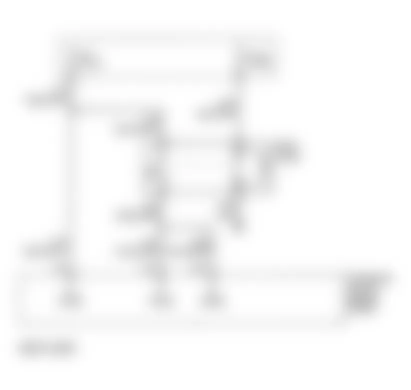
Isuzu Rodeo LS 1996 - Circuit Description
PCM monitors the system voltage of the ignition feed terminal to the PCM. A system voltage DTC will set whenever the voltage is below a calibrated value.
Conditions required to set DTC are:
- Ignition is on.
- System voltage is below 11.5 volts for 15 minutes.
Isuzu Rodeo LS 1996 - Diagnostic Procedures
- Perform On-Board Diagnostic (OBD) System Check. Read and record FREEZE FRAME and/or FAIL RECORDS data for each DTC set. Go to next step.
- Using DVOM, measure battery voltage at battery. If reading is greater than 11.5 volts, go to next step. If reading is 11.5 volts or less, charge battery before proceeding to next step.
- Install scan tool and select IGNITION VOLTS. Place vehicle in neutral or park. Start engine, raise engine speed to 2000 RPM and load electrical system (turn on headlights, blower, radio, etc.).If scan tool reads approximately 13.2 volts, go to next step. If reading is not as specified, see GENERATOR article in the ELECTRICAL article.
- Turn ignition off. Disconnect PCM connector. Turn ignition on, engine off. Using a DVOM, measure ignition voltage at PCM. If output is equal to battery voltage, check for excessive current draw with ignition off. If voltage is not equal to battery voltage, go to next step.
- Check for poor connections at PCM harness terminals. Repair as necessary and go to step 8). If no problem is found, go to next step.
- Check for an open ignition feed circuit to PCM. Repair as necessary and go to step 8). If no problem is found, go to next step.
- Replace PCM. Program replacement PCM using required equipment. Go to next step.
- Start engine. Turn all accessories off. Using scan tool, monitor ENGINE SPEED and command engine speed up to 1500 RPM, down to 650 RPM, and up to 1500 RPM. If ENGINE SPEED remains within 50 RPM of desired RPM for each command, repair is complete. If ENGINE SPEED is not as specified, return to step 2).
Isuzu Rodeo LS 1996 - Diagnostic Aids
If DTC sets when an accessory is operated, check for a poor connection or excessive current draw.
Isuzu Rodeo LS 1996 - DTC P0563 - SYSTEM VOLTAGE HIGH Circuit Description
PCM monitors the system voltage of the ignition feed terminal to the PCM. A system voltage DTC will set whenever the voltage is above a calibrated value.
Conditions required to set DTC are:
- Ignition is on.
- System voltage is above 16 volts for 15 minutes.
Isuzu Rodeo LS 1996 - Diagnostic Procedures
- Perform On-Board Diagnostic (OBD) System Check. Read and record FREEZE FRAME and/or FAIL RECORDS data for each DTC set. Go to next step.
- Using DVOM, measure battery voltage at battery. If reading is less than 11.5 volts, go to next step. If reading is 11.5 volts or more, go to step 4).
- Charge battery and clean battery, terminals and cable connections. If voltage is less than 11.5 volts, replace battery. If voltage is 11.5 volts or more, go next step.
- Turn all accessories off. Install scan tool and select ignition voltage parameter. Place vehicle in park or neutral. Start engine and raise engine speed to 2000 RPM. If scan tool reading is more than 14 volts, see GENERATOR article in the ELECTRICAL section. If voltage is not as specified, go to next step.
- Check for excessive current draw with ignition off. If excessive current draw present, go to DIAGNOSTIC AIDS. If no excessive current draw is present, go to next step.
- Replace PCM. Program replacement PCM using required equipment. Go to next step.
- Start engine. Turn all accessories off. Using scan tool, monitor ENGINE SPEED and command engine speed up to 1500 RPM, down to 650 RPM, and up to 1500 RPM. If ENGINE SPEED remains within 50 RPM of desired RPM for each command, repair is complete. If ENGINE SPEED is not as specified, return to step 2).
Isuzu Rodeo LS 1996 - Diagnostic Aids
If DTC sets when an accessory is operated, check for a poor connection or excessive current draw.
Isuzu Rodeo LS 1996 - DTC P0601 - PCM MEMORY Circuit Description
PCM uses an Electrically Erasable Programmable Read Only Memory (EEPROM). EEPROM contains program information and calibrations required for engine, transaxle, and powertrain diagnostics operation.
Condition required to set DTC is:
- PCM detects an internal program fault (check sum error).
Isuzu Rodeo LS 1996 - Diagnostic Procedures
- Perform On-Board Diagnostic (OBD) System Check. Read and record FREEZE FRAME and/or FAIL RECORDS data for each DTC set. Go to next step.
- Replace PCM. Program replacement PCM using required equipment. After repair is completed, repeat OBD system check.
Isuzu Rodeo LS 1996 - Diagnostic Aids
Only possible repair is replacement and programming of PCM.
Isuzu Rodeo LS 1996 - DTC P1106 - MAP SENSOR CIRCUIT INTERMITTENT HIGH VOLTAGE
NOTE: For circuit reference, see Fig. 1 , Code P0106 schematic.
Isuzu Rodeo LS 1996 - Circuit Description
Manifold Absolute Pressure (MAP) sensor measures changes in intake manifold pressure (vacuum). A low voltage signal, 2 volts, is sent to PCM on 5-volt reference circuit at closed throttle (high vacuum). A high voltage signal, 4 volts is sent at wide open throttle (low vacuum).
Conditions required to set DTC are:
- No TP sensor DTCs set.
- Engine is running.
- TP angle less than 3 percent, if engine speed is below 1000 RPM.
- TP angle less than 10 percent, if engine speed is above 1000 RPM.
- MAP sensor intermittently indicates MAP above 90 kPa for approximately 5 seconds over a 15-second period.
Isuzu Rodeo LS 1996 - Diagnostic Procedures
- Perform On-Board Diagnostic (OBD) System Check. Read and record FREEZE FRAME and/or FAIL RECORDS data for each DTC set. Go to next step.
- Using scan tool, select LAST TEST FAIL. Record any other failed DTCs. If DTC P0108 is also set, diagnose DTC P0108 before proceeding. If DTC is not set, go to next step.
- If DTC P1111, P1115, and/or P1121 is also set, go to step 6). If none of these DTCs are set, go to next step.
- Check for faulty sensor ground circuit terminal at MAP sensor. If problem is found, go to step 9). If no problem is found, go to next step.
- Check MAP signal circuit between MAP sensor harness connector and PCM for intermittent short to voltage. If a problem is found, go to step 10). If no problem is found, go to step 8).
- Check for intermittent short to voltage on 5-volt reference circuit between PCM and MAP, EGR and TP sensors. If a problem is found, go to step 10). If no problem is found, go to next step.
- Check for faulty ground circuit terminal connection at PCM. If problem is found, go to step 9). If no problem is found, go to next step.
- Check for intermittent open or faulty splice in sensor ground circuit. If a problem is found, go to step 10). If no problem is found, go to DIAGNOSTIC AIDS.
- Replace faulty connector terminal and go to step 11).
- Locate and repair intermittent open/short circuit and go to next step.
- Read and record FAIL RECORDS data for DTC P1106. Clear DTCs. Operate vehicle within conditions noted in FAIL RECORDS data. Using scan tool, read SPECIFIC DTC. If scan tool displays DTC P1106 FAILED THIS IGN, return to step 2). If scan tool does not display DTC P1106 FAILED THIS IGN, repair is complete.
Isuzu Rodeo LS 1996 - Diagnostic Aids
Check for faulty connections or damaged harness. Observe MAP display on scan tool while moving all related harness and connectors. A change in scan tool display indicates fault location.
Isuzu Rodeo LS 1996 - DTC P1107 - MAP SENSOR CIRCUIT INTERMITTENT LOW VOLTAGE
NOTE: For circuit reference, see Fig. 1 , Code P0106 schematic.
Isuzu Rodeo LS 1996 - Circuit Description
Manifold Absolute Pressure (MAP) sensor measures changes in intake manifold pressure (vacuum). A low voltage signal, 2 volts, is sent to PCM on 5-volt reference circuit at closed throttle (high vacuum). A high voltage signal, 4 volts is sent at wide open throttle (low vacuum).
Conditions required to set DTC are:
- No TP sensor DTCs set.
- Engine is running.
- TP ANGLE more than 1 percent with engine speed less than 1000 RPM.
- TP ANGLE more than 2 percent with engine speed more than 1000 RPM.
- MAP sensor intermittently indicates MAP below 11 kPa for approximately 5 seconds over a 16-second period.
Isuzu Rodeo LS 1996 - Diagnostic Procedures
- Perform On-Board Diagnostic (OBD) System Check. Read and record FREEZE FRAME and/or FAIL RECORDS data for each DTC set. Go to next step.
- Using scan tool, select LAST TEST FAIL. Record any other failed DTCs. If DTC P0107 is also set, diagnose DTC P0107 before proceeding. If DTC is not set, go to next step.
- If DTC P1122 is also set, go to step 6). If DTC is not set, go to next step.
- Check for faulty 5-volt reference or signal circuit connection at MAP sensor. If a problem is found, go to step 9). If no problem is found, go to next step.
- Check signal circuit between MAP sensor and PCM for intermittent open or short to ground. If problem is found, go to step 10). If no problem is found, go to step 8).
- Check for intermittent short to ground on 5-volt reference circuit between PCM and EGR valve, MAP and TP sensors. If a problem is found, go to step 10). If no problem is found, go to next step.
- Check for faulty 5-volt reference circuit connection at PCM. If faulty connection is found, go to step 9). If connection is okay, go to next step.
- Check for intermittent open or faulty splice in 5-volt reference circuit. If a problem is found, go to step 10). If no problem is found, go to DIAGNOSTIC AIDS.
- Replace faulty connector terminal(s) and go to step 11).
- Repair circuit as necessary and go to next step.
- Using scan tool, read and record FAIL RECORDS DATA, and clear DTCs. Operate vehicle within conditions noted in FAIL RECORDS data. Using scan tool, select SPECIFIC DTC INFO for DTC P1107. If scan tool displays DTC P1107 FAILED THIS IGN, return to step 2). If scan tool does not display DTC P1107 FAILED THIS IGN, repair is complete.
Isuzu Rodeo LS 1996 - Diagnostic Aids
Check for faulty connections or damaged harness. Observe MAP display on scan tool MAP while moving all related harness and connectors. A change in scan tool display indicates fault location.
Isuzu Rodeo LS 1996 - DTC P1111 - IAT SENSOR CIRCUIT INTERMITTENT HIGH VOLTAGE
NOTE: For circuit reference, see Fig. 2 , Code P0112 schematic.
Isuzu Rodeo LS 1996 - Circuit Description
Intake Air Temperature (IAT) sensor is a thermistor. PCM applies and reads a 5-volt reference signal to sensor. When air is cold, sensor resistance is high and PCM will measure a high signal voltage. If air is warm, sensor resistance is low causing PCM to measure low voltage.
Conditions required to set DTC are:
- No ECT, MAF or VSS sensor DTCs set.
- Vehicle speed less than 20 MPH (32 km/h).
- MAF less than 20 grams per second.
- ECT greater than 140?F (60?C).
- IAT signal voltage intermittently indicates IAT less than -38?F (-39?C) about 5 volts, for 2.5 seconds over a 25-second period.
Isuzu Rodeo LS 1996 - Diagnostic Procedures
- Perform On-Board Diagnostic (OBD) System Check. Read and record FREEZE FRAME and/or FAIL RECORDS data for each DTC set. Go to next step.
- Using scan tool, select LAST TEST FAIL. Record any other failed DTCs. If DTC P0113 is also set, diagnose DTC P0113 before proceeding. If DTC is not set, go to next step.
- If DTC P1106, P1115, and/or P1121 is also set, go to step 6). If none of these DTCs are set, go to next step.
- Check for faulty sensor ground circuit terminal at IAT sensor. If problem is found, repair as necessary and go to step 10). If no problem is found, go to next step.
- Check for faulty signal circuit connection at IAT sensor. If faulty connection is found, repair as necessary and go to step 10). If connection is okay, go to next step.
- Check IAT signal circuit between IAT sensor harness connector and PCM for intermittent open. If open is found, repair as necessary and go to step 10). If no open is found, go to next step.
- Check IAT signal circuit between IAT sensor harness connector and PCM for intermittent short to voltage. If short to voltage is found, repair as necessary and go to step 10). If no short to voltage is found, go to next step.
- Check for faulty ground circuit terminal connection at PCM. If problem is found, repair as necessary and go to step 10). If no problem is found, go to next step.
- Check for intermittent open or faulty splice in sensor ground circuit. If a problem is found, repair as necessary and go to next step. If no problem is found, see DIAGNOSTIC AIDS.
- Read and record FAIL RECORDS data for DTC P1111. Clear DTCs. Operate vehicle within conditions noted in FAIL RECORDS data. Using scan tool, read SPECIFIC DTC. If scan tool displays DTC P1111 FAILED THIS IGN, return to step 2). If scan tool does not display DTC P1111 FAILED THIS IGN, repair is complete.
Isuzu Rodeo LS 1996 - Diagnostic Aids
Check for faulty connections or damaged harness. Observe IAT display on scan tool while moving all related harness and connectors. A change in scan tool display indicates fault location. Check for skewed IAT sensor. See IAT TEMPERATURE-TO-RESISTANCE VALUES.
Isuzu Rodeo LS 1996 - DTC P1112 - IAT SENSOR CIRCUIT INTERMITTENT LOW VOLTAGE
NOTE: For circuit reference, see Fig. 2 , Code P0112 schematic.
Isuzu Rodeo LS 1996 - Circuit Description
Intake Air Temperature (IAT) sensor is a thermistor. PCM applies and reads a 5-volt reference signal to sensor. When air is cold, sensor resistance is high and PCM will measure a high signal voltage. If air is warm, sensor resistance is low causing PCM to measure low voltage.
Conditions required to set DTC are:
- No ECT, MAF, or VSS sensor DTCs set.
- Engine running longer than 2 minutes.
- Vehicle speed greater than 30 MPH (48 km/h).
- IAT signal voltage intermittently indicates IAT greater than 298?F (148?C) about .10 volts for 2.5 seconds over a 25-second period.
Isuzu Rodeo LS 1996 - Diagnostic Procedures
- Perform On-Board Diagnostic (OBD) System Check. Read and record FREEZE FRAME and/or FAIL RECORDS data for each DTC set. Go to next step.
- Using scan tool, select LAST TEST FAIL. Record any other failed DTCs. If DTC P0112 is also set, diagnose DTC P0112 before proceeding. If DTC is not set, go to next step.
- Check IAT signal circuit between IAT sensor harness connector and PCM for intermittent short to ground. If short to ground is found, repair as necessary and go to next step. If no short to ground is found, see DIAGNOSTIC AIDS.
- Read and record FAIL RECORDS data for DTC P1112. Clear DTCs. Operate vehicle within conditions noted in FAIL RECORDS data. Using scan tool, read SPECIFIC DTC. If scan tool displays DTC P1112 FAILED THIS IGN, return to step 2). If scan tool does not display DTC P1112 FAILED THIS IGN, repair is complete.
Isuzu Rodeo LS 1996 - Diagnostic Aids
Check for faulty connections or damaged harness. Observe IAT display on scan tool while moving all related harness and connectors. A change in scan tool display indicates fault location. Check for skewed IAT sensor. See IAT TEMPERATURE-TO-RESISTANCE VALUES.
Isuzu Rodeo LS 1996 - DTC P1114 - ECT SENSOR CIRCUIT INTERMITTENT LOW VOLTAGE
NOTE: For circuit reference, see Fig. 3 , Code P0117 schematic.
Isuzu Rodeo LS 1996 - Circuit Description
Engine Coolant Temperature (ECT) sensor is a thermistor or a variable resistor, that varies resistance based on temperature. As temperature of sensor increases, resistance decreases. High temperature will result in a low signal voltage. DTC will set when PCM sees an ECT sensor voltage intermittently less than 1.5 volt.
Condition required to set DTC is:
- Engine running for longer than 2 minutes.
- ECT sensor intermittently indicates ECT greater than 302?F (150?C)about .10 volts for 10 seconds over a 100-second period.
Isuzu Rodeo LS 1996 - Diagnostic Procedures
- Perform On-Board Diagnostic (OBD) System Check. Read and record FREEZE FRAME and/or FAIL RECORDS data for each DTC set. Go to next step.
- Using scan tool, select LAST TEST FAIL. Record any other failed DTCs. If DTC P0117 is also set, diagnose DTC P0117 before proceeding. If DTC is not set, go to next step.
- Check ECT signal circuit between ECT sensor harness connector and PCM for intermittent short to ground. If short to ground is found, repair as necessary and go to next step. If no short to ground is found, see DIAGNOSTIC AIDS.
- Read and record FAIL RECORDS data for DTC P1114. Clear DTCs. Operate vehicle within conditions noted in FAIL RECORDS data. Using scan tool, read SPECIFIC DTC. If scan tool displays DTC P1114 FAILED THIS IGN, return to step 2). If scan tool does not display DTC P1114 FAILED THIS IGN, repair is complete.
Isuzu Rodeo LS 1996 - Diagnostic Aids
Check for faulty connections or damaged harness. Observe ECT display on scan tool while moving all related harness and connectors. A change in scan tool display indicates fault location. Check for skewed ECT sensor. See ECT TEMPERATURE-TO-RESISTANCE VALUES.
Isuzu Rodeo LS 1996 - DTC P1115 - ECT SENSOR CIRCUIT INTERMITTENT HIGH VOLTAGE
NOTE: For circuit reference, see Fig. 3 , Code P0117 schematic.
Isuzu Rodeo LS 1996 - Circuit Description
Engine Coolant Temperature (ECT) sensor is a thermistor or a variable resistor, that varies resistance based on temperature. As temperature of sensor increases, resistance decreases. High temperature will result in a low signal voltage. DTC will set when PCM sees an ECT sensor voltage intermittently greater than 2 volts.
Conditions required to set DTC are:
- Engine running longer than 3 minutes.
- ECT sensor intermittently indicates ECT greater than -38?F (-39?C) about 5 volts for 10 seconds, over a 100-second period.
Isuzu Rodeo LS 1996 - Diagnostic Procedures
- Perform On-Board Diagnostic (OBD) System Check. Read and record FREEZE FRAME and/or FAIL RECORDS data for each DTC set. Go to next step.
- Using scan tool, select LAST TEST FAIL. Record any other failed DTCs. If DTC P0118 is also set, diagnose DTC P0118 before proceeding. If DTC is not set, go to next step.
- If DTC P1106, P1111, and/or P1121 is also set, go to step 8). If none of these DTCs are set, go to next step.
- Check for faulty sensor ground circuit terminal at ECT sensor. If problem is found, repair as necessary and go to step 10). If no problem is found, go to next step.
- Check for faulty signal circuit connection at ECT sensor. If faulty connection is found, repair as necessary and go to step 10). If connection is okay, go to next step.
- Check ECT signal circuit between ECT sensor harness connector and PCM for intermittent open. If open is found, repair as necessary and go to step 10). If no open is found, go to next step.
- Check ECT signal circuit between ECT sensor harness connector and PCM for intermittent short to voltage. If short to voltage is found, repair as necessary and go to step 10). If no short to voltage is found, go to next step.
- Check for faulty ground circuit terminal connection at PCM. If problem is found, repair as necessary and go to step 10). If no problem is found, go to next step.
- Check for intermittent open or faulty splice in sensor ground circuit. If a problem is found, repair as necessary and go to next step. If no problem is found, see DIAGNOSTIC AIDS.
- Read and record FAIL RECORDS data for DTC P1115. Clear DTCs. Operate vehicle within conditions noted in FAIL RECORDS data. Using scan tool, read SPECIFIC DTC. If scan tool displays DTC P1115 FAILED THIS IGN, return to step 2). If scan tool does not display DTC P1115 FAILED THIS IGN, repair is complete.
Isuzu Rodeo LS 1996 - Diagnostic Aids
Check for faulty connections or damaged harness. Observe ECT display on scan tool while moving all related harness and connectors. A change in scan tool display indicates fault location. Check for skewed ECT sensor. See ECT TEMPERATURE-TO-RESISTANCE VALUES.
Isuzu Rodeo LS 1996 - DTC P1121 - TP SENSOR CIRCUIT INTERMITTENT HIGH VOLTAGE
NOTE: For circuit reference, see Fig. 4 , Code P0121 schematic.
Isuzu Rodeo LS 1996 - Circuit Description
Throttle Position (TP) sensor measures amount of throttle opening. PCM uses TP sensor information for fuel delivery calculations. TP sensor readings during acceleration are much higher than those during deceleration or idle. DTC P1121 sets if PCM senses TP sensor voltage intermittently greater than 4.9 volts.
Conditions required to set DTC are:
- Ignition is on.
- TP signal voltage is intermittently greater than 4.9 volts for .15 seconds over a 1.5-second period.
Isuzu Rodeo LS 1996 - Diagnostic Procedures
- Perform On-Board Diagnostic (OBD) System Check. Read and record FREEZE FRAME and/or FAIL RECORDS data for each DTC set. Go to next step.
- Using scan tool, select LAST TEST FAIL. Record any other failed DTCs. If DTC P0123 is also set, diagnose DTC P0123 before proceeding. If DTC is not set, go to next step.
- If DTC P1106, P1111, and/or P1115 is also set, go to step 6). If none of these DTCs are set, go to next step.
- Check for faulty sensor ground circuit terminal at TP sensor. If problem is found, go to step 9). If no problem is found, go to next step.
- Check TP signal circuit between TP sensor harness connector and PCM for intermittent short to voltage. If a problem is found, go tostep 10). If no problem is found, go to step 8).
- Check for intermittent short to voltage on 5-volt reference circuit between PCM and MAP, EGR and TP sensors. If a problem is found, go to step 10). If no problem is found, go to next step.
- Check for faulty ground circuit terminal connection at PCM. If problem is found, go to step 9). If no problem is found, go to next step.
- Check for intermittent open or faulty splice in sensor ground circuit. If a problem is found, go to step 10). If no problem is found, see DIAGNOSTIC AIDS.
- Replace faulty connector terminal and go to step 11).
- Locate and repair intermittent open/short circuit and go to next step.
- Read and record FAIL RECORDS data for DTC P1121. Clear DTCs. Operate vehicle within conditions noted in FAIL RECORDS data. Using scan tool, read SPECIFIC DTC. If scan tool displays DTC P1121 FAILED THIS IGN, return to step 2). If scan tool does not display DTC P1121 FAILED THIS IGN, repair is complete.
Isuzu Rodeo LS 1996 - Diagnostic Aids
Check for faulty connections or damaged harness. Observe TP SENSOR display on scan tool while moving all related harness and connectors. A change in scan tool display indicates fault location.
Isuzu Rodeo LS 1996 - DTC P1122 - TP SENSOR CIRCUIT INTERMITTENT LOW VOLTAGE
NOTE: For circuit reference, see Fig. 4 , Code P0121 schematic.
Isuzu Rodeo LS 1996 - Circuit Description
Throttle Position (TP) sensor measures amount of throttle opening. PCM uses TP sensor information for fuel delivery calculations. TP sensor readings during acceleration are much higher than those during deceleration or idle. DTC P1121 sets if PCM senses TP sensor voltage intermittently less than 0.22 volt.
Conditions required to set DTC are:
- Ignition on.
- TP signal voltage is intermittently less than 0.22 volt for 15 seconds over a 1.5-second period.
Isuzu Rodeo LS 1996 - Diagnostic Procedures
- Perform On-Board Diagnostic (OBD) System Check. Read and record FREEZE FRAME and/or FAIL RECORDS data for each DTC set. Go to next step.
- Using scan tool, select LAST TEST FAIL. Record any other failed DTCs. If DTC P0122 is also set, diagnose DTC P0122 before proceeding. If DTC is not set, go to next step.
- If DTC P1107 is also set, go to step 6). If DTC is not set, go to next step.
- Check for faulty 5-volt reference or signal circuit connection at TP sensor. If a problem is found, go to step 9). If no problem is found, go to next step.
- Check signal circuit between TP sensor and PCM for intermittent open or short to ground. If problem is found, go to step 10). If no problem is found, go to step 8).
- Check for intermittent short to ground on 5-volt reference circuit between PCM and EGR valve, MAP and TP sensors. If a problem is found, go to step 10). If no problem is found, go to next step.
- Check for faulty 5-volt reference circuit connection at PCM. If faulty connection is found, go to step 9). If connection is okay, go to next step.
- Check for intermittent open or faulty splice in 5-volt reference circuit. If a problem is found, go to step 10). If no problem is found, see DIAGNOSTIC AIDS.
- Replace faulty connector terminal(s) and go to step 11).
- Repair circuit as necessary and go to next step.
- Using scan tool, read and record FAIL RECORDS DATA, and clear DTCs. Operate vehicle within conditions noted in FAIL RECORDS data. Using scan tool, select SPECIFIC DTC INFO for DTC P1122. If scan tool displays DTC P1122 FAILED THIS IGN, return to step 2). If scan tool does not display DTC P1122 FAILED THIS IGN, repair is complete.
Isuzu Rodeo LS 1996 - Diagnostic Aids
Check for faulty connections or damaged harness. Observe TP SENSOR display on scan tool while moving all related harness and connectors. A change in scan tool display indicates fault location.
Isuzu Rodeo LS 1996 - DTC P1133 - HO2S INSUFFICIENT SWITCHING SENSOR 1
NOTE: For circuit reference, see Fig. 5 , Code P0131 schematic.
Isuzu Rodeo LS 1996 - Circuit Description
PCM monitors Heated Oxygen Sensor (HO2S) activity for 90 seconds. PCM determines if HO2S 1 is functioning properly by counting number of HO2S 1 Lean/Rich (L/R) and Rich/Lean(R/L) switches. If PCM determines that HO2S 1 did not switch enough times, DTC 1133 is set.
Conditions required to set DTC are:
- ECT above 122?F (50?C).
- Engine running at least one minute.
- Canister purge duty cycle is greater than two percent.
- Engine speed between 1500-3000 RPM.
- 90 seconds after closed loop, PCM monitors oxygen sensor as it switches above and below .45 volts. If less than 40 rich-to-lean and lean-to-rich switches are detected, DTC P1133 will be set.
- Engine operating in closed loop mode.
- Above conditions present for 3 seconds.
Isuzu Rodeo LS 1996 - Diagnostic Procedures
- Perform On-Board Diagnostic (OBD) System Check. Read and record FREEZE FRAME and/or FAIL RECORDS data for each DTC set. Go to next step.
- Using scan tool, select LAST TEST FAIL. Record any other failed DTCs. If any DTC other than P1153 or P1154 sets, diagnose affected DTC before proceeding. If no other DTC sets, start engine and allow it to idle. Operate vehicle within conditions required to set DTC. Using scan tool, read SPECIFIC DTC. If scan tool displays DTC P1133 FAILED THIS IGN, go to next step. If scan tool does not display DTC P1133 FAILED THIS IGN, go to DIAGNOSTIC AIDS.
- Using scan tool, select LAST TEST FAIL. Record any other failed DTCs. If DTC P1153 and P1154 is also set, go to step 11). If DTC is not set, go to next step.
- Check exhaust system for leaks. If exhaust leak is found, repair as necessary and go to step 2). If no exhaust leak is found, go to next step.
- Visually inspect HO2S 1 for secure installation or corrosion on terminals. Check terminal tension at HO2S 1 and PCM. Check for damaged wiring. If a problem is found, go to step 14). If no problem is found, go to next step.
- Disconnect HO2S 1 connector. Connect a DVOM to PCM side of connectors high signal and ground, and low signal and ground. Turn ignition on and read DVOM at each connection. If reading is 3-4 volts, go to step 9). If voltage is not as specified, go to next step.
- Turn ignition off and check for damage to PCM pins or terminals. If a problem was found repair as necessary and go to step 14). If no problem was found, go to next step.
- Inspect signal circuit for a short to voltage, ground or an open. If problem was found repair as necessary and go to step 14). If no problem was found, go to next step.
- With ignition off, disconnect PCM connector. Disconnect HO2S and check for high and low signal circuits, located between PCM and HO2S, for shorting together. If a problem was found, repair as necessary and go to step 14). If no problem was found, go to next step.
- Connect PCM and disconnected Bank 1 HO2S 1. Using scan tool check voltage. If reading is .43-.47 volts, go to step 12), If voltage is not as specified, got step 13).
- Check for fuel contamination, use of improper RTV sealant or engine oil and coolant consumption. Replace affected HO2S and go to step 14).
- Replace HO2S 1 and go to step 14).
- Replace PCM. Program replacement PCM using required equipment. Go to next step.
- Using scan tool, read and record FAIL RECORDS DATA, and clear DTCs. Operate vehicle within conditions noted in FAIL RECORDS data. Using scan tool, select SPECIFIC DTC INFO for DTC P1133. If scan tool displays DTC P1133 FAILED THIS IGN, return to step 2). If scan tool does not display DTC P1133 FAILED THIS IGN, repair is complete.
Isuzu Rodeo LS 1996 - Diagnostic Aids
Check HO2S 1 heater circuits for intermittent faults. If HO2S 1 heater circuits are okay, replace HO2S 1.
Isuzu Rodeo LS 1996 - DTC P1134 - HO2S TRANSITION TIME RATIO BANK 1, SENSOR 1
NOTE: For circuit reference, see Fig. 5 , Code P0131 schematic.
Isuzu Rodeo LS 1996 - Circuit Description
PCM reads Heated Oxygen Sensor (HO2S) activity for 100 seconds. During this period, PCM counts the number of Lean/Rich (L/R) and Rich/Lean (R/L) switches.
With this information, an average time for all transitions can be determined. PCM then divides R/L average by L/R rich average to obtain a ratio. If HO2S ratio is not within range, DTC P1134 will set.
Conditions required to set DTC are:
- No ECT, IAT, MAF, MAP, or TP sensor DTCs set.
- No fuel trim, injector or HO2S 1 heater circuit DTCs set.
- No EGR or EVAP system DTCs set.
- ECT above 122?F (50?C).
- Engine speed 1500-3000 RPM.
- Engine running at least one minute.
- Canister purge duty cycle is greater than two percent.
- Vehicle operating in closed loop mode.
- Above conditions present during 3 second monitoring period.
- 90 seconds after closed loop, Bank 1 HO2S 1 transition ratio etween lean-to-rich and rich-to-lean is less than .56 and greater than 3.0.
Isuzu Rodeo LS 1996 - Diagnostic Procedures
- Perform On-Board Diagnostic (OBD) System Check. Read and record FREEZE FRAME and/or FAIL RECORDS data for each DTC set. Go to next step.
- Using scan tool, select LAST TEST FAIL. Record any other failed DTCs. If any DTC other than P1153 or P1154 sets, diagnose affected DTC before proceeding. If no other DTC sets, start engine and allow it to idle. Operate vehicle within conditions required to set DTC. Using scan tool, read SPECIFIC DTC. If scan tool displays DTC P1134 FAILED THIS IGN, go to next step. If scan tool does not display DTC P1134 FAILED THIS IGN, go to DIAGNOSTIC AIDS.
- Check exhaust system for leaks. If exhaust leak is found, repair as necessary and go to step 14). If no exhaust leak is found, go to next step.
- Visually inspect HO2S 1 for secure installation or corrosion on terminals. Check terminal tension at HO2S 1 and PCM. Check for damaged wiring. If a problem is found, go to step 7). If no problem is found, go to next step.
- Disconnect HO2S 1 connector. Turn ignition on. Using DVOM, probe connector, measure voltage between high signal circuit and ground, and low signal circuit and ground. If DVOM reads 3-4 volts, go to next step. If voltage is not as specified, go to step 8).
- Turn ignition off. With HO2S 1 disconnected, connect a jumper wire between HO2S 1 harness connector high signal, low signal circuits and ground. Turn ignition on. If scan tool reading jumps from .01 volts to .45 volts when jumper is removed, go to step 10). If voltage does not change as specified, go to step 11).
- Repair condition as necessary and go to step 14).
- Check for poor PCM connections or terminal terminal damage. Repair as necessary and go to step )14. If no problem is found, go to next step.
- Repair open, grounded or shorted signal circuit and go to step 14). If no problem is found, go to step 6).
- Remove Bank 1 HO2S 1 and check it for fuel contamination, improper RTV sealant (white powdery coating on sensor) and engine oil or coolant consumption. Repair as necessary and go to step 13). If no problem is found, go to step 12).
- Replace PCM. Program replacement PCM using required equipment. Go to next step.
- Replace HO2S 1 and go to step 14).
- Before replacing Bank 1 HO2S 1, correct cause of contamination and go to next step.
- Using scan tool, read and record FAIL RECORDS DATA, and clear DTCs. Operate vehicle within conditions noted in FAIL RECORDS data. Using scan tool, select SPECIFIC DTC INFO for DTC P1134. If scan tool displays DTC P1134 FAILED THIS IGN, return to step 2). If scan tool does not display DTC P1134 FAILED THIS IGN, repair is complete.
Isuzu Rodeo LS 1996 - Diagnostic Aids
Check HO2S 1 heater circuits for intermittent faults. If HO2S 1 heater circuits are okay, replace HO2S 1.
Isuzu Rodeo LS 1996 - DTC P1171 - FUEL SYSTEM LEAN DURING ACCELERATION
NOTE: For circuit reference, see Fig. 5 , Code P0131 schematic.
Isuzu Rodeo LS 1996 - Circuit Description
When power enrichment is requested from PCM, the PCM monitors O2S reading to ensure power enrichment has been achieved. If during power enrichment, rich exhaust is not detected by the PCM, DTC 1171 will set.
Conditions required to set DTC are:
- No related DTCs are set.
- Engine is operating in closed loop power enrichment mode.
- ECT is above 140?F (60?C).
- O2S voltage remains below .4 volts for 5 seconds, while in power enrichment mode.
Isuzu Rodeo LS 1996 - Diagnostic Procedures
- Perform On-Board Diagnostic (OBD) System Check. Read and record FREEZE FRAME and/or FAIL RECORDS data for each DTC set. Go to next step.
- If any other component-related DTCs are set, fix those DTCs first. If no other DTC is present, go to next step.
- Check fuel level. Add fuel if tank is almost empty. If fuel was added, go to next step. If no additional fuel was required, go to step 5).
- Start vehicle and bring engine to normal operating temperature (167-203?F or 75-95?C). Raise engine speed to 1200 RPM and using scan tool observe HO2S 1 voltage. If scan tool reading toggle between .1-.9 volts, see appropriate INJECTOR BALANCE TEST in SYSTEM/COMPONENT TESTS - 2.6L 4-CYL article. If voltage is not as specified, go to next step.
- Turn ignition off. Relieve fuel pressure and install fuel pressure gauge. Start engine, bring to normal operating temperature and allow to idle. Disconnect vacuum line going to fuel pressure regulator and read pressure gauge. If pressure is between 41-47 PSI, see OBD II SYSTEM CHECK in BASIC DIAGNOSTICS PROCEDURE. If pressure reading is not as specified, go to next step.
- Check for restricted fuel lines or filter. if problem is found, repair problem and go to step 9). If no problem is found, go to next step.
- Turn ignition on, engine off. Using scan tool, turn on fuel pump. With fuel pressure gauge still connected, pinch off fuel return line, not allowing fuel pressure to exceed 60 PSI. Manipulate fuel line to rase pressure above 47 PSI. If pressure rises above 47 PSI, go to DIAGNOSTIC AIDS. If pressure does not rise to 47 PSI, go to next step.
- Check for faulty fuel pump, restricted fuel pump strainer, incorrect fuel pump, incorrect fuel being used or hot fuel. If any problem is found, repair as necessary and go to next step.
- Read and record FAIL RECORDS data for DTC P1171. Operate vehicle within conditions noted in FAIL RECORDS data. Using scan tool, read SPECIFIC DTC. If scan tool displays DTC P1171 FAILED THIS IGN, return to step 2). If scan tool does not display DTC P1171 FAILED THIS IGN, repair is complete.
Isuzu Rodeo LS 1996 - Diagnostic Aids
A restricted fuel filter or fuel line can supply adequate amounts of fuel at idle, but may not be able to supply enough fuel during heavy acceleration. Water or alcohol in the fuel may cause low HO2S voltage during acceleration. Check for faulty or plugged fuel injectors or low fuel level.
Isuzu Rodeo LS 1996 - DTC P1390 - G-SENSOR CIRCUIT - INTERMITTENT LOW VOLTAGE
Fig. 14: Isuzu Rodeo LS 1996 - Component Locations - G-Sensor Circuit (Rodeo 2.6L)
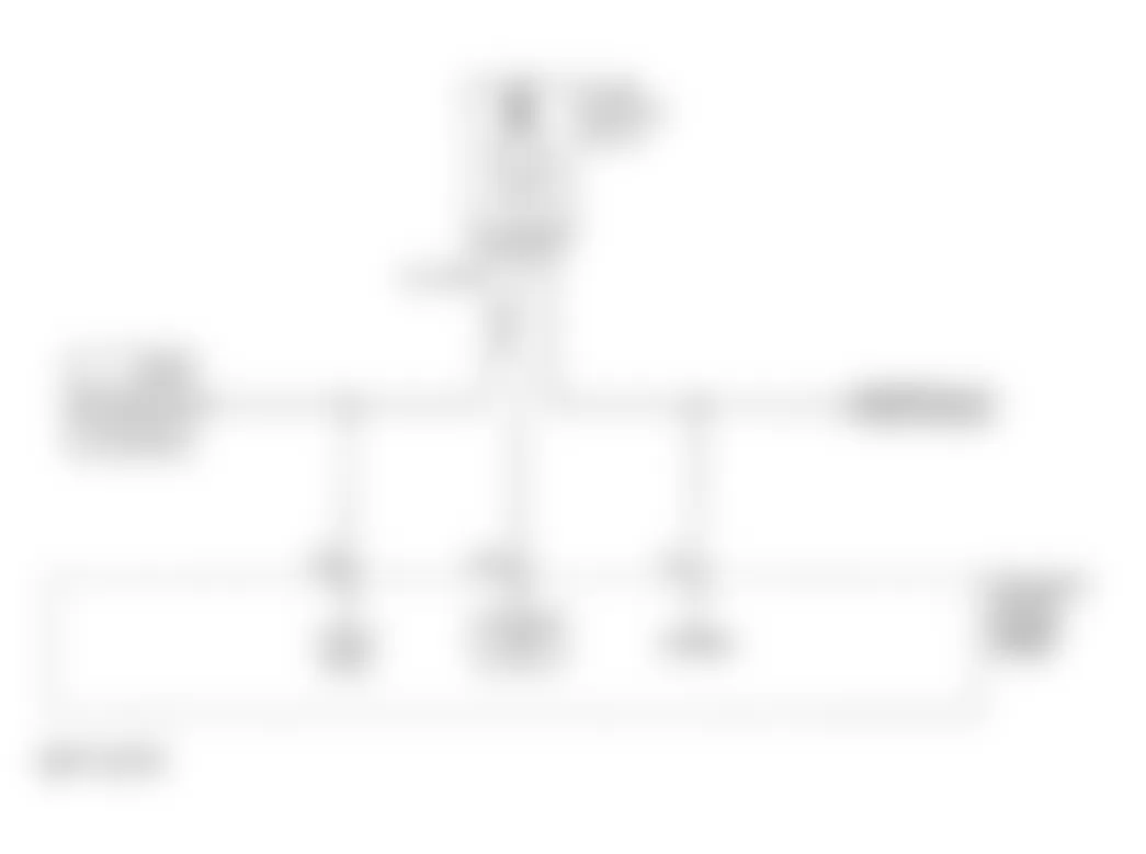
Isuzu Rodeo LS 1996 - Circuit Description
By using the G-sensor, the PCM can determine if changes in crankshaft speed are due to engine misfire or are educed by driveline condition. If the G-sensor detects a rough road condition, the PCM misfire detection diagnostic will be deactivated. At rest, G-sensor output is 2.5 volts. During operation, G-sensor output can vary between .5-4.5 volts.
Conditions required to set DTC are:
- G-sensor signal is less than .5 volts for 2 seconds over a 6.25-second period.
Isuzu Rodeo LS 1996 - Diagnostic Procedures
- Perform On-Board Diagnostic (OBD) System Check. Read and record FREEZE FRAME and/or FAIL RECORDS data for each DTC set. Go to next step.
- If DTC P1392 is set, repair that DTC first. If no other DTC is set, go to next step.
- Check for a poor connection at G-sensor harness connector. If a problem is found, go to step 8). If no problem is found, go to next step.
- Disconnect harness connectors from PCM and G-sensor. Using DVOM, check G-sensor signal circuit for intermittent open or short to ground. If a problem was found, go to step 9). If no problem is found, go to next step.
- Check reference circuit between PCM and MAP or G-sensor for an intermittent short to ground. If a problem is found, go to step 9). If no problem is found, go to next step.
- Check for poor reference terminal connection at PCM. If a problem is found, go to step 8). If no problem is found, go to next step.
- Check for an intermittent open or a faulty splice in reference circuit. If a problem is found, go to step 9). If no problem is found, go to DIAGNOSTIC AIDS.
- Repair poor reference circuit and G-sensor signal circuit harness connector terminals as necessary, and go to step 10).
- Repair intermittent open or short circuit in wiring harness as necessary and go to next step.
- Read and record FAIL RECORDS data for DTC P1390. Operate vehicle within conditions noted in FAIL RECORDS data. Using scan tool, read SPECIFIC DTC. If scan tool displays DTC P1390 FAILED THIS IGN, return to step 2). If scan tool does not display DTC P1390 FAILED THIS IGN, repair is complete.
Isuzu Rodeo LS 1996 - Diagnostic Aids
Check for poor connections at PCM. Inspect wiring harness for damage by, moving connectors and wiring harnesses while observing any change on scan tool G-sensor display. Since the G-sensor shares PCM reference and ground terminals with the MAP sensor, a damaged MAP harness or sensor could cause a g- sensor DTC to be set.
Isuzu Rodeo LS 1996 - DTC P1391 - G-SENSOR CIRCUIT PERFORMANCE
NOTE: For circuit reference, see Fig. 14 , Code P1390 schematic.
Isuzu Rodeo LS 1996 - Circuit Description
By using the G-sensor, the PCM can determine if changes in crankshaft speed are due to engine misfire or are educed by driveline condition. If the G-sensor detects a rough road condition, the PCM misfire detection diagnostic will be deactivated. At rest, G-sensor output is 2.5 volts. During operation, G-sensor output can vary between .5-4.5 volts.
Conditions required to set DTC are:
- Engine is running.
- Vehicle is not moving.
- G-sensor signal indicates greater than 2.5 volts or less than 1.5 volts for one minute.
Isuzu Rodeo LS 1996 - Diagnostic Procedures
- Perform On-Board Diagnostic (OBD) System Check. Read and record FREEZE FRAME and/or FAIL RECORDS data for each DTC set. Go to next step.
- Turn ignition on. Using scan tool, read and record FAIL RECORDS data for DTC P1391. Operate vehicle within conditions noted in FAIL RECORDS data. Using scan tool, read SPECIFIC DTC. If scan tool displays DTC P1391 FAILED THIS IGN, go to step 4). If scan tool does not display DTC P1391 FAILED THIS IGN, go to next step.
- Check for G-sensor seal missing or damaged, or mounting flanges cracked, missing or incorrectly installed. If problem is found, repair as necessary and go to step 14). If no problem is found, go to DIAGNOSTIC AIDS.
- Disconnect G-sensor electrical connector. Using scan tool, observe G-sensor value. If value is near zero volts, go to next step. If value is not as specified, go to step 12).
- Connect jumper wire between G-sensor reference and signal circuit at harness connector. Using scan tool, read G-sensor value. If G-sensor value is near 4.95 volts, go to next step. If value is not as specified, go to step 7).
- Turn ignition off. Disconnect PCM connector. Check sensor ground circuit for high resistless, poor connection at PCM, or an open between PCM and G-sensor. If a problem is found, repair as necessary and go to step 14). If no problem is found, go to step 10).
- Check reference circuit for high resistance, open between PCM and G-sensor or a poor connection at PCM. if a problem is found, repair as necessary and go to step 14). If no problem is found, go to next step.
- Check signal circuit for high resistance, open, short to ground or short to sensor ground. If a problem is found, repair as necessary and go to step 14). If no problem is found, go to next step.
- Check G-sensor circuit for poor connection at PCM. If a problem is found, repair as necessary and go to step 14). If no problem is found, go to step 13).
- Check for poor connection at G-sensor. If a problem is found, repair as necessary and go to step 14). If no problem is found, go to next step.
- Replace G-sensor and go to step 14).
- With ignition off, disconnect PCM. Turn ignition on, engine off. Check G-sensor signal circuit for a short to voltage or short to reference circuit. If a problem is found, repair as necessary and go to step 14). If no problem is found, go to next step.
- Replace PCM. Program replacement PCM using required equipment. After repair is completed, go to next step.
- Read and record FAIL RECORDS data for DTC P1391. Operate vehicle within conditions noted in FAIL RECORDS data. Using scan tool, read SPECIFIC DTC. If scan tool displays DTC P1391 FAILED THIS IGN, return to step 2). If scan tool does not display DTC P1391 FAILED THIS IGN, repair is complete.
Isuzu Rodeo LS 1996 - Diagnostic Aids
Check for poor connections at PCM. Inspect wiring harness for damage by, moving connectors and wiring harnesses while observing any change on scan tool G-sensor display. Since the G-sensor shares PCM reference and ground terminals with the MAP sensor, a damaged MAP harness or sensor could cause a g- sensor DTC to be set.
Isuzu Rodeo LS 1996 - DTC P1392 - G-SENSOR CIRCUIT - LOW VOLTAGE
NOTE: For circuit reference, see Fig. 14 , Code P1390 schematic.
Isuzu Rodeo LS 1996 - Circuit Description
By using the G-sensor, the PCM can determine if changes in crankshaft speed are due to engine misfire or are educed by driveline condition. If the G-sensor detects a rough road condition, the PCM misfire detection diagnostic will be deactivated. At rest, G-sensor output is 2.5 volts. During operation, G-sensor output can vary between .5-4.5 volts.
Isuzu Rodeo LS 1996 - Conditions required to set DTC are:
G-sensor signal is less than .5 volts for 12.5 seconds over a 25-second period.
Isuzu Rodeo LS 1996 - Diagnostic Procedures
- Perform On-Board Diagnostic (OBD) System Check. Read and record FREEZE FRAME and/or FAIL RECORDS data for each DTC set. Go to next step.
- Turn ignition on, engine off. Disconnect G-sensor electrical connector. Using scan tool, observe G-sensor value. If value is near zero volts, go to step 4). If value is not as specified, see ENGINE CRANKS BUT WILL NOT RUN in BASIC TESTING - 2.6L 4-CYL article.
- Turn ignition on. Using scan tool, read and record FAIL RECORDS data for DTC P1391. Operate vehicle within conditions noted in FAIL RECORDS data. Using scan tool, read SPECIFIC DTC. If scan tool displays DTC P1392 FAILED THIS IGN, go to next step. If scan tool does not display DTC P1392 FAILED THIS IGN, go to DIAGNOSTIC AIDS.
- Disconnect G-sensor electrical connector. Connect jumper wire between G-sensor reference and signal circuit at harness connector. Using scan tool, read G-sensor value. If G-sensor value is near 4.95 volts, go to step 9). If value is not as specified, go to next step.
- Turn ignition off. Disconnect PCM and check 5 volt reference circuit for an open or short to ground. If a problem is found, repair as necessary and go to step 10). If no problem is found, go to next step.
- Check 5 volt reference circuit for a poor connection at PCM. If a problem is found, repair as necessary and go to step 10). If no problem is found, go to next step.
- With ignition off, disconnect PCM. Check G-sensor signal circuit for open, short to ground or short to sensor ground. If a problem is found, repair as necessary and go to step 10). If no problem is found, go to next step.
- Check G-sensor signal circuit for a poor connection at PCM. Replace terminal if necessary and go to step 10). If no problem is found, go to next step.
- Replace PCM. Program replacement PCM using required equipment. After repair is completed, go to next step.
- Read and record FAIL RECORDS data for DTC P1391. Operate vehicle within conditions noted in FAIL RECORDS data. Using scan tool, read SPECIFIC DTC. If scan tool displays DTC P1391 FAILED THIS IGN, return to step 2). If scan tool does not display DTC P1391 FAILED THIS IGN, repair is complete.
Isuzu Rodeo LS 1996 - Diagnostic Aids
Check for poor connections at PCM. Inspect wiring harness for damage by, moving connectors and wiring harnesses while observing any change on scan tool G-sensor display. Since the G-sensor shares PCM reference and ground terminals with the MAP sensor, a damaged MAP harness or sensor could cause a G-sensor DTC to be set.
Isuzu Rodeo LS 1996 - DTC P1393 - G-SENSOR CIRCUIT - HIGH VOLTAGE
NOTE: For circuit reference, see Fig. 14 , Code P1390 schematic.
Isuzu Rodeo LS 1996 - Circuit Description
By using the G-sensor, the PCM can determine if changes in crankshaft speed are due to engine misfire or are educed by driveline condition. If the G-sensor detects a rough road condition, the PCM misfire detection diagnostic will be deactivated. At rest, G-sensor output is 2.5 volts. During operation, G-sensor output can vary between .5-4.5 volts.
Isuzu Rodeo LS 1996 - Conditions required to set DTC are:
G-sensor signal is greater than 4.5 volts for 12.5 seconds over a 25-second period.
Isuzu Rodeo LS 1996 - Diagnostic Procedures
- Perform On-Board Diagnostic (OBD) System Check. Read and record FREEZE FRAME and/or FAIL RECORDS data for each DTC set. Go to next step.
- Start engine and allow it to idle. Using scan tool read G-sensor value. If value is above 4.5 volts, go to step 4). If value is 4.5 volts or below, go to next step.
- Turn ignition on. Using scan tool, read and record FAIL RECORDS data for DTC P1391. Operate vehicle within conditions noted in FAIL RECORDS data. Using scan tool, read SPECIFIC DTC. If scan tool displays DTC P1392 FAILED THIS IGN, go to next step. If scan tool does not display DTC P1392 FAILED THIS IGN, go to DIAGNOSTIC AIDS.
- Turn ignition on, engine off. Disconnect G-sensor electrical connector. Using scan tool, observe G-sensor value. If value is near zero volts, go to next step. If value is not as specified, go to step 6).
- Connect a test light to battery positive and probe sensor ground. If test light illuminates, go to step 7). If test light does not illuminate, go to step 9).
- With ignition off, disconnect PCM. Turn ignition on, engine off. Check G-sensor signal circuit for a short to voltage or short to reference circuit. If a problem is found, repair as necessary and go to step 12). If no problem is found, go to step 11).
- Check for poor sensor ground terminal connection at G-sensor electrical connector. If a problem is found, replace faulty terminal and go to step 12). If no problem is found, go to next step.
- Check for a poor sensor ground terminal connection at PCM. If a problem is found, replace faulty terminal and go to step 12). If problem is not found, go to next step.
- Using DVOM, check continuity of G-sensor ground circuit. If reading is over 5 ohms of resistance, repair open or poor connection and go to step 12). If no problem is found, go to next step.
- Replace PCM. Program replacement PCM using required equipment. After repair is completed, go to step 12) .
- Replace G-sensor and go to next step.
- Read and record FAIL RECORDS data for DTC P1391. Operate vehicle within conditions noted in FAIL RECORDS data. Using scan tool, read SPECIFIC DTC. If scan tool displays DTC P1391 FAILED THIS IGN, return to step 2). If scan tool does not display DTC P1391 FAILED THIS IGN, repair is complete.
Isuzu Rodeo LS 1996 - Diagnostic Aids
Check for poor connections at PCM. Inspect wiring harness for damage by, moving connectors and wiring harnesses while observing any change on scan tool G-sensor display. Since the G-sensor shares PCM reference and ground terminals with the MAP sensor, a damaged MAP harness or sensor could cause a G-sensor DTC to be set.
Isuzu Rodeo LS 1996 - DTC P1394 - G-SENSOR CIRCUIT - INTERMITTENT HIGH VOLTAGE
NOTE: For circuit reference, see Fig. 14 , Code P1390 schematic.
Isuzu Rodeo LS 1996 - Circuit Description
By using the G-sensor, the PCM can determine if changes in crankshaft speed are due to engine misfire or are educed by driveline condition. If the G-sensor detects a rough road condition, the PCM misfire detection diagnostic will be deactivated. At rest, G-sensor output is 2.5 volts. During operation, G-sensor output can vary between .5-4.5 volts.
Isuzu Rodeo LS 1996 - Conditions required to set DTC are:
G-sensor signal is greater than 4.5 volts for 12.5 seconds over a 25-second period.
Isuzu Rodeo LS 1996 - Diagnostic Procedures
- Perform On-Board Diagnostic (OBD) System Check. Read and record FREEZE FRAME and/or FAIL RECORDS data for each DTC set. Go to next step.
- If DTC P1393 is also set, repair P1393 first. If DTC P1393 is not set, go to next step.
- If DTC P1106 and/or P1121 are also set, go to step 6). If DTC P1106 and/or P1121 are not set, go to next step.
- Check for poor sensor ground terminal connection at G-sensor electrical connector. If a problem is found, replace faulty terminal and go to step 9). If no problem is found, go to next step.
- Check for an intermittent short to voltage in G-sensor signal circuit between G-sensor connector and PCM connector. If a problem is found, go to step 10). If no problem is found, go to step 8).
- Check for an intermittent short to voltage in reference circuit between PCM and MAP sensor or G-sensor. If a problem is found, go to step 10). If no problem is found, go to next step.
- Check for a poor sensor ground circuit terminal connection at PCM. If a problem is found, go to step 9). If no problem is found, go to next step.
- Check for an intermittent open or a faulty splice in sensor ground circuit. If a problem is found, go to step 10). If no problem is found, go to DIAGNOSTIC AIDS.
- Replace faulty harness connector terminal for sensor ground circuit and go to step 11).
- Locate and repair intermittent open or short circuit in wiring harness as necessary and go to next step.
- Read and record FAIL RECORDS data for DTC P1391. Operate vehicle within conditions noted in FAIL RECORDS data. Using scan tool, read SPECIFIC DTC. If scan tool displays DTC P1391 FAILED THIS IGN, return to step 2). If scan tool does not display DTC P1391 FAILED THIS IGN, repair is complete.
Isuzu Rodeo LS 1996 - Diagnostic Aids
Check for poor connections at PCM. Inspect wiring harness for damage by, moving connectors and wiring harnesses while observing any change on scan tool G-sensor display. Since the G-sensor shares PCM reference and ground terminals with the MAP sensor, a damaged MAP harness or sensor could cause a G-sensor DTC to be set.
Isuzu Rodeo LS 1996 - DTC P1406 - EGR VALVE PINTLE POSITION CIRCUIT
Fig. 15: Isuzu Rodeo LS 1996 - Component Locations - EGR Valve Pintle Position Circuit (Rodeo 2.6L)
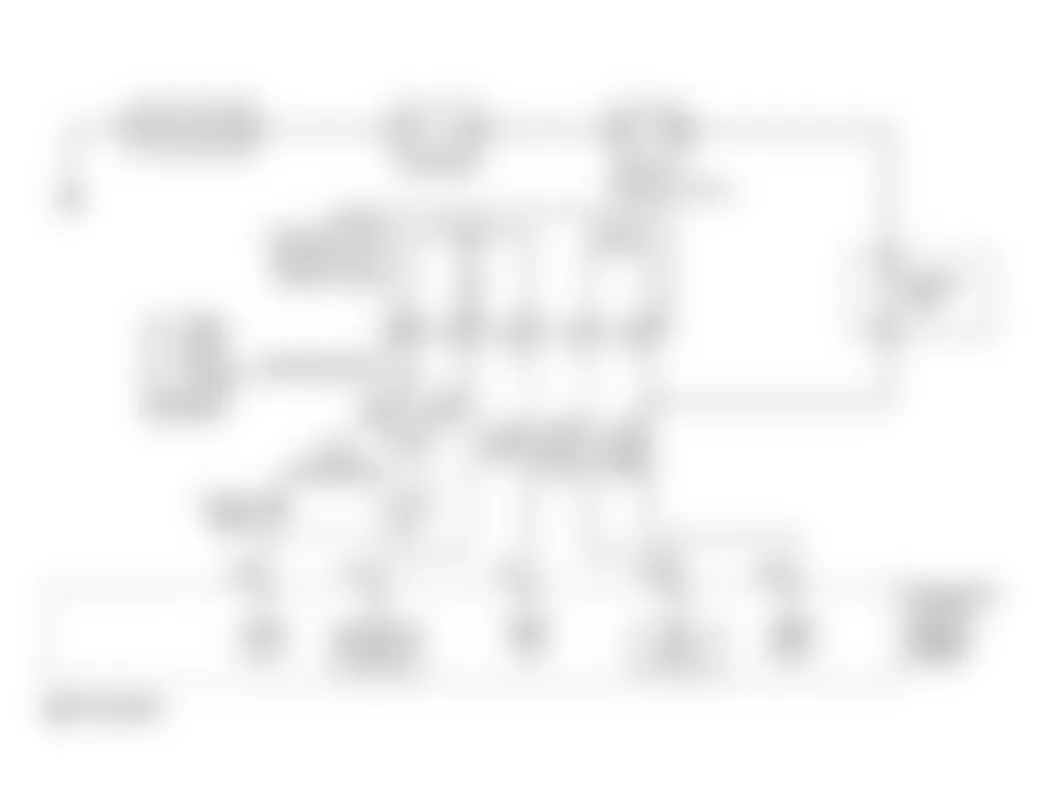
Isuzu Rodeo LS 1996 - Circuit Description
PCM monitors Exhaust Gas Recirculation (EGR) valve pintle position sensor to ensure valve is responding to commands from PCM.
Conditions required to set DTC are:
- Ignition voltage is between 11-16 volts.
- EGR feedback is less than 0.10 volt at any time for more than 5 seconds; or EGR feed back is .2 volts greater or less than EGR closed valve pintle position for more than five seconds, when desired EGR position is commanded to zero percent.
- Actual EGR position is three percent greater or less than desired EGR position for more than five seconds, when desired EGR position is commanded above zero percent.
Isuzu Rodeo LS 1996 - Diagnostic Procedures
- Perform On-Board Diagnostic (OBD) System Check. Read and record FREEZE FRAME and/or FAIL RECORDS data for each DTC set. Go to next step.
- Turn engine on and allow it to idle. Using scan tool, read EGR ACTUAL POS. If scan tool displays 0%, go to next step. If scan tool does not display 0%, go to step 10).
- Using scan tool, select MISC. TESTS and command EGR duty cycle through 25, 50, 75 and 100% positions. Compare scan tool display EGR DESIRED POSITION and EGR ACTUAL POS. If both readings are close, go to next. If readings are not close, go to step 5).
- Turn ignition on, engine off. Using scan tool, read and record FAILS RECORD DATA. Operate vehicle within conditions noted in FAILED RECORDS DATA. Read SPECIFIC DTC. If scan tool displays DTC P1406 FAILED THIS IGN, go to next step. If scan tool does not display DTC P1406 FAILED THIS IGN, see DIAGNOSTIC AIDS.
- Disconnect EGR valve harness connector. Connect a DVOM between EGR harness connector control and ignition feed circuits. Using scan tool, command EGR duty cycle to 25,50,75 and 100% position while observing voltage reading on DVOM. If readings are approximately 3 volts at 25 percent and go to battery voltage at 100 percent, go to step 16). if voltage does not increase as specified, go to next step.
- Turn ignition on. Connect a test light between engine ground and EGR valve harness connector ignition feed circuit. If test light illuminates, go to step 8). If test light does not illuminate, go to next step.
- Check EGR valve ignition feed circuit fuse. If fuse is blown, locate and repair short to ground in ignition feed circuit and go tostep 30). If fuse is okay, go to step 23).
- Turn ignition off. Disconnect PCM connectors. Check EGR control circuit for open. If open is found, repair as necessary and go tostep 30). If no open is found, go to next step.
- Check for faulty EGR control circuit connection at PCM. If faulty connection is found, repair as necessary and go to step 30). If connection is okay, go to step 29).
- Disconnect EGR valve harness connector. Using scan tool, read EGR ACTUAL POS. If scan tool displays 0%, go to step 12). If scan tool does not display 0%, go to next step.
- Turn ignition off. Disconnect PCM connectors. Turn ignition on. Check voltage between engine grounds and EGR pintle position circuit. If voltage is about zero volt, go to step 29). If voltage is not as specified, go to step 26).
- Connect a test light between battery voltage and EGR harness connector sensor ground circuit. If test light illuminates, go to step 14). If test light does not illuminate, go to next step.
- Check sensor ground circuit for faulty connection at PCM or open between PCM and EGR valve. If a problem is found, repair as necessary and go to step 30). If no problem is found, go to step 29).
- Connect a test light between battery voltage and EGR harness connector control circuit. If test light illuminates, go to next step. If test light does not illuminate, go to step 26).
- Turn ignition off. Disconnect PCM. Turn ignition on. Connect test light between battery voltage and EGR control circuit. If test light illuminates, go to step 27). If test light does not illuminate, go to step 29).
- Check voltage between EGR valve harness connector sensor ground and 5-volt reference circuits. If voltage is 5 volts, go to next step. If voltage is not as specified, go to step 22).
- Connect test light between battery voltage and EGR valve harness connector pintle position circuit. If test light illuminates,go to step 20). If test light does not illuminate, go to next step.
- Connect a jumper wire between EGR valve connector 5-volt reference and pintle position circuits. Using scan tool, read EGR DUTY CYCLE. If scan tool displays 100%, go to step 21). If scan tool does not display 100%, go to next step.
- Turn ignition off. Disconnect PCM connectors. Check pintle position circuit for open or faulty connection at PCM. If a problem is found, repair as necessary and go to step 30). If no problem is found, go to step 29).
- Turn ignition off. Disconnect PCM connectors. Connect test light between battery voltage and pintle position circuit. If test light does not illuminate, go to step 29). If test light illuminates, go to step 28).
- Check for faulty connection at EGR valve. If faulty connection is found, repair as necessary and go to step 30). If connection is okay, go to step 26).
- Check for open or short to ground in EGR 5-volt reference circuit. If no problem is found, go to step 24). If a problem is found, go tostep 30).
- Locate and repair open ignition feed circuit and go to step 30).
- Check EGR 5-volt reference circuit for faulty connection at PCM. If faulty connection is found, repair as necessary and go to step 30). If connection is okay, go to step 29).
- Locate and repair short to voltage in pintle position circuit and go to step 30).
- Replace EGR valve and go to step 30).
- Locate and repair short to ground in EGR control circuit and go to step 30).
- Locate and repair short to ground in pintle position circuit and go to step 30).
- Replace PCM. Program replacement PCM using required equipment. After repair is completed, go to next step.
- Read and record FAIL RECORDS data for DTC P1406. Operate vehicle within conditions noted in FAIL RECORDS data. Using scan tool, read SPECIFIC DTC. If scan tool displays DTC P1406 FAILED THIS IGN, return to step 3). If scan tool does not display DTC P1406 FAILED THIS IGN, repair is complete.
Isuzu Rodeo LS 1996 - Diagnostic Aids
Check for excessive deposits on EGR valve pintle or seat. Check for faulty EGR valve. Check for faulty connections or damaged harness. If connections and harness appear okay, observe EGR ACTUAL POS display on scan tool while moving all related harness and connectors. A change in scan tool display indicates fault location.
Isuzu Rodeo LS 1996 - DTC P1441 - EVAP SYSTEM FLOW DURING NON-PURGE
NOTE: For circuit reference, see Fig. 10 , Code P0441 schematic.
Isuzu Rodeo LS 1996 - Circuit Description
Evaporative (EVAP) emissions canister purge is controlled by a solenoid valve which allows ported vacuum to purge canister when energized (purge on) by PCM. A vacuum switch in purge line is used to detect when system is being purged. PCM supplies and reads EVAP purge vacuum switch signal. If switch is open (purge detected) when not commanded by PCM, DTC P1441 is set.
Conditions required to set DTC are:
- No ECT, IAT, MAF, MAP, or TP sensor DTCs set.
- BARO more than 10 psi (70 kPa).
- ECT less than 158?F (70?C).
- Start-up IAT and ECT above 41?F (5?C).
- Difference between ECT and IAT less than 45?F (25?C).
- TP indicating a throttle position above 13%.
- Battery voltage is between 11-16 volts.
- Engine speed above 800 RPM.
- EVAP canister purge duty cycle below 3%.
- EVAP canister purge vacuum switch open.
Isuzu Rodeo LS 1996 - Diagnostic Procedures
- Perform OBD-II System Check. Read and record FREEZE FRAME and/or FAIL RECORDS data for each DTC set. Go to next step.
- Turn ignition on, engine off. Using scan tool, read EVAP VACUUM SW. If scan tool displays NO PURGE, go to next step. If scan tool does not display NO PURGE, go to DTC P1442.
- Turn engine on and allow it to idle. Using scan tool, read EVAP VACUUM SW. while commanding EVAP purge solenoid off. If scan tool displays NO PURGE, go to next step. If scan tool does not display NO PURGE, go to step 5).
- Turn ignition on, engine off. Using scan tool, read and record FAILS RECORD DATA. Operate vehicle within conditions noted in FAILED RECORDS DATA. Read SPECIFIC DTC. If scan tool displays DTC P1441 FAILED THIS IGN, go to next step. If scan tool does not display DTC P1441 FAILED THIS IGN, go to DIAGNOSTIC AIDS.
- Disconnect EVAP purge solenoid harness connector. Allow engine to idle. Read EVAP VACUUM SW. If scan tool displays NO PURGE, go to next step. If scan tool does not display NO PURGE, go to step 7).
- Turn ignition off. Disconnect PCM connectors. Check EVAP purge solenoid driver circuit for short to ground. If short to ground is found, repair as necessary and go to step 11). If no short is found, go tostep 8).
- Leave EVAP purge solenoid harness connector disconnected. Disconnect vacuum signal hose from EVAP purge vacuum switch. Connect a vacuum gauge to signal hose. Allow engine to idle. If vacuum is more than 5 in H(2)O, go to step 9). If vacuum is 5 in H(2)O or less, go to step 10).
- Replace PCM. Replacement PCM requires special equipment for programming procedures. Go to next step.
- Replace EVAP purge solenoid and go to step 11).
- Replace EVAP vacuum switch and go to next step.
- Read and record FAIL RECORDS data for DTC P1441. Operate vehicle within conditions noted in FAIL RECORDS data. Using scan tool, read SPECIFIC DTC. If scan tool displays DTC P1441 FAILED THIS IGN, return to step 2). If scan tool does not display DTC P1441 FAILED THIS IGN, repair is complete.
Isuzu Rodeo LS 1996 - Diagnostic Aids
Check EVAP canister for damage or blockage. Check vacuum hoses for damage or incorrect routing. Check for restrictions in fuel vapor line, purge hose, or EVAP canister vent. Check for faulty connections or damaged harness. If connections and harness appear okay, observe EVAP VACUUM SW display on scan tool while moving all related harness and connectors. A change in scan tool display indicates fault location.
Isuzu Rodeo LS 1996 - DTC P1442 - EVAP SYS SWITCH - HI VOLTAGE DURING IGNITION ON
NOTE: For circuit reference, see Fig. 10 , Code P0441 schematic.
Isuzu Rodeo LS 1996 - Circuit Description
Evaporative (EVAP) emissions canister purge is controlled by a solenoid valve which allows ported vacuum to purge canister when energized (purge on) by PCM. A vacuum switch in purge line is used to detect when system is being purged. PCM supplies and reads EVAP purge vacuum switch signal. If switch is open (purge detected) when not commanded by PCM, DTC P1441 is set.
Conditions required to set DTC are:
- System output between 11-16 volts.
- No ECT, IAT, MAF, MAP, or TP sensor DTCs set.
- Start up IAT above 41?F (5?C).
- Start up ECT above 41?F (5?C) and below 122?F (50?C).
- EVAP purge vacuum switch is open during 4 out of 8 ignition on cycles.
Isuzu Rodeo LS 1996 - Diagnostic Procedures
- Perform OBD-II System Check. Read and record FREEZE FRAME and/or FAIL RECORDS data for each DTC set. Go to next step.
- Turn ignition on, engine off. Using scan tool, read EVAP VACUUM SW. If scan tool displays NO PURGE, go to next step. If scan tool does not display NO PURGE, go to step 4).
- Turn ignition on, engine off. Using scan tool, read and record FAILS RECORD DATA. Operate vehicle within conditions noted in FAILED RECORDS DATA. Read SPECIFIC DTC. If scan tool displays DTC P1441 FAILED THIS IGN, go to next step. If scan tool does not display DTC P1441 FAILED THIS IGN, go to DIAGNOSTIC AIDS.
- Turn ignition off, and disconnect EVAP purge vacuum switch harness connector. Connect a jumper wire between switch harness connector terminals. Using scan tool observe EVAP VACUUM SW. display. If EVAP VACUUM SW. displays NO PURGE, go to step 6). If EVAP VACUUM SW. does not displays NO PURGE, go to next step.
- Check for an open or short to ground in EVAP vacuum switch signal circuit between EVAP vacuum switch and PCM. Check for open EVAP vacuum switch ignition feed circuit. Check for poor EVAP vacuum switch signal circuit connection at PCM. If any problem is found, repair as necessary and go to step 9). If no problem is found, go to step 7).
- Check for poor connection at EVAP vacuum switch. If a problem is found, replace faulty terminals as necessary and go to step 9). If no problem is found, go to step 8).
- Replace PCM. Replacement PCM requires special equipment for programming procedures. Go to step 9).
- Replace EVAP vacuum switch and go to next step.
- Read and record FAIL RECORDS data for DTC P1442. Operate vehicle within conditions noted in FAIL RECORDS data. Using scan tool, read SPECIFIC DTC. If scan tool displays DTC P1442 FAILED THIS IGN, return to step 2). If scan tool does not display DTC P1442 FAILED THIS IGN, repair is complete.
Isuzu Rodeo LS 1996 - Diagnostic Aids
Check EVAP canister for damage or blockage. Check vacuum hoses for damage or incorrect routing. Check for restrictions in fuel vapor line, purge hose, or EVAP canister vent. Check for faulty connections or damaged harness. If connections and harness appear okay, observe EVAP VACUUM SW display on scan tool while moving all related harness and connectors. A change in scan tool display indicates fault location.
Isuzu Rodeo LS 1996 - DTC P1640 - DRIVER 1 - INPUT VOLTAGE HIGH Circuit Description
PCM contains Output Driver Modules (ODM) that provides 7 switchable ground outputs for operating solenoids, relays, indicator lights, and other devices. Each of these ground outputs has fault lines that feed back to the PCM's microprocessor. ODM No. 1 can also sense high voltage coming in which might damage microprocessor. DTC P1640 is used to monitor ODM No. 1 over voltage sense line.
Conditions required to set DTC are:
- Ignition is on.
- DTC P1618 is not set
- Ignition output is above 13.2 volts for 4 seconds.
Isuzu Rodeo LS 1996 - Diagnostic Procedures
- Perform On-Board Diagnostic (OBD) System Check. After performing OBD system check, go to next step.
- Turn ignition on, engine off. Using scan tools CAPTURE INFO feature, read and record FAILURE RECORDS DATA. Turn ignition off. Disconnect PCM and turn ignition on. Using DVOM, measure voltage between output driver circuit at PCM harness connector and ground. If reading is near battery voltage, go to next step. If voltage is not as specified, go to step 6).
- Set DVOM to 10 amp range and measure current between component output driver circuit and ground. Monitor current reading on DVOM for at least 2 minutes. If current reading remains between .05-1.5 amps, go to step 11). If reading is not as specified, go to next step.
- Turn ignition off and disconnect ignition feed circuit (leaving PCM disconnected). Turn ignition on. Using DVOM, measure voltage between output driver circuit and ground. If reading is at zero volts, go to step 10). If voltages not as specified, go to next step.
- Locate and repair short to voltage in component output driver circuit and go to step 15).
- Check components ignition feed fuse. If fuse is blown, go to next step. If fuse is not blown, go to step 8).
- Locate and repair short to ground in ignition feed circuit. Replace fuse and go to step 15).
- Disconnect ignition feed circuit. Turn ignition on and measure voltage between ignition feed circuit and ground. If DVOM reads battery voltage, go to next step. if voltage reading is not as specified, go to step 13).
- Check for an open or short to ground in output driver circuit. If a problem is found, repair as necessary and go to step 15). If no problem is found, go to next step.
- Check output driver circuit and ignition feed circuit at component and PCM for a poor connection. If a problem is found, repair as necessary and go to step 15). If no problem is found, see BASIC TESTING - 2.6L 4-CYL article for electrical diagnoses.
- Turn ignition off, reconnect PCM and disconnect instrument cluster. Turn ignition on, connect J34142-B test light or equivalent between the output driver circuit and ignition feed circuit at instrument panel harness connector. Using scan tool, select output test function and cycle component on and off. If test light flashes on and off, go to DIAGNOSTIC AIDS. If test light does not flash, go to next step.
- Check output driver circuit for a poor connection at PCM. If a problem is found, repair as necessary and go to step 15). If no problem is found, go to step 14).
- Repair open circuit in ignition feed circuit for component and go to step 15).
- Replace PCM. Program replacement PCM using required equipment and go to next step.
- Read and record FAIL RECORDS data for DTC P1640. Operate vehicle within conditions noted in FAIL RECORDS data. Using scan tool, read SPECIFIC DTC. If scan tool displays DTC P1640 FAILED THIS IGN, return to step 2). If scan tool does not display DTC P1640 FAILED THIS IGN, repair is complete.
Isuzu Rodeo LS 1996 - Diagnostic Aids
An overvoltage at ODM No. 1 will also trigger DTC P0563. Use DTC P0563 to diagnose if vehicle voltage is actually too high. A loose or faulty connection at generator terminal may cause DTC P1640 to set intermittently.
Isuzu Rodeo LS 1996 - SUMMARY
If no hard fault codes are present, driveability symptoms exist or intermittent codes exist, proceed to appropriate TESTS W/O CODES - 2.6L 4-CYL article for diagnosis by symptom (i.e., ROUGH IDLE, NO START, etc.) or intermittent diagnostic procedures.