
Isuzu Stylus XS 1991 - 1991 ENGINE PERFORMANCE Self-Diagnostics - Impulse & Stylus - Fuel Injection - 1.6L
Isuzu Stylus XS 1991 - INTRODUCTION
If no faults were found while performing BASIC TESTING , proceed with self-diagnostics. If no fault codes or only pass codes are present, proceed to H - EFI TESTS W/O CODES article in the ENGINE PERFORMANCE Section for diagnosis by symptom (i.e., ROUGH IDLE, NO START, etc.).
Isuzu Stylus XS 1991 - SELF-DIAGNOSTIC SYSTEM HARD FAILURES
Hard failures cause CHECK ENGINE light to illuminate and remain on until problem is repaired. If light comes on and remains on (light may flash) during vehicle operation, cause of malfunction must be determined using diagnostic (code) charts. If a sensor fails, Electronic Control Module (ECM) will use a substitute value in its calculations to continue engine operation. In this condition, commonly known as limp-in mode, the vehicle runs but driveability will not be optimum.
Isuzu Stylus XS 1991 - INTERMITTENT FAILURES
Intermittent failures may cause CHECK ENGINE light to flicker or illuminate and go out after intermittent fault goes away. However, the corresponding trouble code will be retained in Electronic Control Module (ECM) memory. If related fault does not reoccur within a certain time frame, related trouble code will be erased from ECM memory. Intermittent failures may be caused by a sensor, connector or wiring related problems. See INTERMITTENTS in H - EFI TESTS W/O CODES article in the ENGINE PERFORMANCE Section.
Isuzu Stylus XS 1991 - RETRIEVING CODES
NOTE: Codes can also be retrieved using a Scan tester.
- The CHECK ENGINE light will come on when ignition is on and engine is not running. When engine is started, CHECK ENGINE light should go off. If light remains on while engine is running, a trouble code is present.
- If light did not come on with key on and engine off, the CHECK ENGINE light circuit must be checked before continuing. See appropriate DIAGNOSTIC CIRCUIT CHECK in this article if CHECK ENGINE light failed to operate. Circuit checks are located with code charts.
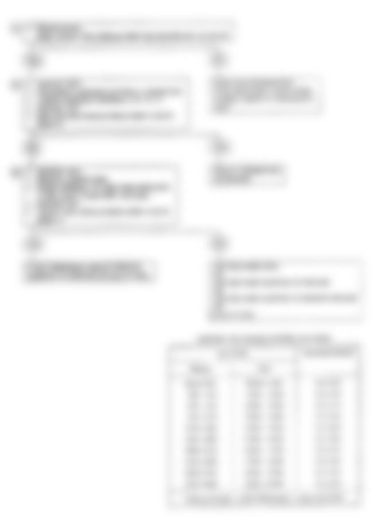
- To retrieve codes, install jumper wire between terminals No. 1 and No. 3 of ALDL connector located behind passenger's side kick panel. See Fig. 1

Fig. 1: Isuzu Stylus XS 1991 - Component Locations - Identifying ALDL Connector Terminals - Turn ignition on and count number of flashes from CHECK ENGINE light. All codes will be repeated 3 times. See Fig. 2 . Each additional code will flash 3 times starting with lowest code to the highest and repeat 3 times.
- If system is operating properly (with no trouble codes present), a Code 12 should be displayed with ignition on and engine off. This indicates the diagnostic system is capable of storing codes.
- Each individual code will be repeated 3 times and then display the next code. See Fig. 2 . Once all codes are displayed, codes will be repeated. Remove jumper wire from ALDL connector after codes have been retrieved.
Fig. 2: Isuzu Stylus XS 1991 - Component Locations - Code Display (Typical)

Isuzu Stylus XS 1991 - CLEARING TROUBLE CODES
CAUTION: Ensure ignition is off when disconnecting or reconnecting power supply to ECM.
- After repairs are performed, clear ECM memory of all stored trouble codes. To clear memory, turn ignition off and remove ECM fuse (30A) from engine compartment fuse block for at least 30 seconds. Replace fuse.
- After clearing trouble codes, confirm that system will operate in closed loop mode and ensure that CHECK ENGINE light functions properly.
NOTE: Trouble codes can also be cleared by disconnecting vehicle battery. However, other memory functions (clock, radio, etc.), will require resetting.
Isuzu Stylus XS 1991 ECM LOCATIONS
Model Location Impulse DOHC (Non-Turbo) (1) Below Instrument Panel, Left Of Steering Column DOHC (Turbo) (1) Behind Driver's Side Kick Panel Stylus DOHC (1) Below Instrument Panel, Left Of Steering Column SOHC (1) Behind Driver's Side Kick Panel
(1) DO NOT confuse transaxle Electronic Control Unit (ECU), located on left side of instrument panel, with ECM located behind air duct. The ECM has a 24-pin and 32-pin connector. Transaxle ECU has a 16-pin and 20-pin connector.
Isuzu Stylus XS 1991 - TROUBLE CODE CHARTS
Isuzu Stylus XS 1991 TROUBLE CODE IDENTIFICATION
Code System Affected Probable Cause 12 System Normal System Normal 13 O2 Sensor (Open) (DOHC Non-Turbo) Sensor or Circuit, ECM 13 O2 Sensor (Open) (Turbo) Sensor or Circuit, ECM 13 O2 Sensor (Open) (SOHC) Sensor or Circuit, ECM 14 (1) (2) Coolant Temp. Sensor Sensor or Circuit, ECM 14A Coolant Temp. Sensor Sensor or Circuit, ECM 14B Coolant Temp. Sensor Sensor or Circuit, ECM 15 (2) (3) Coolant Temp. Sensor Sensor or Circuit, ECM 21 (2) TPS Signal (High) Sensor or Circuit, ECM 21A TPS Signal (High) Sensor or Circuit, ECM 21B TPS Signal (Low) Sensor or Circuit, ECM 22 (2) TPS Signal (Low) Sensor or Circuit, ECM 23 (2) (3) MAT Sensor Sensor or Circuit, ECM 23A MAT Sensor Sensor or Circuit, ECM 23B MAT Sensor Sensor or Circuit, ECM 24 Vehicle Speed Sensor Sensor or Circuit, ECM 25 (1) (2) MAT Sensor Sensor or Circuit, ECM 31 (2) Turbo Overboost Wastegate Actuator, Control Valve, Vacuum Hose, Air Filter, ECM 32 EGR Temp. Sensor EGR Valve, Sensor or Circuit, ECM 33 (2) MAP Sensor (High) Sensor or Circuit, ECM 33A MAP Sensor (High) Sensor or Circuit, ECM 33B MAP Sensor (Low) Sensor or Circuit, ECM 34 (2) MAP Sensor (Low) Sensor or Circuit, ECM 41 (2) Cam Signal Sensor or Circuit, ECM 42 Elec. Spark Timing Circuit, Ign. Module, ECM 43 (2) Elec. Spark Control Knock Sensor or Circuit, MEM-CAL, ECM 44 O2 Sensor (Lean) (DOHC Non-Turbo) Injectors, Fuel Pressure, EGR, Exhaust Leaks, O2 Sensor or Circuit, MAP Sensor, ECM 44 O2 Sensor (Lean) (Turbo) Injectors, Fuel Pressure, EGR, Exhaust Leaks, O2 Sensor or Circuit, MAP Sensor, ECM 44 O2 Sensor (Lean) (SOHC) Injectors, Fuel Pressure, EGR, Exhaust Leaks, O2 Sensor or Circuit, MAP Sensor, ECM 45 O2 Sensor (Rich) (DOHC Non-Turbo) Injectors, Fuel Pressure, EGR, O2 Sensor or Circuit, MAP Sensor, TPS, Canister Purge, Ignition Shielding, ECM 45 O2 Sensor (Rich) (Turbo) Injectors, Fuel Pressure, EGR, O2 Sensor or Circuit, MAP Sensor, TPS, Canister Purge, Ignition Shielding, ECM 45 O2 Sensor (Rich) (SOHC) Injectors, Fuel Pressure, EGR, O2 Sensor or Circuit, MAP Sensor, TPS, Canister Purge, Ignition Shielding, ECM 51 ECM/MEM-CAL Failure ECM, EEPROM or MEM-CA Failure
(1) High temperature indicated by temperature sensor.
(2) Impulse turbocharged 1.6L only.
(3) Low temperature indicated by temperature sensor.
Isuzu Stylus XS 1991 - DIAGNOSTIC CIRCUIT CHECK
The diagnostic circuit check will identify a problem created by an Electronic Engine Control System (EECS) malfunction. It is the starting point for diagnosis. This directs you to the next logical step in diagnosing a complaint.
After completing diagnostic circuit check and finding on-board diagnostics functioning properly with no trouble codes displayed, use appropriate SCAN DATA table for comparison. The typical values are an average of display values recorded from a properly operating vehicle and are intended to represent a normal system display.
NOTE: Only parameters supplied by manufacturer are used in this article. If a Scan tester reads other parameters, values are not recommended by manufacturer for diagnostic use. A Scan tester displaying faulty data should not be used or a misdiagnosis will occur. Report problem to Scan tester manufacturer.
Fig. 3: Isuzu Stylus XS 1991 - Component Locations - Diagnostic Circuit Check Flow Chart
Isuzu Stylus XS 1991 SCAN DATA
Scan Position (1) Data Value A/C Clutch Off A/C Request No Base Pulse Width (BPW) .8-3.0 Milliseconds Battery 13.5-14.5 Volts Block Learn Cell 0 Block Learn Enable No Block Learn Memory (BLM) 118-138 Counts Coolant Temperature 185-221?F (85-105?C) Desired RPM ECM Idle Command EGR Solenoid Off EGR Temp. Signal 0-5 Volts Engine RPM DOHC (Non-Turbo) 800-900 RPM DOHC (Turbo) 800-1000 RPM SOHC A/T 890-990 RPM M/T 800-900 RPM IAC 1-50 Counts Idle Throttle No Integrator (INT) 110-145 Counts MAP (2) .5-2.0 Volts MAT Temperature (3) 50-194?F (10-90?C) Open/Closed Loop Closed Loop (Open w/Extended Idle) Oxygen Sensor (4) 0.1-1.0 Millivolts Park/Neutral Switch Park/Neutral Power Steering Switch Normal Shift Light (M/T) Off Spark Advance Varies Throttle Angle 0-1% TPS 0.4-1.25 Volts Vehicle Speed 0
(1) With engine at idle, normal operating temp., Park or Neutral, system in closed loop and all accessories off.
(2) Depending on vacuum and barometric pressure.
(3) Depending on underhood temperature.
(4) Voltage will continuously vary.
Isuzu Stylus XS 1991 - ECM TERMINAL IDENTIFICATION-DOHC (NON-TURBO)

Isuzu Stylus XS 1991 ECM CONNECTOR C-47 TERMINAL PIN ID (DOHC NON-TURBO) (1) (2)
PIN & (WIRE COLOR) CIRCUIT NAME C47-1 (Pnk/Wht) Fuel Pump Relay C47-2 (Gry/Red) A/C Cut-Out Relay C47-4 (Wht/Blu) Intake Air Solenoid C47-5 (Vlt) Check Engine Light C47-6 (Red/Grn) Ign. Feed Main Relay C47-8 (Orn/Blk) Serial Data Output C47-9 (Orn/Yel) Diagnostic Request C47-10 (White) VSS Signal Output C47-11 (Gray) Coolant/MAP Sensor Grnd C47-12 (Blk/Blu) Engine Ground C47-13 (Red/Wht) SBF Box 30A C47-15 (Yel/Blk) Distributor Ref. Ground C47-17 (Yel/Red) Dist. Ref Signal Input C47-20 (Grn/Orn) A/C Request Input C47-22 (Pnk/Blu) P/N Switch
(1) Terminal C47-1 through C47-12 correspond to A-1 through A-12 and C47-13 through C47-24 correspond to B-1 through B-12.
(2) Terminals not listed are not used.
Isuzu Stylus XS 1991 ECM CONNECTOR C-46 TERMINAL PIN ID (DOHC NON-TURBO) (1) (2)
PIN & (WIRE COLOR) CIRCUIT NAME C46-1 (Orn/Blu) PWM TPS C46-3 (Brn/Yel) IAC (Coil B Low) C46-4 (Brn/Red) IAC (Coil B High) C46-5 (Brn/Blk) IAC (Coil A High) C46-6 (Brn/Wht) IAC (Coil A Low) C46-7 (Grn/Yel) P/S Switch Input C46-10 (Gry/Blk) Coolant Temp Sensor Input C46-11 (Gry/Red) MAP Sensor Signal Input C46-12 (Blu/Blk) MAT Sensor Signal Input C46-13 (Blu/Red) TPS Signal Input C46-14 (Blu/Orn) 5V Reference Output C46-15 (Blu/Yel) Injector 1 & 3 Driver C46-16 (Red/Wht) SBF Box (30A) C46-17 (Blk/Blu) Engine Ground C46-18 (Blk/Wht) TPS, MAT Sensor Ground C46-19 (Pnk/Grn) Peak & Hold Jumper D9 C46-20 (Yellow) EST Output C46-21 (Yel/Grn) Ignition Module Bypass C46-22 (Blk/Blu) O2 Sensor Engine Ground C46-23 (Lt Blu) O2 Sensor Input Signal C46-24 (Pnk/Blk) Peak & Hold Jumper D13 C46-25 (Pnk/Grn) Peak & Hold Jumper D3 C46-28 (Wht/Grn) EGR Control C46-29 (Pnk/Blk) Peak & Hold Jumper D8 C46-30 (Blu/Wht) Injector 1 & 3 Driver
(1) Terminal C46-1 through C46-16 correspond to C-1 through C-16 and C46-17 through C46-32 correspond to D-1 through D-16.
(2) Terminals not listed are not used.
Isuzu Stylus XS 1991 - ECM TERMINAL IDENTIFICATION-DOHC (TURBO)
Fig. 5: Isuzu Stylus XS 1991 - Component Locations - ECM Connector & Terminal Pin ID (DOHC Turbo)
Isuzu Stylus XS 1991 ECM CONNECTOR A-B TERMINAL PIN ID (DOHC TURBO) (Terminals not listed are not used)
PIN & (WIRE COLOR) CIRCUIT NAME A1 (Grn/Wht) Fuel Pump Relay Control A2 (Gry/Red) A/C Clutch Relay Control A3 (Wht/Red) Canister Purge VSV Cntrl A4 (Wht/Blu) Secondary Intake Control A5 (Purple) Check Engine Light A6 (Red/Grn) Ignition Voltage Signal A8 (Orn/Blk) Serial Data Input/Output A9 (Orn/Yel) Diagnostic/ALDL Input A10 (White) VSS Input A11 (Gray) CTS & MAP Sensor Ground A12 (Blk/Blu) System Ground B1 (Red/Wht) Battery Feed B2 (Blk/Red) Fuel Pump Voltage Monitor B3 (Yel/Ppl) Reference Low B4 (Black) Cam Angle Sensor Low B5 (Yel/Red) Reference High B8 (Grn/Orn) A/C Request Signal B9 (Yel/Blu) Cam Angle Sensor High B11 (Blu/Pnk) Knock Signal Input B12 (Gry/Blu) EGR Temp Sensor Input
Isuzu Stylus XS 1991 ECM CONNECTOR C-D TERMINAL PIN ID (DOHC TURBO) (Terminals not listed are not used)
PIN & (WIRE COLOR) CIRCUIT NAME C2 (Wht/Ppl) Waste Gate VSV C3 (Brn/Yel) IAC Low C4 (Brn/Red) IAC High C5 (Brn/Blk) IAC High C6 (Brn/Wht) IAC Low C7 (Grn/Yel) PSPS Signal C10 (Gry/Blk) CTS Signal Input C11 (Gry/Red) MAP Signal Input C12 (Blu/Blk) MAT Signal Input C13 (Yel/Blu) TPS Signal Input C14 (Blu/Orn) 5V Reference, MAP & TPS C15 (Blu/Yel) Injector Driver 1 & 3 C16 (Red/Wht) Battery Feed D1 (Blk/Blu) System Ground D2 (Blk/Wht) TPS & MAP Sensor Ground D3 (Pnk/Grn) Peak & Hold Jumper 2 & 4 D4 (Yellow) EST Output D5 (Yel/Grn) Bypass Control D6 (Blk/Blu) O2 Circuit Ground D7 (Lt Blu) O2 Signal D8 (Pnk/Blk) Peak & Hold Jumper 1 & 3 D9 (Pnk/Grn) Peak & Hold Jumper 2 & 4 D12 (Wht/Grn) EGR VSV Control D13 (Pnk/Blk) Peak & Hold Jumper 1 & 3 D15 (Blu/Wht) Injector Driver 2 & 4
Isuzu Stylus XS 1991 - ECM TERMINAL IDENTIFICATION-SOHC
Fig. 6: Isuzu Stylus XS 1991 - Component Locations - ECM Connector & Terminal Pin ID (SOHC)
Isuzu Stylus XS 1991 ECM CONNECTOR C47 (24 PIN) TERMINAL PIN ID (1) (2)
PIN & (WIRE COLOR) CIRCUIT NAME C47-1 (Pnk/Wht) Fuel Pump Relay C47-2 (Gry/Red) A/C Cut-Out Relay C47-5 (Vlt) Check Engine Light C47-6 (Red/Grn) Ignition Feed Main Relay C47-8 (Orn/Blk) Serial Data Output C47-9 (Orn/Yel) Diagnostic Request C47-10 (White) VSS Signal Output C47-11 (Gray) Coolant, MAP Sensor Ground C47-12 (Blk/Blu) ECM Ground C47-13 (Red/Wht) SBF Box 30A C47-15 (Yel/Blk) Distributor Reference Ground C47-17 (Yel/Red) Distributor Reference Signal Input C47-20 (Grn/Orn) A/C Request Input C47-22 (Pnk/Blu) P/N Switch (A/T) C47-24 (Gry/Blu) EGR GAS Temp Sensor Input
(1) Terminal C47-1 through C47-12 correspond to A-1 through A-12 and C47-13 through C47-24 correspond to B-1 through B-12.
(2) Terminals not listed are not used.
Isuzu Stylus XS 1991 ECM CONNECTOR C46 (32 PIN) TERMINAL PIN ID (1) (2)
PIN & (WIRE COLOR) CIRCUIT NAME C46-1 (Orn/Blu) Shift Indicator Relay C46-3 (Brn/Yel) IAC (Coil B Low) C46-4 (Brn/Red) IAC (Coil B High) C46-5 (Brn/Blk) IAC (Coil A High) C46-6 (Brn/Wht) IAC (Coil A Low) C46-7 (Grn/Yel) P/S Switch Input C46-10 (Gry/Blk) Coolant Temp Sensor Input C46-11 (Gry/Red) MAP Sensor Signal Input C46-12 (Blu/Blk) MAT Sensor Signal Input C46-13 (Blu/Red) TPS Signal Input C46-14 (Blu/Orn) 5V Reference Output C46-15 (Blu/Yel) Injector 3 & 4 Driver C46-16 (Red/Wht) SBF Box (30A) C46-17 (Blk/Blu) ECM Ground C46-18 (Black) TPS, MAT Sensor Ground C46-19 (Blk/Blu) Engine Ground C46-20 (Yellow) EST Output C46-21 (Yel/Grn) Ignition Module Bypass C46-22 (Blk/Blu) O2 Sensor Engine Ground C46-23 (Lt Blu) O2 Sensor Input Signal C46-24 (Blk/Blu) Engine Ground C46-28 (Wht/Grn) EGR Control C46-31 (Blu/Wht) Injector 1 & 2 Driver
(1) Terminal C46-1 through C46-16 correspond to C-1 through C-16 and C46-17 through C46-32 correspond to D-1 through D-16.
(2) Terminals not listed are not used.
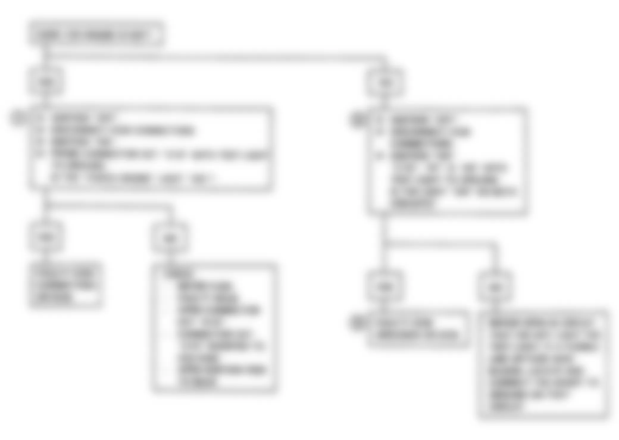
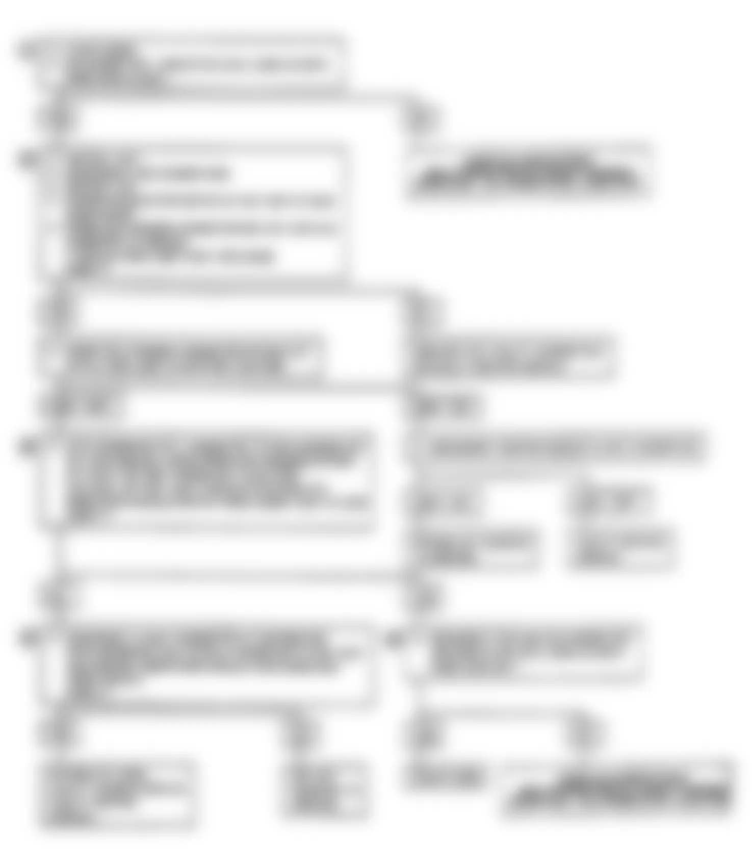
Isuzu Stylus XS 1991 - CHART A-1, NO CHECK ENGINE LIGHT (NON-TURBO)
There should always be a steady CHECK ENGINE light when ignition is on and engine stopped. Battery voltage is supplied to bulb through C7 fuse. The Electronic Control Module (ECM) turns the light on by providing a ground path through Violet wire.
NOTE: Test numbers refer to test numbers on diagnostic chart.
- Battery voltage at circuit No. 240 is protected by a fusible link, located in relay/fuse box under the hood, near the battery.
- If voltage is present on circuit No. 240, check for faulty ECM ground or ECM.
- Using a test light connected to 12 volts, probe each system ground circuits to ensure a good ground is present.
Isuzu Stylus XS 1991 - Diagnostic Aids
Engine Runs Okay - Check for a faulty light bulb, open in circuit No. 419 or defective C7 (10-amp) fuse. This will result in no oil or alternator lights, seat belt reminder, etc.
Engine Cranks, But Will Not Run - Check for open in battery fuse or fusible link, ECM ignition fuse, battery circuit No. 240 to ECM, ignition circuit No. 439 to ECM, or poor connection at ECM.
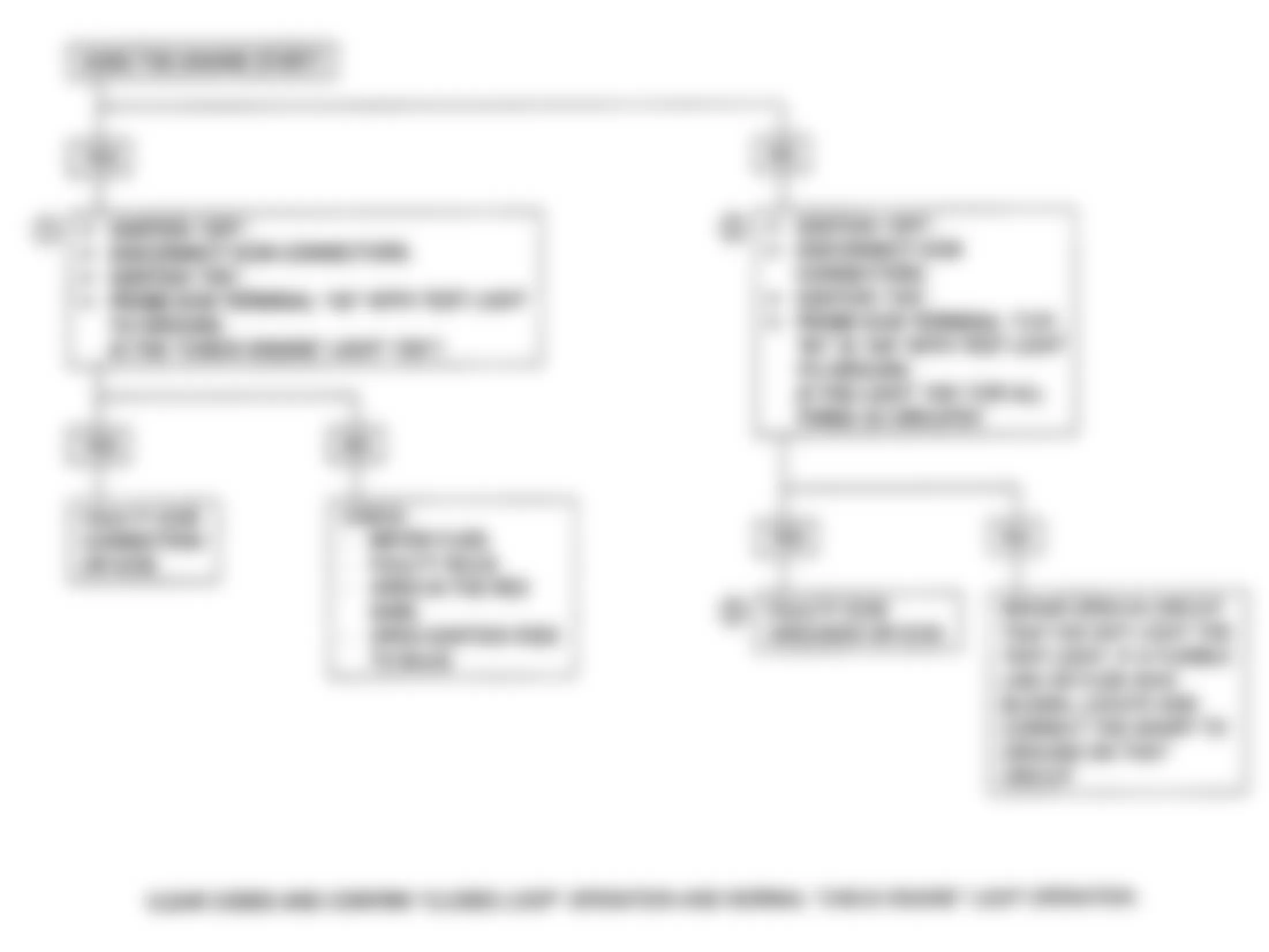
Isuzu Stylus XS 1991 - CHART A-1, NO CHECK ENGINE LIGHT (TURBO)
There should always be a steady CHECK ENGINE light when ignition is on and engine stopped. Battery voltage is supplied to bulb through C7 (10-amp) fuse. The Electronic Control Module (ECM) turns the light on by providing a ground path through Purple wire.
NOTE: Test numbers refer to test numbers on diagnostic chart.
- Battery voltage terminals B1 and C16 are protected by a fusible link, located in relay/fuse box under the hood, near the battery.
- If voltage is present at terminals B1 and C16, check for faulty ECM grounds or faulty ECM.
- Using a test light connected to 12 volts, probe each system ground circuits to ensure a good ground is present.
Isuzu Stylus XS 1991 - Diagnostic Aids
Engine Runs Okay - Check for a faulty light bulb, open in Purple wire, or defective C7 (10-amp) fuse. A blown fuse will result in no oil or alternator lights, seat belt reminder, etc.
Engine Cranks, But Will Not Run - Check for open in battery fuse or fusible link, ECM ignition fuse, battery Red/White wire to ECM, ignition Red/Green wire to ECM, or poor connection at ECM.

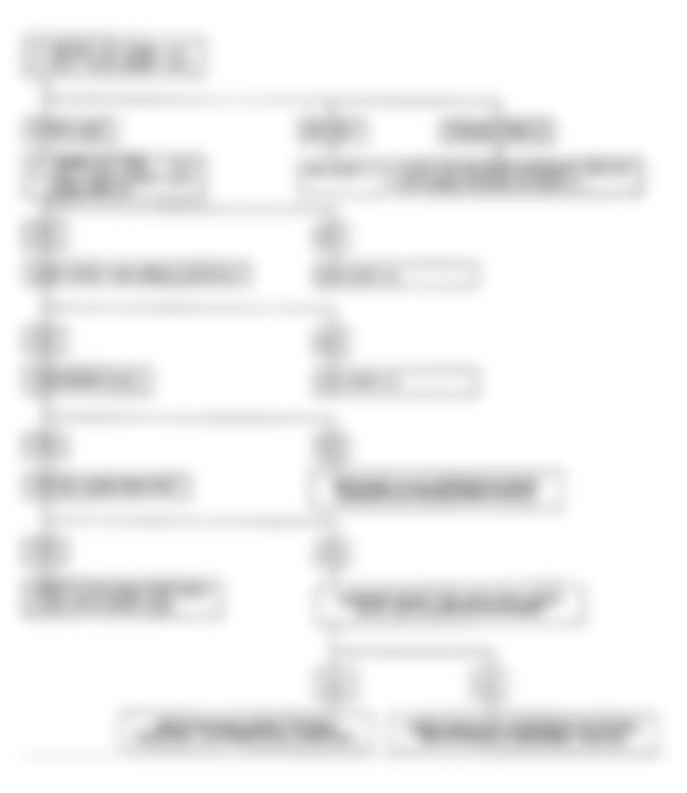
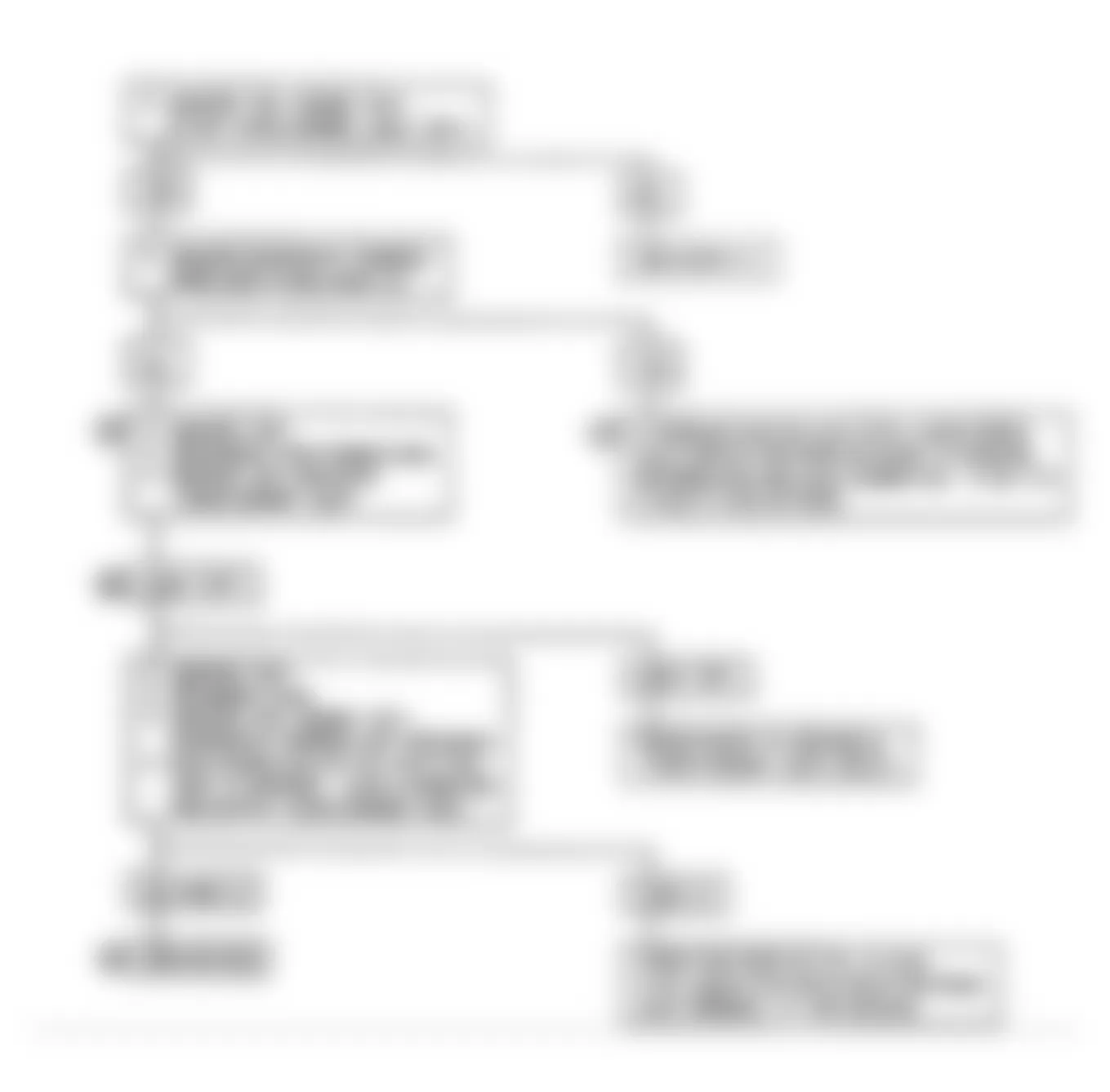
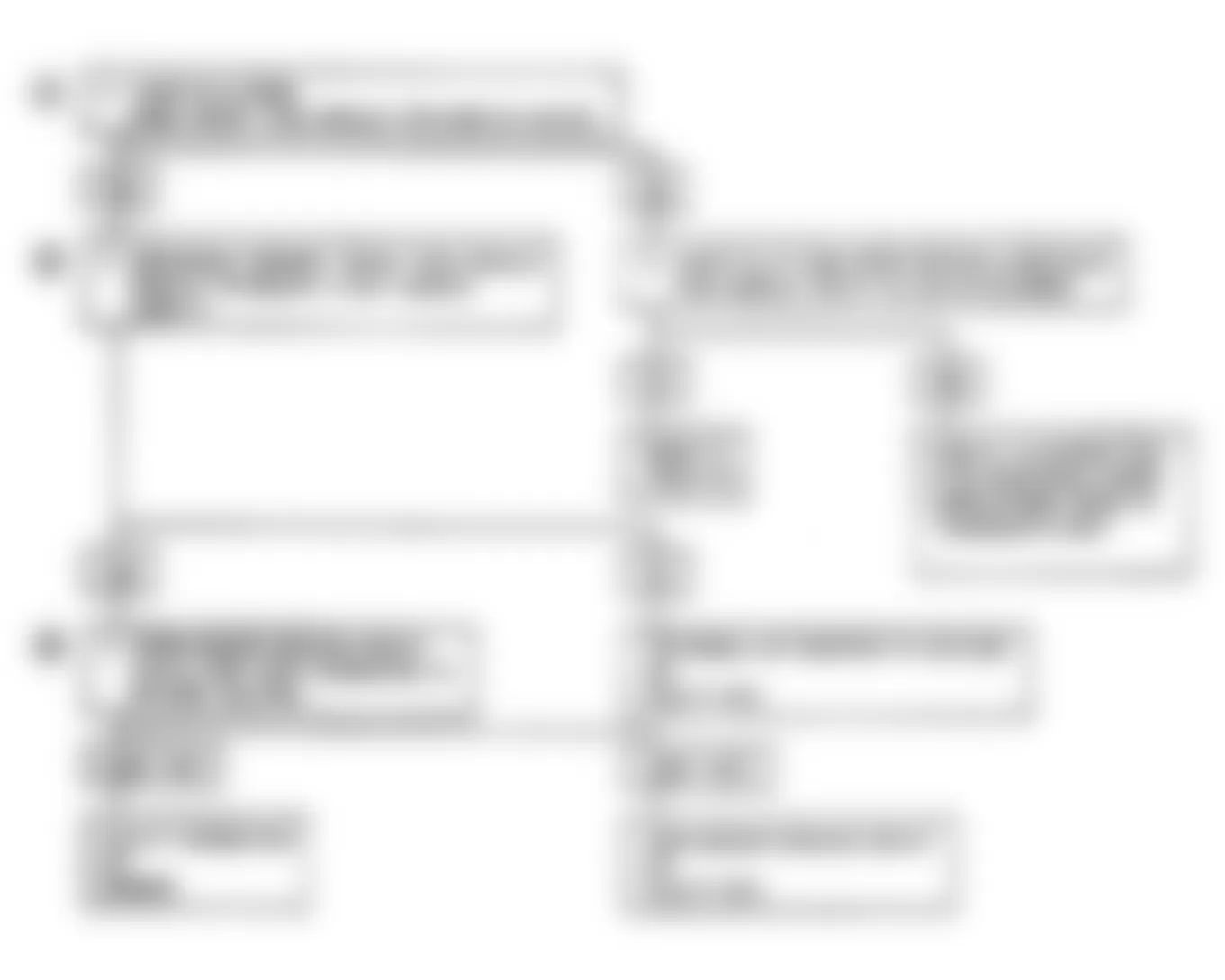
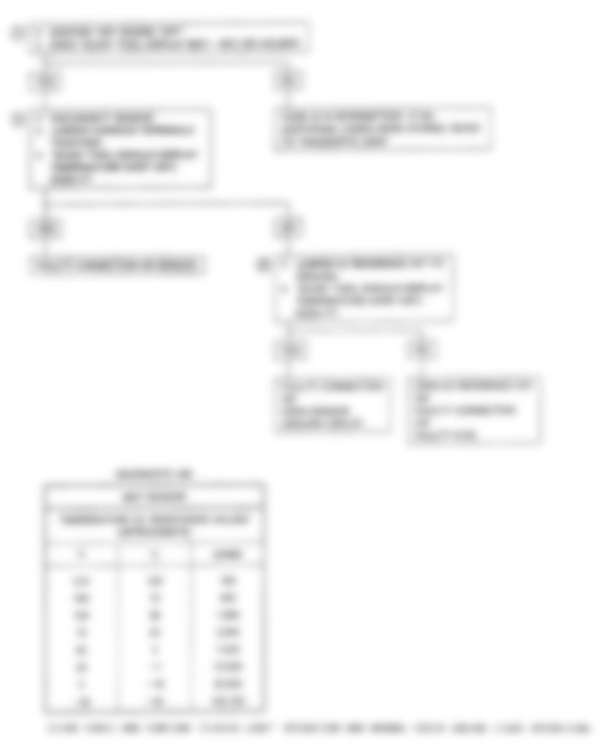
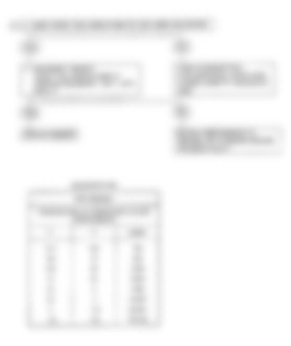
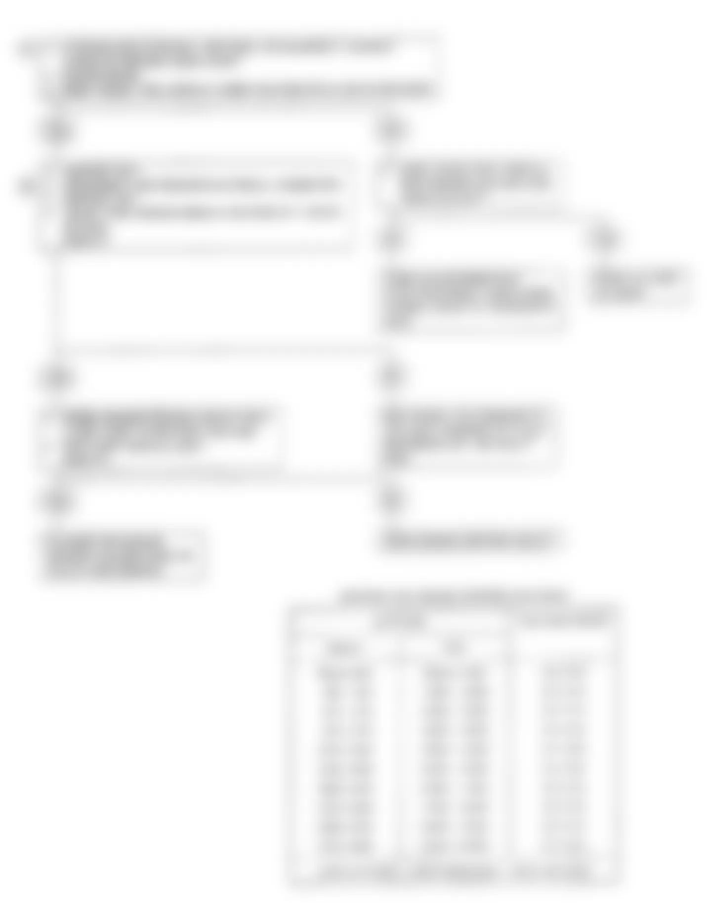
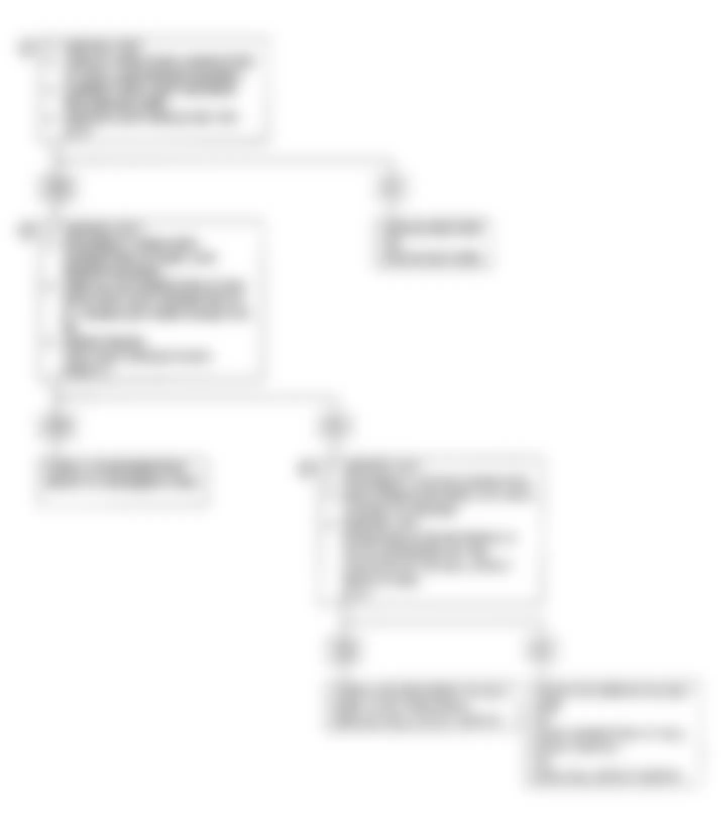
Isuzu Stylus XS 1991 - CHART A-2, NO ALDL DATA OR WON'T FLASH CODE 12 (NON-TURBO)
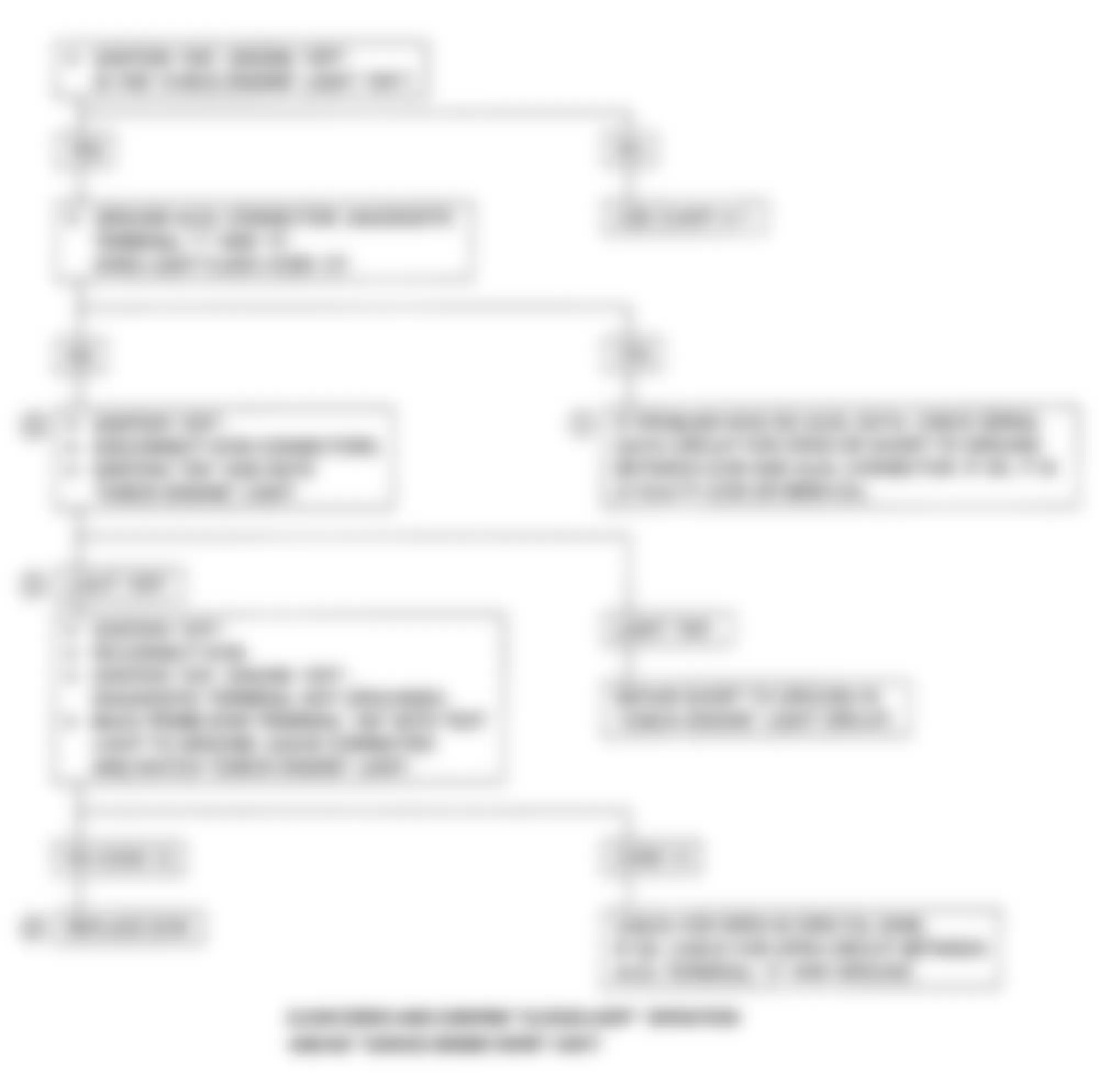
There should always be a steady CHECK ENGINE light when ignition is on and engine off. Battery voltage is supplied to the bulb by the ECM, which activates the light by grounding Violet wire. With diagnostic terminal grounded, light should flash a Code 12, followed by any trouble codes stored in memory. A steady light could be a short to ground in the light control circuit No. 419 (Violet wire), or an open in diagnostic circuit No. 451 (Orange/Yellow wire).
NOTE: Test numbers refer to test numbers on diagnostic chart.
- If a problem exists with the ECM that causes a Scan tester not to read serial data, ECM should NOT flash a Code 12. If Code 12 does flash, ensure Scan tester is working properly on another vehicle. If Scan tester is functioning properly and circuit No. 461 (serial data) is okay, the ECM may be at fault.
- If light goes off when ECM connector is disconnected, circuit No. 419 is NOT shorted to ground.
- This tests for an open in circuit No. 451 (diagnostic enable).
- At this point, CHECK ENGINE light wiring is okay. The problem is a faulty ECM. If Code 12 does not flash, replace ECM.

Fig. 12: Isuzu Stylus XS 1991 - Component Locations - Chart A-2 Flow Chart-No ALDL Data (Non-Turbo)
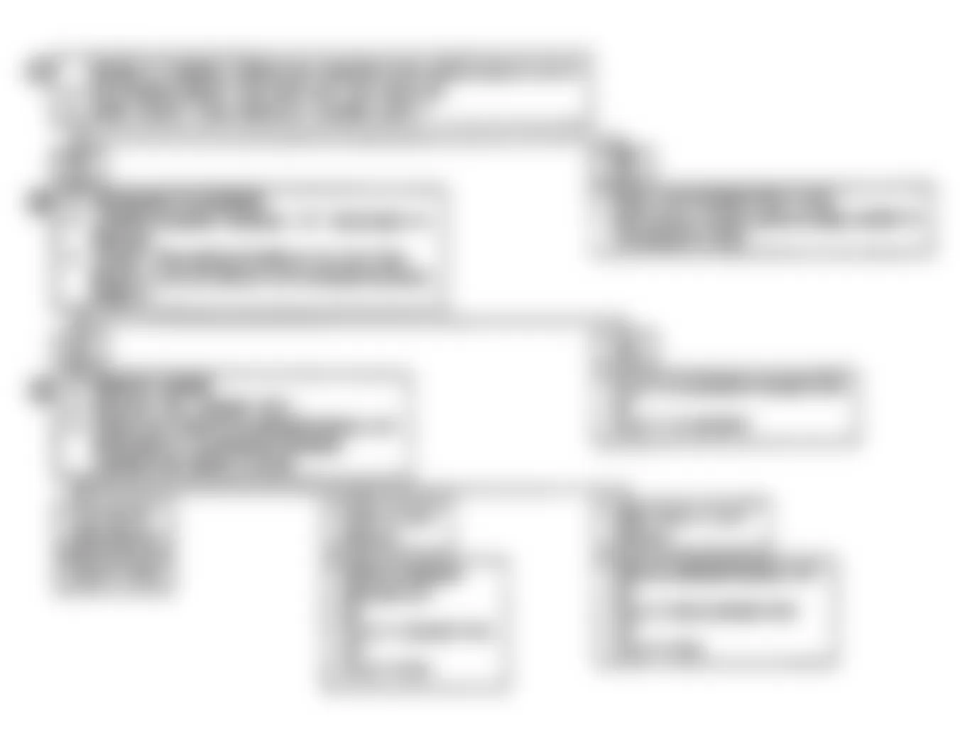
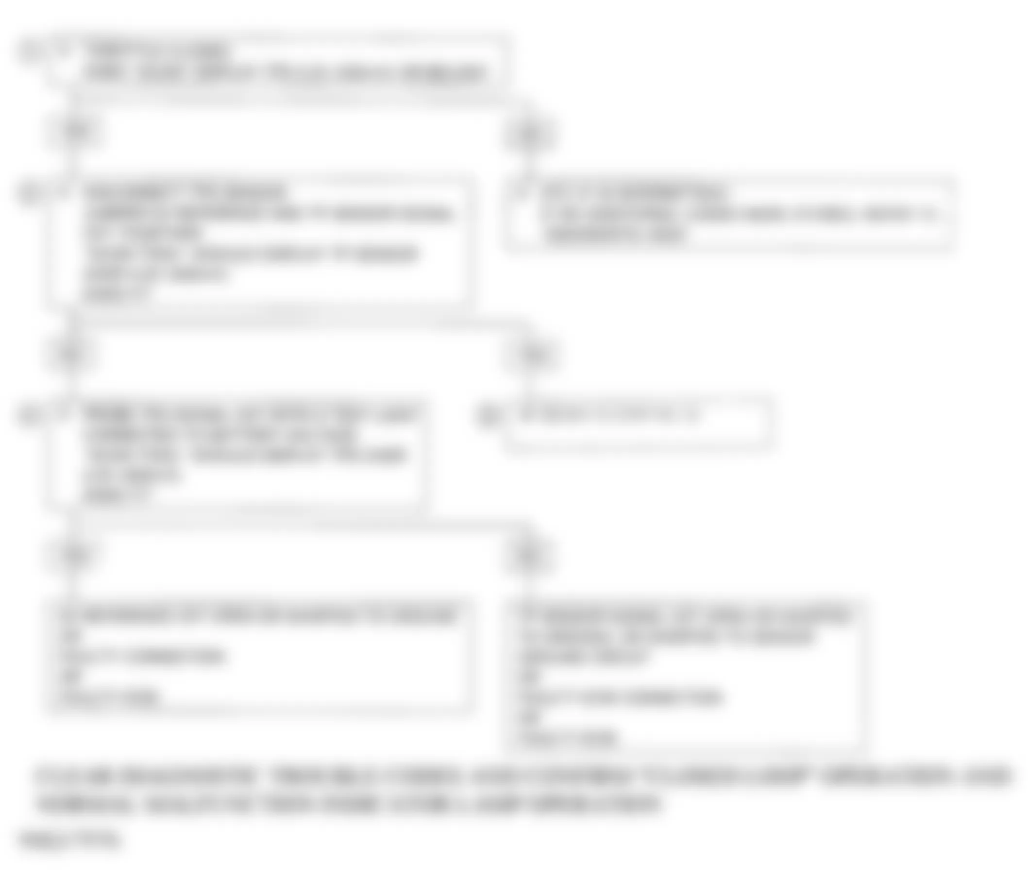
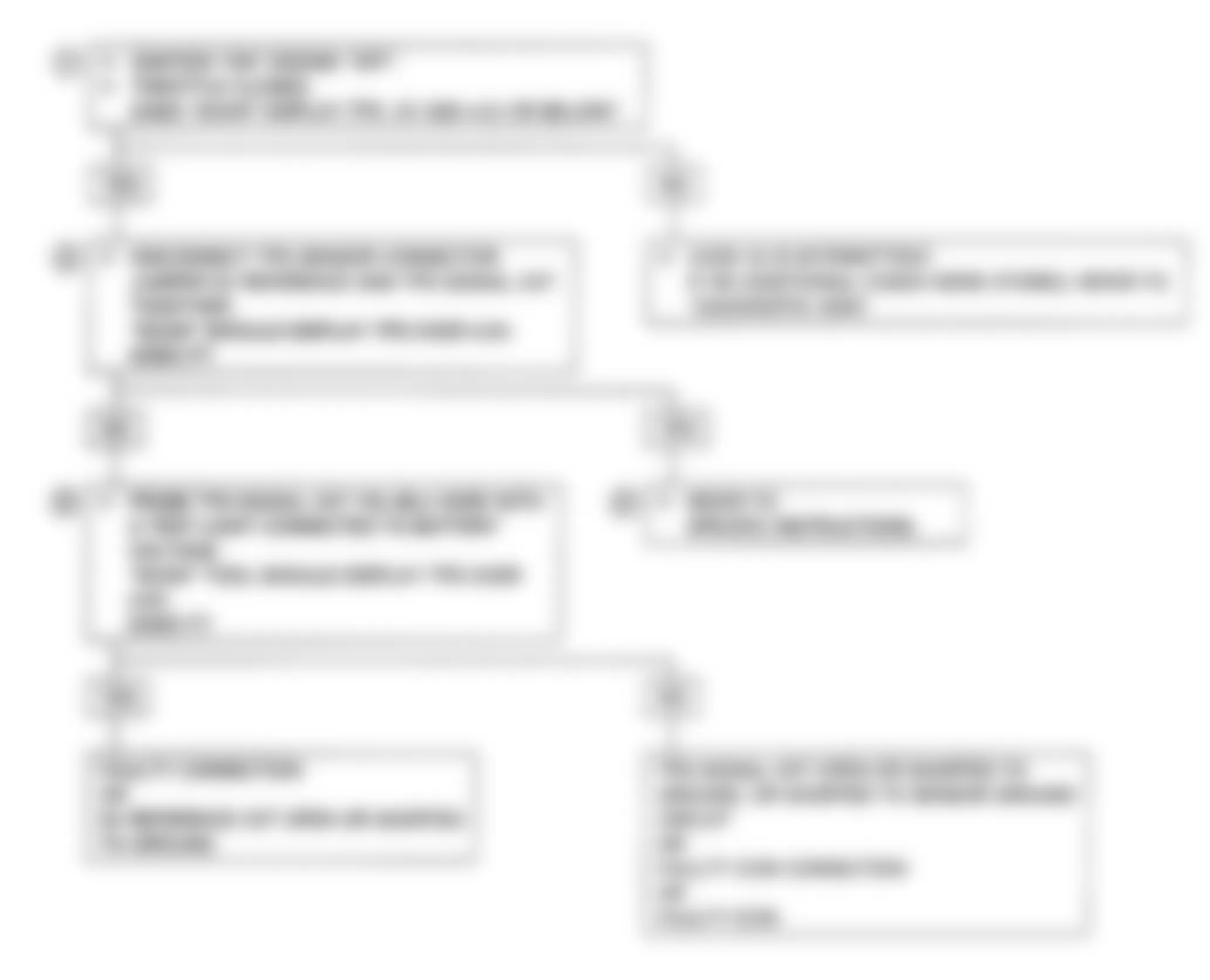
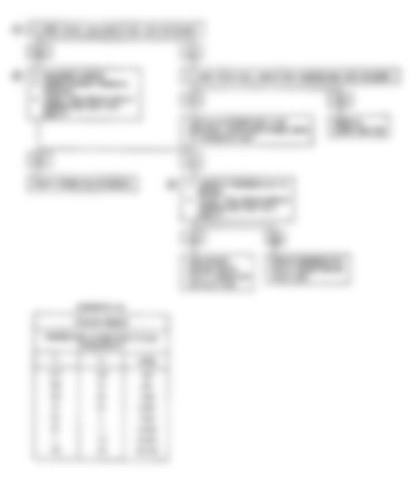
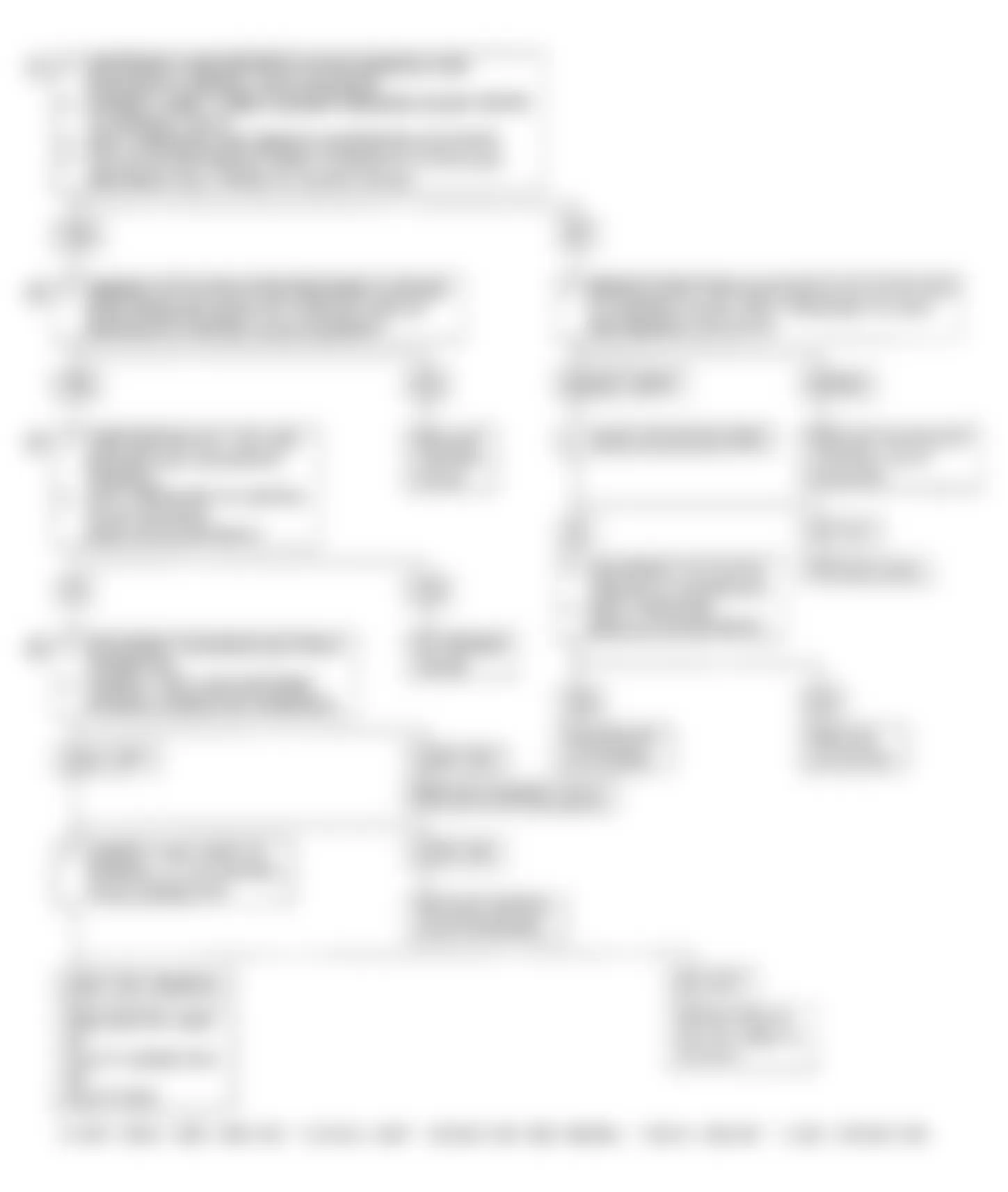
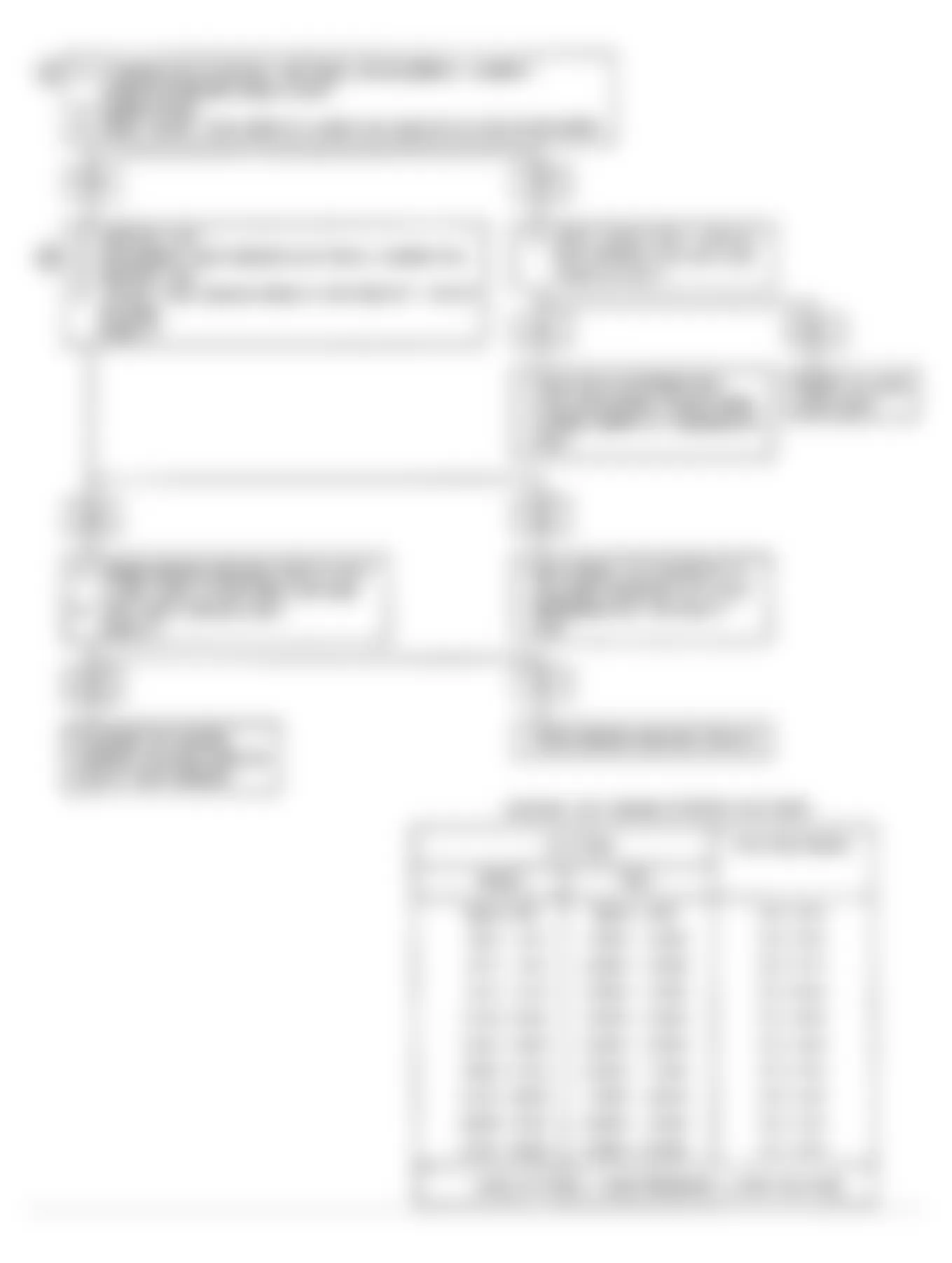
Isuzu Stylus XS 1991 - CHART A-2, NO ALDL DATA OR WON'T FLASH CODE 12 (TURBO) (CHECK ENGINE LIGHT ON STEADY)
There should always be a steady CHECK ENGINE light when ignition is on and engine off. Battery voltage is supplied to the bulb by the ECM, which activates the light by grounding Purple wire. With diagnostic terminal grounded, light should flash a Code 12, followed by any trouble codes stored in memory. A steady light could be a short to ground in the light control circuit (Purple wire), or an open in diagnostic circuit (Orange/Yellow wire).
NOTE: Test numbers refer to test numbers on diagnostic chart.
- If a problem exists with the ECM that causes a Scan tester not to read serial data, ECM should NOT flash a Code 12. If Code 12 does flash, ensure Scan tester is working properly on another vehicle. If Scan tester is functioning properly and Orange/Black wire is okay, the ECM may be at fault.
- If light goes off when ECM connector is disconnected, Purple wire is NOT shorted to ground.
- This tests for an open in Orange/Yellow wire.
- At this point, CHECK ENGINE light wiring is okay. The problem is a faulty ECM. If Code 12 does not flash, replace ECM.
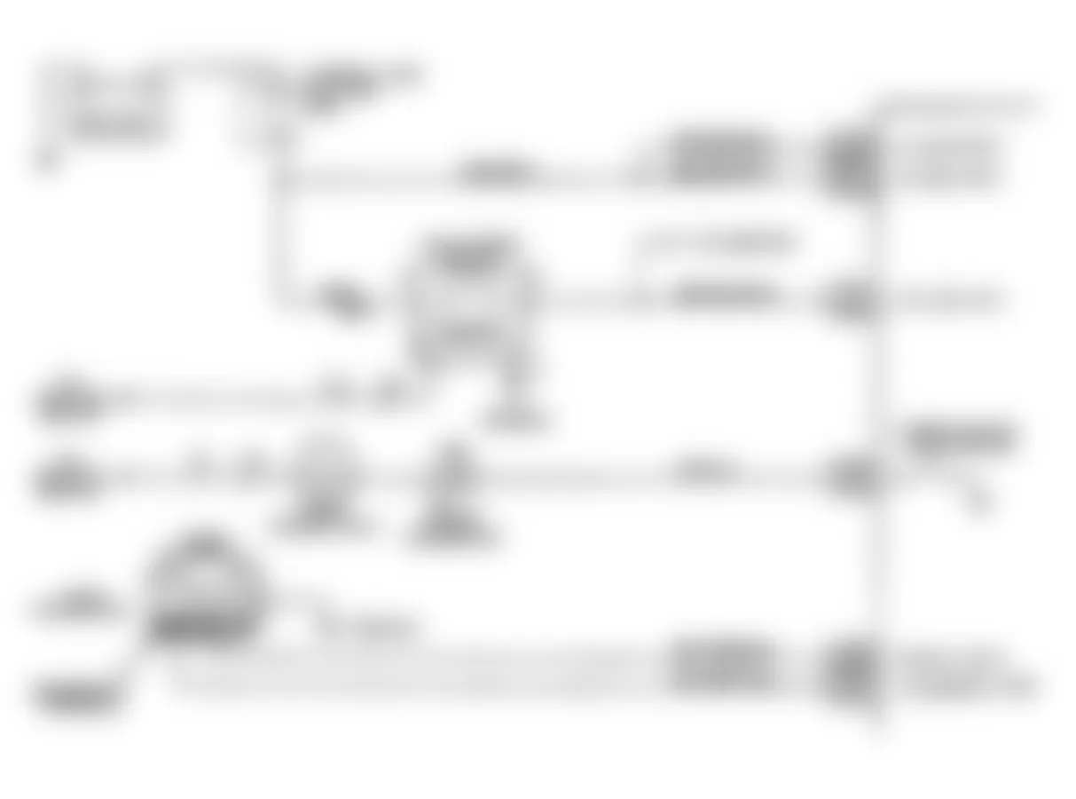
Fig. 13: Isuzu Stylus XS 1991 - Component Locations - Chart A-2 Circuit Diagram-No ALDL Data (Turbo)
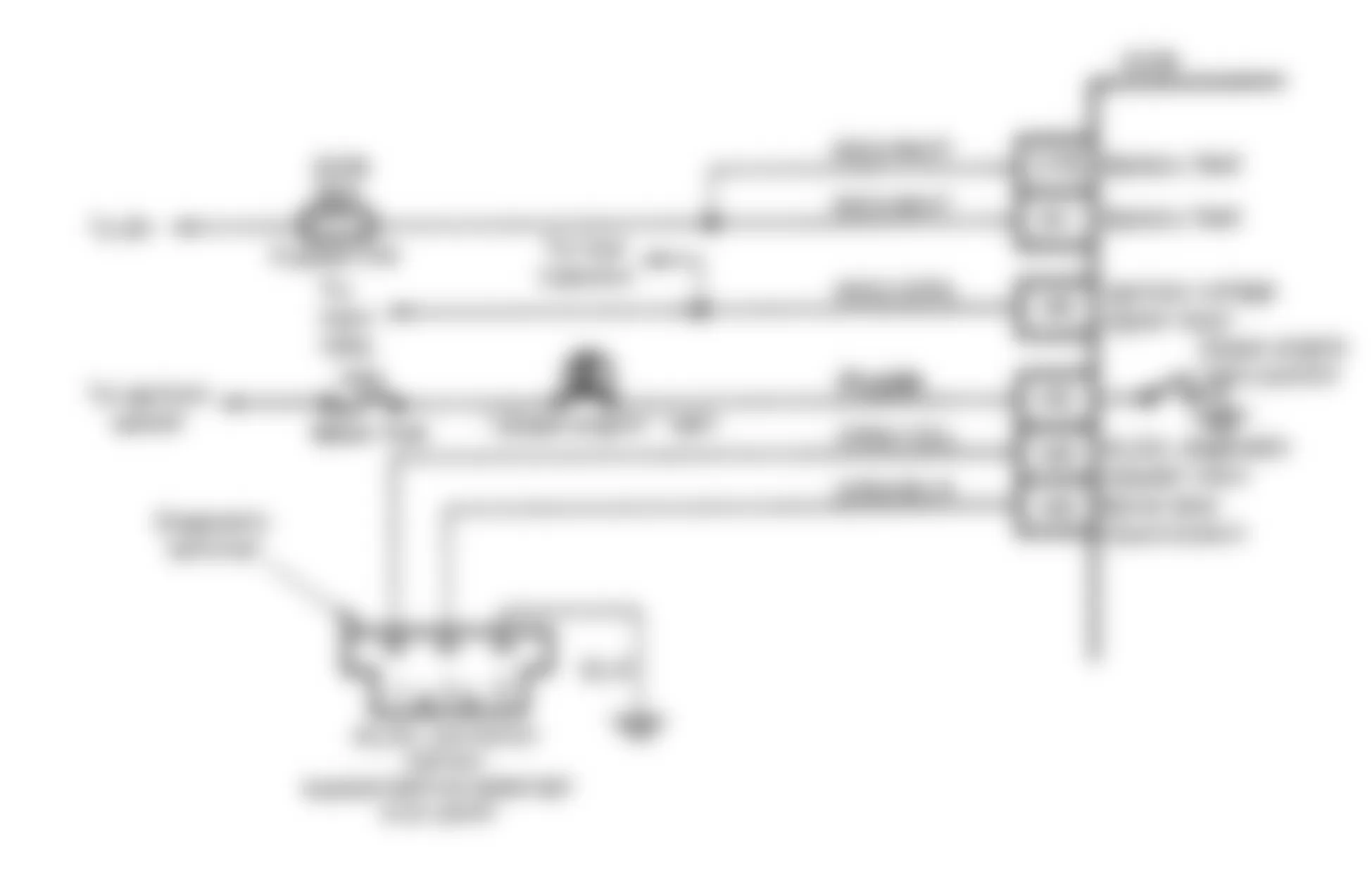
Fig. 14: Isuzu Stylus XS 1991 - Component Locations - Chart A-2 Flow Chart-No ALDL Data (Turbo)
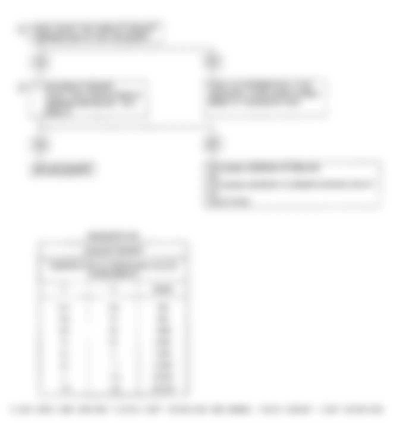
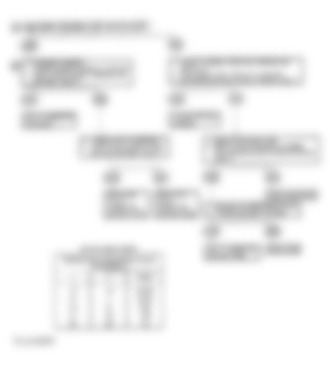
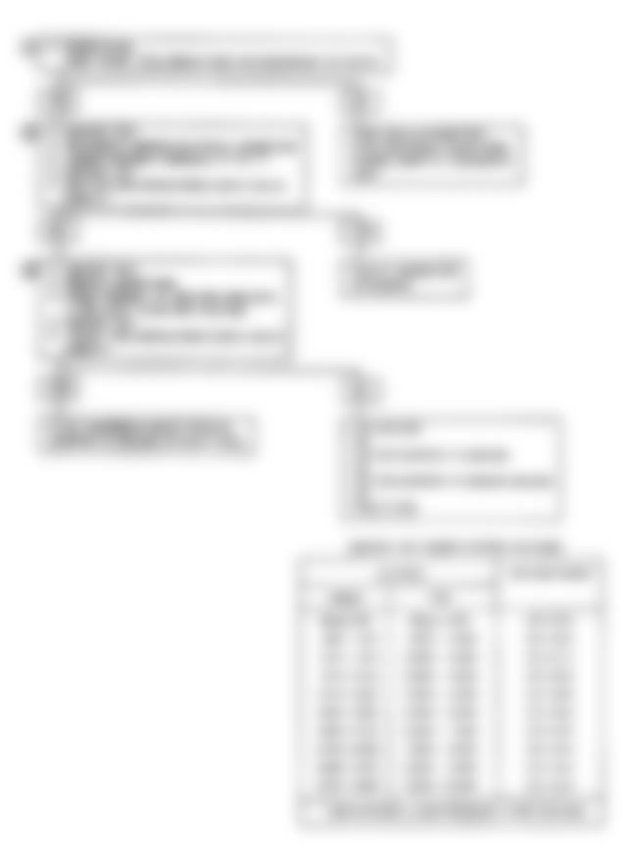
Isuzu Stylus XS 1991 - CODE 13: O2 SENSOR-OPEN/SHORTED CKT (DOHC NON-TURBO)
The ECM supplies a .45 volt signal between terminals D6 and D7. When oxygen sensor reaches operating temperature, it varies this voltage from approximately .1-.9 volt (lean to rich exhaust). Oxygen sensor does not produce voltage when temperature is less than 600?F (360?C) or when engine operates in open loop.
NOTE: Test numbers refer to test numbers on diagnostic chart.
- Code 13 will set if all the following conditions are met for 40 seconds:
- Engine temperature is greater than 157?F (69?C).
- Engine has been running for at least 50 seconds after start.
- O2 signal voltage steady between 0-.347 volt or steady above .547 volt.
- Throttle angle greater than 5 percent.
If conditions for Code 13 exist, system will not go into closed loop.
- This determines if sensor, wiring or ECM is the cause of Code 13.
- Use only a high impedance (10-megohm) digital volt/ohmmeter. This tests continuity of circuits No. 412 and 450. If circuit No. 450 is open, ECM voltage on circuit No. 412 will be greater than .6 volt.
Isuzu Stylus XS 1991 - Diagnostic Aids
Normal Scan tester voltage varies between .1-1.0 volts while in closed loop. Code 13 sets after approximately one minute if voltage remains between 0 and .35 volt, but system will enter open loop in approximately 15 seconds. For intermittent inspection, see INTERMITTENTS in H - EFI TESTS W/O CODES article in the ENGINE PERFORMANCE Section.

Fig. 16: Isuzu Stylus XS 1991 - Component Locations - Code 13 Flow Chart-O2 Sensor (DOHC Non-Turbo)

Isuzu Stylus XS 1991 - CODE 13: O2 SENSOR-OPEN/SHORTED CKT (TURBO)
The ECM supplies a .45 volt signal between terminals D6 and D7. When oxygen sensor reaches operating temperature, it varies this voltage from approximately .1-.9 volt (lean to rich exhaust). Oxygen sensor does not produce voltage when temperature is less than 600?F (360?C) or when engine operates in open loop.
NOTE: Test numbers refer to test numbers on diagnostic chart.
- Code 13 will set if all the following conditions are met for 4 seconds:
- Engine temperature is greater than 157?F (69?C).
- Engine has been running for at least 2 minutes after start.
- O2 signal voltage steady between .347 and .547 volt.
- Throttle angle greater than 10 percent.
If conditions for Code 13 exist, system will not go into closed loop.
- This determines if sensor, wiring or ECM is the cause of Code 13.
- Use only a high impedance (10-megohm) digital volt/ohmmeter. This tests continuity of circuits from terminals D6 and D7. If circuit from terminal D6 is open, ECM voltage on circuit from terminal D7 will be greater than .6 volt.
Fig. 17: Isuzu Stylus XS 1991 - Component Locations - Code 13 Circuit Diagram-O2 Sensor (Turbo)

Fig. 18: Isuzu Stylus XS 1991 - Component Locations - Code 13 Flow Chart-O2 Sensor (Turbo)
Isuzu Stylus XS 1991 - Diagnostic Aids
Normal Scan tester voltage varies between .1-1.0 volts while in closed loop. Code 13 sets after approximately one minute if voltage remains between .347 and .547 volt, but system will enter open loop in approximately 15 seconds. For intermittent inspection, see INTERMITTENTS in H - EFI TESTS W/O CODES article in the ENGINE PERFORMANCE Section.
Isuzu Stylus XS 1991 - CODE 13: O2 SENSOR-OPEN/SHORTED CKT (SOHC)
The ECM supplies a .45 volt signal between terminals D6 and D7. When oxygen sensor reaches operating temperature, it varies this voltage from approximately .1-.9 volt (lean to rich exhaust). Oxygen sensor does not produce voltage when temperature is less than 600?F (360?C) or when engine operates in open loop.
NOTE: Test numbers refer to test numbers on diagnostic chart.
- Code 13 will set if all the following conditions are met for 40 seconds:
- Engine temperature is greater than 157?F (69?C).
- Engine has been running for at least 5 minutes after start.
- O2 signal voltage steady between .35 and .55 volt.
- Throttle angle greater than 5 percent.
If conditions for Code 13 exist, system will not go into closed loop.
- This determines if sensor, wiring or ECM is the cause of Code 13.
- Use only a high impedance (10-megohm) digital volt/ohmmeter. This tests continuity of circuits No. 412 and 413. If circuit No. 413 is open, ECM voltage on circuit No. 412 will be greater than .6 volt.
Fig. 19: Isuzu Stylus XS 1991 - Component Locations - Code 13 Circuit Diagram-O2 Sensor (SOHC)

Fig. 20: Isuzu Stylus XS 1991 - Component Locations - Code 13 Flow Chart-O2 Sensor (SOHC)

Isuzu Stylus XS 1991 - Diagnostic Aids
Normal Scan tester voltage varies between .1-1.0 volts while in closed loop. Code 13 sets after approximately one minute if voltage remains between .35 and .55 volt, but system will enter open loop in approximately 15 seconds. For intermittent inspection, see INTERMITTENTS in H - EFI TESTS W/O CODES article in the ENGINE PERFORMANCE Section.
Isuzu Stylus XS 1991 - CODE 14: CTS CIRCUIT-HIGH TEMP INDICATED (TURBO)
Coolant temperature sensor uses a thermistor to control signal voltage to the ECM. The ECM applies voltage on Gray/Black wire to the sensor. When engine is cold, thermistor resistance is high and ECM will see a high signal voltage.
As engine warms, thermistor resistance is less and ECM will see a low signal voltage. When engine reaches normal operating temperature, signal voltage will be approximately 1.5-2.0 volts at ECM terminal C10. Coolant temperature is an input used by the ECM to control fuel delivery, Electronic Spark Control (EST) and idle air control.
NOTE: Test numbers refer to test numbers on diagnostic chart.
- This determines if code set because of a hard failure or an intermittent condition. Code 14 sets if signal voltage indicates a coolant temperature greater than 293?F (145?C) for 2 minutes.
- This simulates conditions for Code 15. If ECM sees open circuit (high voltage) and displays low coolant temperature, ECM and wiring are okay.
Isuzu Stylus XS 1991 - Diagnostic Aids
After engine is started, engine coolant temperature should rise to approximately 194?F (90?C) and stabilize when thermostat opens. If engine is allowed to cool overnight, coolant temperature and Manifold Air Temperature (MAT) should read nearly the same with a Scan tester. Code 14 results if Gray/Black wire is shorted to ground. For intermittent inspection, see INTERMITTENTS in H - EFI TESTS W/O CODES article in the ENGINE PERFORMANCE Section.
Isuzu Stylus XS 1991 COOLANT TEMP SENSOR RESISTANCE
Temp. ?F(?C) Ohms 210(100) 185 160(70) 450 100(38) 1800 70(20) 3400 40(4) 7500 20(-7) 13,500 0(-18) 25,000 -40(-40) 100,700
Fig. 21: Isuzu Stylus XS 1991 - Component Locations - Code 14 Circuit Diagram-CTS Circuit (Turbo)
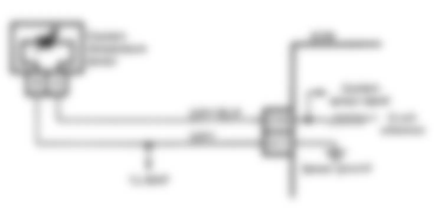
Fig. 22: Isuzu Stylus XS 1991 - Component Locations - Code 14 Flow Chart-CTS Circuit (Turbo)
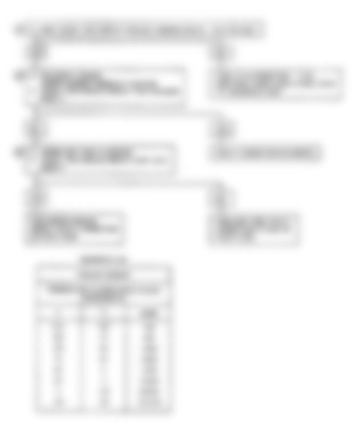
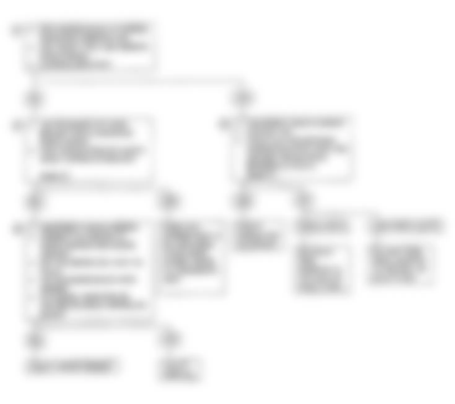
Isuzu Stylus XS 1991 - CODE 14A: CTS CKT-HIGH TEMP INDICATED (NON-TURBO)
Coolant temperature sensor uses a thermistor to control signal voltage to the ECM. The ECM applies voltage on Gray/Black wire to the sensor. When engine is cold, thermistor resistance is high and ECM will see a high signal voltage.
As engine warms, thermistor resistance is less and ECM will see a low signal voltage. When engine reaches normal operating temperature, signal voltage will be approximately 1.5-2.0 volts at ECM terminal No. A11. Coolant temperature is an input used by the ECM to control fuel delivery, Electronic Spark Control (EST) and cooling fan.
NOTE: Test numbers refer to test numbers on diagnostic chart.
- This determines if code set because of a hard failure or an intermittent condition. Code 14A sets if signal voltage indicates a coolant temperature greater than 275?F (135?C) for 3 seconds.
- This simulates conditions for Code 14B. If ECM sees open circuit (high voltage) and displays low coolant temperature, ECM and wiring are okay.
Isuzu Stylus XS 1991 - Diagnostic Aids
After engine is started, engine coolant temperature should rise to approximately 194?F (90?C) and stabilize when thermostat opens. If engine is allowed to cool overnight, coolant temperature and Manifold Air Temperature (MAT) should read nearly the same with a Scan tester. When Code 14A is set, the ECM turns on the cooling fan. Code 14A results if circuit No. 410 is shorted to ground. For intermittent inspection, see INTERMITTENTS in H - EFI TESTS W/O CODES article in the ENGINE PERFORMANCE Section.
Isuzu Stylus XS 1991 COOLANT TEMP SENSOR RESISTANCE
Temp. ?F(?C) Ohms 210(100) 185 160(70) 450 100(38) 1800 70(20) 3400 40(4) 7500 20(-7) 13,500 0(-18) 25,000 -40(-40) 100,700

Fig. 24: Isuzu Stylus XS 1991 - Component Locations - Code 14A Flow Chart-CTS Circuit (Non-Turbo)

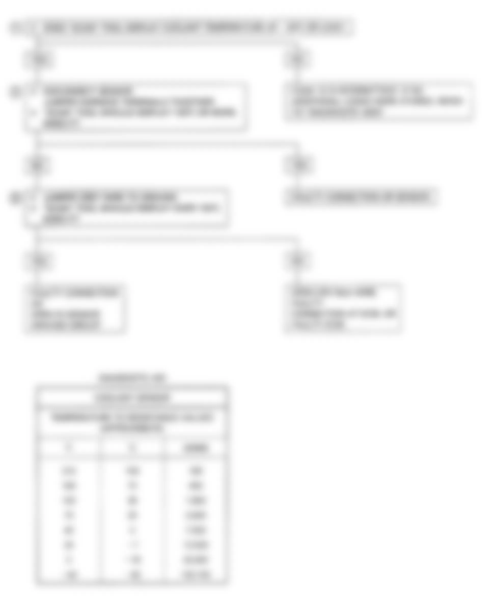
Isuzu Stylus XS 1991 - CODE 14B: CTS CKT-LOW TEMP INDICATED (NON-TURBO)
Coolant temperature sensor uses a thermistor to control signal voltage to the ECM. The ECM applies voltage on Gray/Black wire to the sensor. When engine is cold, thermistor resistance is high and ECM will see a high signal voltage.
As engine warms, thermistor resistance is less and ECM will see a low signal voltage. When engine reaches normal operating temperature, signal voltage will be approximately 1.5-2.0 volts at ECM terminal No. A11. Coolant temperature is an input used by the ECM to control fuel delivery, Electronic Spark Control (EST), idle speed and cooling fan.
NOTE: Test numbers refer to test numbers on diagnostic chart.
- This determines if code set because of a hard failure or an intermittent condition. Code 14B sets if signal voltage indicates a coolant temperature less than -22?F (-30?C) after engine has been running for 2 minutes.
- This simulates conditions for Code 14A. If ECM sees grounded circuit (low voltage) and displays high coolant temperature, the ECM and wiring are okay.
- This determines if wiring or ECM is faulty. If circuit No. 452 is open, a Code 33 may also be stored. Check for defective connection at Black engine harness connector.
Isuzu Stylus XS 1991 - Diagnostic Aids
After engine is started, engine coolant temperature should rise to approximately 194?F (90?C) and stabilize when thermostat opens. If engine is allowed to cool overnight, coolant temperature and Manifold Air Temperature (MAT) should read nearly the same with Scan tester. Code 14B results if circuit No. 410 or 452 is shorted to ground. For intermittent inspection, see INTERMITTENTS in H - EFI TESTS W/O CODES article in the ENGINE PERFORMANCE Section.
Isuzu Stylus XS 1991 COOLANT TEMP SENSOR RESISTANCE
Temp. ?F(?C) Ohms 210(100) 185 160(70) 450 100(38) 1800 70(20) 3400 40(4) 7500 20(-7) 13,500 0(-18) 25,000 -40(-40) 100,700

Fig. 26: Isuzu Stylus XS 1991 - Component Locations - Code 14B Flow Chart-CTS Circuit (Non-Turbo)
Isuzu Stylus XS 1991 - CODE 15: CTS CKT-LOW TEMP INDICATED (TURBO)
Coolant temperature sensor uses a thermistor to control signal voltage to the ECM. The ECM applies voltage on Gray/Black wire to the sensor. When engine is cold, thermistor resistance is high and ECM will see a high signal voltage.
As engine warms, thermistor resistance is less and ECM will see a low signal voltage. When engine reaches normal operating temperature, signal voltage will be approximately 1.5-2.0 volts at ECM terminal A11. Coolant temperature is an input used by the ECM to control fuel delivery, Electronic Spark Control (EST) and engine idle speed.
NOTE: Test numbers refer to test numbers on diagnostic chart.
- This determines if code set because of a hard failure or an intermittent condition. Code 15 sets if signal voltage indicates a coolant temperature less than -38?F (-39?C) after engine has been running for 1 minutes.
- This simulates conditions for Code 14. If ECM sees grounded circuit (low voltage) and displays high coolant temperature, the ECM and wiring are okay.
- This determines if wiring or ECM is faulty.
Isuzu Stylus XS 1991 - Diagnostic Aids
After engine is started, engine coolant temperature should rise to approximately 194?F (90?C) and stabilize when thermostat opens. If engine is allowed to cool overnight, coolant temperature and Manifold Air Temperature (MAT) should read nearly the same with Scan tester. Code 15 results if Gray wire or Gray/Black wire is shorted to ground. For intermittent inspection, see INTERMITTENTS in H - EFI TESTS W/O CODES article in the ENGINE PERFORMANCE Section.
Isuzu Stylus XS 1991 COOLANT TEMP SENSOR RESISTANCE
Temp. ?F(?C) Ohms 210(100) 185 160(70) 450 100(38) 1800 70(20) 3400 40(4) 7500 20(-7) 13,500 0(-18) 25,000 -40(-40) 100,700
Fig. 27: Isuzu Stylus XS 1991 - Component Locations - Code 15 Circuit Diagram-CTS Circuit (Turbo)

Fig. 28: Isuzu Stylus XS 1991 - Component Locations - Code 15 Flow Chart-CTS Circuit (Turbo)
Isuzu Stylus XS 1991 - CODE 21: TPS CKT-SIGNAL VOLTAGE HIGH (TURBO)
Throttle Position Sensor (TPS) provides a voltage signal which changes relative to throttle opening. Signal voltage varies from less than 1.25 volts at idle to approximately 5 volts at wide open throttle. The TPS signal is used by ECM for fuel control and most ECM controlled outputs.
NOTE: Test numbers refer to test numbers on diagnostic chart.
- This determines if Code 21 is from a hard failure or an intermittent condition. Code 21 will set if the following conditions are present for 5 seconds:
- TPS reading is greater than 4.7 volts.
- Engine speed is less than 1200 RPM.
- Map sensor vacuum reading is less than 9 in. Hg.
- This step simulates conditions for a Code 22. If ECM recognizes the change, the ECM and Yellow/Blue and Blue/Orange wires are okay.
- This step isolates a faulty sensor, ECM or an open in Black/White wire. If open is present in Black/White wire, Code 23 may also be present.
Isuzu Stylus XS 1991 - Diagnostic Aids
With throttle closed, TPS voltage should be less than 1.25 volts. TPS voltage should steadily increase as throttle is opened. Code 21 will result if Black/White wire is open or Blue/Red wire is shorted to voltage. For intermittent inspection, see INTERMITTENTS in H - EFI TESTS W/O CODES article in the ENGINE PERFORMANCE Section.
Fig. 29: Isuzu Stylus XS 1991 - Component Locations - Code 21 Circuit Diagram-TPS Circuit (Turbo)

Fig. 30: Isuzu Stylus XS 1991 - Component Locations - Code 21 Flow Chart-TPS Circuit (Turbo)
Isuzu Stylus XS 1991 - CODE 21A: TPS CKT-SIGNAL VOLTAGE HIGH (NON-TURBO)
Throttle Position Sensor (TPS) provides a voltage signal which changes relative to throttle opening. Signal voltage varies from less than .9 volt at idle to approximately 4.5 volts at wide open throttle. The TPS signal is used by ECM for fuel control and most ECM controlled outputs.
NOTE: Test numbers refer to test numbers on diagnostic chart.
- This determines if Code 21A is from a hard failure or an intermittent condition. Code 21A will set if the following conditions are present for 2 seconds:
- TPS reading is greater than 2.5 volts.
- Engine speed is less than 1800 RPM.
- MAP sensor vacuum reading is less than 9 in. Hg.
- This step simulates conditions for a Code 21B. If ECM recognizes the change, the ECM and circuits No. 416 and 417 are okay.
- This step isolates a faulty sensor, ECM or an open in circuit No. 452. If open is present in circuit No. 452, Code 23A may also be present.
Isuzu Stylus XS 1991 - Diagnostic Aids
With throttle closed, TPS voltage should be less than 1.25 volts. TPS voltage should steadily increase as throttle is opened. Code 21A will result if circuit No. 452 is open or circuit No. 417 is shorted to voltage. For intermittent inspection, see INTERMITTENTS in H - EFI TESTS W/O CODES article in the ENGINE PERFORMANCE Section.
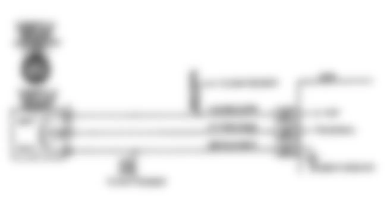
Fig. 32: Isuzu Stylus XS 1991 - Component Locations - Code 21A Flow Chart-TPS Circuit (Non-Turbo)
Isuzu Stylus XS 1991 - CODE 21B: TPS CKT-SIGNAL VOLTAGE LOW (NON-TURBO)
Throttle Position Sensor (TPS) provides a voltage signal which changes relative to throttle opening. Signal voltage varies from less than .9 volt at idle to approximately 4.5 volts at wide open throttle. The TPS signal is used by ECM for fuel control and most ECM controlled outputs.
NOTE: Test numbers refer to test numbers on diagnostic chart.
- This determines if Code 21B is from a hard failure or an intermittent condition. Code 21B will set if engine is running and TPS reading is less than .2 volt (200 mV).
- This step simulates conditions for a Code 21A. If Code 21A is set, or Scan tester displays greater than 4 volts, ECM and wiring are okay.
- Scan tester may not display 12 volts, but ECM recognizes the voltage as greater than 4 volts, indicating that circuit No. 417 and ECM are okay.
- If circuit No. 416 is open or shorted to ground, a Code 33B may also be stored.
Isuzu Stylus XS 1991 - Diagnostic Aids
With throttle closed, TPS voltage should be less than 1.25 volts. TPS voltage should steadily increase as throttle is opened. Code 21B will result if circuit No. 416 or 417 is open or grounded. For intermittent inspection, see INTERMITTENTS in H - EFI TESTS W/O CODES article in the ENGINE PERFORMANCE Section.

Fig. 34: Isuzu Stylus XS 1991 - Component Locations - Code 21B Flow Chart-TPS Circuit (Non-Turbo)
Isuzu Stylus XS 1991 - CODE 22: TPS CKT-SIGNAL VOLTAGE LOW (TURBO)
Throttle Position Sensor (TPS) provides a voltage signal which changes relative to throttle opening. Signal voltage varies from less than 1.25 volts at idle to approximately 5 volts at wide open throttle. The TPS signal is used by ECM for fuel control and most ECM controlled outputs.
NOTE: Test numbers refer to test numbers on diagnostic chart.
- This determines if Code 22 is from a hard failure or an intermittent condition. Code 22 will set if engine is running and TPS reading is less than .2 volt (200 mV).
- This step simulates conditions for a Code 21. If Code 21 is set, or Scan tester displays greater than 4 volts, ECM and wiring are okay.
- Scan tester may not display 12 volts, but ECM recognizes the voltage as greater than 4 volts, indicating that Yellow/Blue wire and ECM are okay.
- If Blue/Orange wire is open or shorted to ground, a Code 33 may also be stored.
Isuzu Stylus XS 1991 - Diagnostic Aids
With throttle closed, TPS voltage should be less than 1.25 volts. TPS voltage should steadily increase as throttle is opened. Code 22 will result if Blue/Orange wire or Yellow/Blue wire is open or grounded. For intermittent inspection, see INTERMITTENTS in H - EFI TESTS W/O CODES article in the ENGINE PERFORMANCE Section.
Fig. 35: Isuzu Stylus XS 1991 - Component Locations - Code 22 Circuit Diagram-TPS Circuit (Turbo)
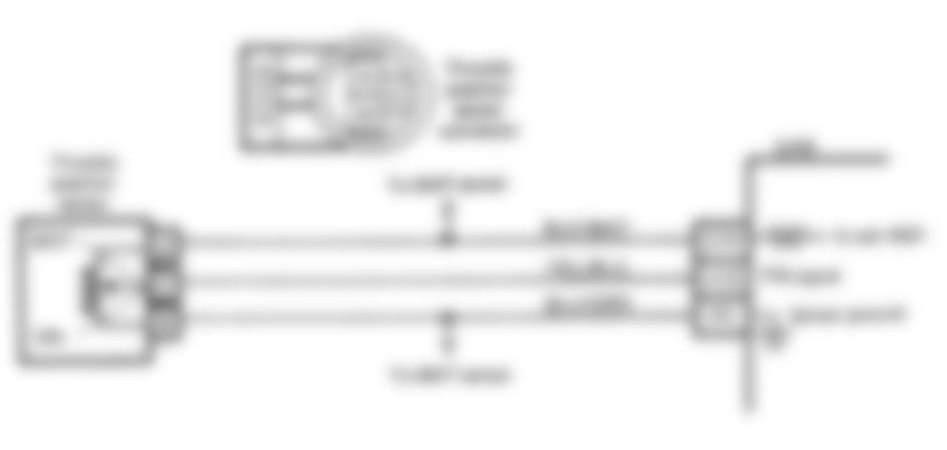
Fig. 36: Isuzu Stylus XS 1991 - Component Locations - Code 22 Flow Chart-TPS Circuit (Turbo)
Isuzu Stylus XS 1991 - CODE 23: MAT SENSOR CKT-LOW TEMP INDICATED (TURBO)
The MAT sensor uses a thermistor to control signal voltage to the ECM. The ECM applies 4-6 volts on Blue/Black wire to MAT sensor. When manifold air is cold, sensor resistance is high and ECM will see a high voltage. As air temperature increases, sensor resistance decreases and the voltage drops.
NOTE: Test numbers refer to test numbers on diagnostic chart.
- This determines if Code 23 is result of a hard failure or an intermittent condition. Code 23 will set if engine is running longer than 1 minute and signal voltage indicates a MAT temperature below -38?F (-39?C).
- This step simulates conditions for a Code 25. If Scan tester displays a high temperature, ECM and wiring are okay.
- This step checks continuity of Blue/Black wire and Black/White wire. If Black/White wire is open, a Code 22 may be present.
Isuzu Stylus XS 1991 - Diagnostic Aids
If engine is allowed to cool overnight, coolant temperature and Manifold Air Temperature (MAT) should read nearly the same with Scan tester. A Code 23 results if an open is present in Blue/Black wire or Black/White wire. For intermittent inspection, see INTERMITTENTS in H - EFI TESTS W/O CODES article in the ENGINE PERFORMANCE Section.
Isuzu Stylus XS 1991 MAT SENSOR RESISTANCE
Temp. ?F(?C) Ohms 210(100) 185 160(70) 450 100(38) 1800 70(20) 3400 40(4) 7500 20(-7) 13,500 0(-18) 25,000 -40(-40) 100,700

Fig. 38: Isuzu Stylus XS 1991 - Component Locations - Code 23 Flow Chart-MAT Sensor Circuit (Turbo)
Isuzu Stylus XS 1991 - CODE 23A: MAT SENSOR CKT-LOW TEMP INDICATED (NON-TURBO)
The MAT sensor uses a thermistor to control signal voltage to the ECM. The ECM applies 4-6 volts on circuit No. 472 to MAT sensor. When manifold air is cold, sensor resistance is high and ECM will see a high voltage. As air temperature increases, sensor resistance decreases and the voltage drops.
NOTE: Test numbers refer to test numbers on diagnostic chart.
- This determines if Code 23A is result of a hard failure or an intermittent condition. Code 23A will set if engine is running longer than 2 minutes and signal voltage indicates a MAT temperature below -22?F (-30?C).
- This step simulates conditions for a Code 23B. If Scan tester displays a high temperature, ECM and wiring are okay.
- This step checks continuity of circuits No. 452 and 472. If circuit No. 452 is open, a Code 21A may be present.
Isuzu Stylus XS 1991 - Diagnostic Aids
If engine is allowed to cool overnight, coolant temperature and Manifold Air Temperature (MAT) should read nearly the same with Scan tester. A Code 23A results if an open is present in circuit No. 452 or 472. For intermittent inspection, see INTERMITTENTS in H - EFI TESTS W/O CODES article in the ENGINE PERFORMANCE Section.
Isuzu Stylus XS 1991 MAT SENSOR RESISTANCE
Temp. ?F(?C) Ohms 210(100) 185 160(70) 450 100(38) 1800 70(20) 3400 40(4) 7500 20(-7) 13,500 0(-18) 25,000 -40(-40) 100,700

Isuzu Stylus XS 1991 - CODE 23B: MAT SENSOR CKT-HIGH TEMP INDICATED (NON-TURBO)
The MAT sensor uses a thermistor to control signal voltage to the ECM. The ECM applies 4-6 volts on circuit No. 472 to MAT sensor. When manifold air is cold, sensor resistance is high and ECM will see a high voltage. As air temperature increases, sensor resistance decreases and the voltage drops.
NOTE: Test numbers refer to test numbers on diagnostic chart.
- This determines if Code 23B is the result of a hard failure or an intermittent condition. Code 23B will set if MAT temperature is indicated to be greater than 275?F (135?C) for more than 2 seconds.
Isuzu Stylus XS 1991 - Diagnostic Aids
If engine is allowed to cool overnight, coolant temperature and Manifold Air Temperature (MAT) should read nearly the same with Scan tester. A Code 23B results if circuit No. 452 or 472 becomes open or shorted to ground. For intermittent inspection, see INTERMITTENTS in TESTS W/O CODES article in the ENGINE PERFORMANCE Section.
Isuzu Stylus XS 1991 MAT SENSOR RESISTANCE
Temp. ?F(?C) Ohms 210(100) 185 160(70) 450 100(38) 1800 70(20) 3400 40(4) 7500 20(-7) 13,500 0(-18) 25,000 -40(-40) 100,700


Isuzu Stylus XS 1991 - CODE 24: 1.6L VSS CIRCUIT
The ECM provides battery voltage to the Vehicle Speed Sensor (VSS), located behind instrument panel. The VSS alternately grounds circuit No. 347, which toggles the voltage high and low. This pulsed signal is used by the ECM to determine vehicle speed.
NOTE: Test numbers refer to test numbers on diagnostic chart.
- Code 24 sets if vehicle speed equals 0 MPH when:
- Engine speed is between 1500-4400 RPM.
- TPS is at zero percent (closed throttle).
- MAP reads low voltage with high vacuum (low load condition).
- Transaxle not in Park or Neutral.
- Speed sensor indicates speeds less than 5 MPH.
- All conditions are met for 3 seconds.
These conditions are met during a road load deceleration. Disregard Code 24 that sets when drive wheels are not operating.
Isuzu Stylus XS 1991 - Diagnostic Aids
Scan tester should indicate a vehicle speed whenever the drive wheels are turning faster than 3 MPH. Check circuit No. 437 for proper connections. Ensure wire connector is clean and tight and harness is routed correctly. A problem in circuit No. 437 will not affect the VSS input or Scan tester readings. For intermittent inspection, see INTERMITTENTS in H - EFI TESTS W/O CODES article in the ENGINE PERFORMANCE Section.
Fig. 43: Isuzu Stylus XS 1991 - Component Locations - Code 24 Circuit Diagram-VSS Circuit

Fig. 44: Isuzu Stylus XS 1991 - Component Locations - Code 24 Flow Chart-VSS Circuit
Isuzu Stylus XS 1991 - CODE 25: MAT SENSOR CKT-HIGH TEMP INDICATED (TURBO)
The MAT sensor uses a thermistor to control signal voltage to the ECM. The ECM applies 4-6 volts on Blue/Black wire to MAT sensor. When manifold air is cold, sensor resistance is high and ECM will see a high voltage. As air temperature increases, sensor resistance decreases and the voltage drops.
NOTE: Test numbers refer to test numbers on diagnostic chart.
- This determines if Code 25 is the result of a hard failure or an intermittent condition. Code 25 will set if MAT temperature is greater than 293?F (145?C) for more than 2 minutes.
Isuzu Stylus XS 1991 - Diagnostic Aids
If engine is allowed to cool overnight, coolant temperature and Manifold Air Temperature (MAT) should read nearly the same with Scan tester. A Code 25 results if Blue/Black wire or Black/White wire becomes open or shorted to ground. For intermittent inspection, see INTERMITTENTS in H - EFI TESTS W/O CODES article in the ENGINE PERFORMANCE Section.
Isuzu Stylus XS 1991 MAT SENSOR RESISTANCE
Temp. ?F(?C) Ohms 210(100) 185 160(70) 450 100(38) 1800 70(20) 3400 40(4) 7500 20(-7) 13,500 0(-18) 25,000 -40(-40) 100,700
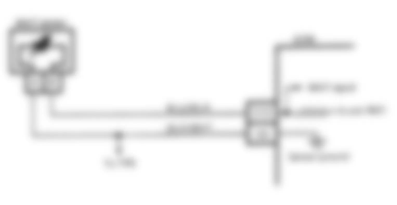
Fig. 46: Isuzu Stylus XS 1991 - Component Locations - Code 25 Flow Chart-MAT Sensor Circuit (Turbo)
Isuzu Stylus XS 1991 - CODE 31: TURBO OVERBOOST (TURBO)
On turbocharged engines, exhaust gases pass from exhaust manifold through turbocharger, turning turbine blades. Compressor side of turbocharger also turns, pulling air through air filter and pushing it into intake manifold under pressure.
Wastegate is normally closed, but will open to allow by-pass of exhaust gases when an overboost condition exists. This is determined through monitored MAP sensor signals. Under normal driving conditions, ECM energizes the wastegate control (solenoid) valve. This blocks off intake manifold pressure from wastegate actuator diaphragm. When overboost condition exists, ECM will de-energize the wastegate control (solenoid) valve, allowing intake manifold pressure to act upon actuator diaphragm, opening wastegate.
As boost pressure decreases, ECM energizes wastegate control (solenoid) valve which causes wastegate to close. If MAP sensor indicates that an overboost condition exists, ECM will cut fuel delivery to prevent engine damage.
NOTE: Test numbers refer to test numbers on diagnostic chart.
- Code 31 will set when Code 33 is not set and excessive manifold boost pressure is sensed for 2 seconds. Code 31 will be set, but CHECK ENGINE LIGHT will stay on only while overboost condition exists and for 10 seconds after manifold boost pressure has been reduced. Code 31 may be caused by White/Purple wire shorted to ground, a sticking wastegate or actuator, control (solenoid) valve stuck in the closed position, a cut or pinched hose, an extremely dirty air filter or a faulty ECM.
- After pressure is applied to valve and then removed, actuator should slowly close wastegate. If pressure does not bleed off, vent in control (solenoid) valve could be plugged.
- With ignition on and ALDL test terminal "B" grounded, control (solenoid) valve should be energized. This closes off the manifold vacuum to the wastegate actuator.
- This checks the electrical control portion of the system. With ignition on and engine not running, solenoid should not be energized.

Fig. 48: Isuzu Stylus XS 1991 - Component Locations - Code 31 Flow Chart-Turbo Overboost (Turbo)
Isuzu Stylus XS 1991 - CODE 32: 1.6L EXHAUST GAS RECIRCULATION (EGR) CIRCUIT
ECM controls a solenoid that regulates vacuum to the EGR valve. EGR control solenoid is cycled by ECM grounding White/Green wire. ECM calculates EGR control solenoid duty cycle using information from CTS and TPS. EGR control solenoid is energized when diagnostic terminal is grounded.
NOTE: Test numbers refer to test numbers on diagnostic chart.
- With engine at normal operating temperature, Code 32 will set if the difference of EGR gas temperature between EGR on and EGR off is less than 37?F (3?C) or if signal voltage indicates an EGR gas temperature greater than 662?F (350?C) or less than -33?F (-36?C).
- Determines if problem is with EGR valve, EGR gas temperature sensor, ECM or wiring.
Isuzu Stylus XS 1991 - Diagnostic Aids
With engine running and EGR off, EGR gas temperature should be close to manifold air temperature. With EGR on, EGR gas temperature should be 212-482?F (100-250?C).
Isuzu Stylus XS 1991 EGR GAS TEMP SENSOR RESISTANCE
Temp. ?F(?C) Ohms -40(-40) 200,000 32(0) 28,000 104(40) 5800 212(100) 1000 392(200) 135
Fig. 49: Isuzu Stylus XS 1991 - Component Locations - Code 32 Circuit Diagram-EGR Circuit
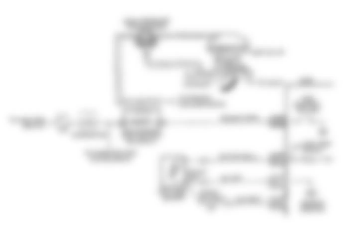
Fig. 50: Isuzu Stylus XS 1991 - Component Locations - Code 32 Flow Chart-EGR Circuit
Isuzu Stylus XS 1991 - CODE 33: MAP SENSOR-SIGNAL VOLTAGE HIGH/LOW VAC (TURBO)
The MAP sensor responds to changes in manifold vacuum. The ECM receives a signal voltage from MAP sensor varying from .53-.61 volt at idle (closed throttle) to 2.18-4.28 volts at wide open throttle. If MAP sensor fails, ECM will substitute a fixed MAP value and use the TPS input to control fuel delivery.
NOTE: Test numbers refer to test numbers on diagnostic chart.
- This determines if Code 33 is the result of a hard failure or an intermittent condition. Code 33 will set if the following conditions are present for 15 seconds:
- MAP signal indicates low vacuum.
- No Code 21, 22 or 31 is set.
- TPS is less than 1 percent.
- This step simulates conditions for a Code 34. If ECM recognizes the change, the ECM and Gray wire and Gray/Red wire are okay. If Blue/Orange wire is open, Code 22 may be stored.
Isuzu Stylus XS 1991 - Diagnostic Aids
With ignition on and engine off, manifold pressure is equal to atmospheric pressure and signal voltage will be high. This information is used by ECM as an indication of vehicle altitude and is referred to as BARO. To check sensor, compare BARO reading with a known good vehicle with the same sensor. Readings should be the same within .4 volt.
Code 33 results if Gray wire is open, or if Gray/Red wire is shorted to voltage or Blue/Orange wire. For intermittent inspection, see INTERMITTENTS in H - EFI TESTS W/O CODES article in the ENGINE PERFORMANCE Section.
Isuzu Stylus XS 1991 MAP SENSOR VOLTAGE (1)
Altitude Meters Altitude Feet (2) Voltage Range Below 305 Below 1000 3.8-5.5V 305-610 1000-2000 3.6-5.3V 610-914 2000-3000 3.5-5.1V 914-1219 3000-4000 3.3-5.0V 1219-1524 4000-5000 3.2-4.8V 1524-1829 5000-6000 3.0-4.6V 1829-2133 6000-7000 2.9-4.5V 2133-2438 7000-8000 2.8-4.3V 2483-2743 8000-9000 2.6-4.2V 2743-3048 9000-10,000 2.5-4.0V
(1) Low Altitude = High Pressure = High Voltage
(2) Voltage reading taken with key on/engine off

Fig. 52: Isuzu Stylus XS 1991 - Component Locations - Code 33 Flow Chart-MAP Sensor Circuit (Turbo)
Isuzu Stylus XS 1991 - CODE 33A: MAP SENSOR-VOLTAGE HIGH/LOW VAC (NON-TURBO)
The MAP sensor responds to changes in manifold vacuum. The ECM receives a signal voltage from MAP sensor varying from 1-1.5 volts at idle (closed throttle) to 4.5 volts at wide open throttle. If MAP sensor fails, ECM will substitute a fixed MAP value and use the TPS input to control fuel delivery.
NOTE: Test numbers refer to test numbers on diagnostic chart.
- This determines if Code 33A is the result of a hard failure or an intermittent condition. Code 33A will set if the following conditions are present for more than 5 seconds:
- MAP signal indicates low vacuum.
- No Code 21A or 21B is set.
- TPS is less than 5 percent.
- This step simulates conditions for a Code 33B. If ECM recognizes the change, the ECM and circuits No.416 and 432 are okay. If circuit No. 452 is open, Code 21A may be stored.
Isuzu Stylus XS 1991 - Diagnostic Aids
With ignition on and engine off, manifold pressure is equal to atmospheric pressure and signal voltage will be high. This information is used by ECM as an indication of vehicle altitude and is referred to as BARO. To check sensor, compare BARO reading with a known good vehicle with the same sensor. Readings should be the same within .4 volt.
Code 33A results if circuit No. 452 is open or if circuit No. 432 is shorted to either voltage or circuit No. 416. For intermittent inspection, see INTERMITTENTS in H - EFI TESTS W/O CODES article in the ENGINE PERFORMANCE Section.
Isuzu Stylus XS 1991 MAP SENSOR VOLTAGE (1)
Altitude Meters Altitude Feet (2) Voltage Range Below 305 Below 1000 3.8-5.5V 305-610 1000-2000 3.6-5.3V 610-914 2000-3000 3.5-5.1V 914-1219 3000-4000 3.3-5.0V 1219-1524 4000-5000 3.2-4.8V 1524-1829 5000-6000 3.0-4.6V 1829-2133 6000-7000 2.9-4.5V 2133-2438 7000-8000 2.8-4.3V 2483-2743 8000-9000 2.6-4.2V 2743-3048 9000-10,000 2.5-4.0V
(1) Low Altitude = High Pressure = High Voltage
(2) Voltage reading taken with key on/engine off

Isuzu Stylus XS 1991 - CODE 33B: MAP SENSOR-VOLTAGE LOW/HIGH VAC (NON-TURBO)
The MAP sensor responds to changes in manifold pressure (vacuum). The ECM receives a signal voltage from MAP sensor varying from .5-2.0 volts at idle (closed throttle) to 4-5 volts at wide open throttle. If MAP sensor fails, ECM will substitute a fixed MAP value and use TPS input to control fuel delivery.
NOTE: Test numbers refer to test numbers on diagnostic chart.
- This determines if Code 33B is result of a hard failure or an intermittent condition. Code 33B will set if:
- Engine RPM is greater than 1200 RPM.
- No Code 21A or 21B is set.
- TPS is greater than 15 percent.
- MAP signal voltage is low.
- Connecting harness terminals "B" to "C", will determine if MAP sensor is defective or if problem exist in ECM or wiring.
- Scan tester may not display 12 volts. Important thing is that ECM recognizes voltage as greater than 4 volts, indicating that ECM and circuit No. 432 are okay.
Isuzu Stylus XS 1991 - Diagnostic Aids
With ignition on and engine off, manifold pressure is equal to atmospheric pressure and signal voltage will be high. This information is used by ECM as an indication of altitude and is referred to as BARO. To check sensor, compare BARO reading with a known good vehicle with the same sensor. Readings should be the same within .4 volt.
Code 33B will result if circuit No. 452 is open or if circuit No. 432 is shorted to either voltage or circuit No. 416. For intermittent inspection, see INTERMITTENTS in H - EFI TESTS W/O CODES article in the ENGINE PERFORMANCE Section.
Isuzu Stylus XS 1991 MAP SENSOR VOLTAGE (1)
Altitude Meters Altitude Feet (2) Voltage Range Below 305 Below 1000 3.8-5.5V 305-610 1000-2000 3.6-5.3V 610-914 2000-3000 3.5-5.1V 914-1219 3000-4000 3.3-5.0V 1219-1524 4000-5000 3.2-4.8V 1524-1829 5000-6000 3.0-4.6V 1829-2133 6000-7000 2.9-4.5V 2133-2438 7000-8000 2.8-4.3V 2483-2743 8000-9000 2.6-4.2V 2743-3048 9000-10,000 2.5-4.0V
(1) Low Altitude = High Pressure = High Voltage
(2) Voltage reading taken with key on/engine off

Isuzu Stylus XS 1991 - CODE 34: MAP SENSOR-SIGNAL VOLTAGE LOW/HIGH VAC (TURBO)
The MAP sensor responds to changes in manifold pressure (vacuum). The ECM receives a signal voltage from MAP sensor varying from .53-.61 volts at idle (closed throttle) to 2.18-4.28 volts at wide open throttle. If MAP sensor fails, ECM will substitute a fixed MAP value and use TPS input to control fuel delivery.
NOTE: Test numbers refer to test numbers on diagnostic chart.
- This determines if Code 34 is the result of a hard failure or an intermittent condition. Code 34 will set if:
- Engine RPM is less than 1200 RPM.
- No Code 21 is set.
- TPS is greater than 15 percent.
- MAP signal voltage is low.
- Connecting harness terminals "B" to "C", will determine if MAP sensor is defective or if problem exists in ECM or wiring.
- Scan tester may not display 12 volts. Important thing is that ECM recognizes voltage as greater than 4 volts, indicating that ECM and Gray/Red wire are okay.
Isuzu Stylus XS 1991 - Diagnostic Aids
With ignition on and engine off, manifold pressure is equal to atmospheric pressure and signal voltage will be high. This information is used by ECM as an indication of altitude and is referred to as BARO. To check sensor, compare BARO reading with a known good vehicle with the same sensor. Readings should be the same within .4 volt.
Code 34 will result if Blue/Orange wire or Gray/Red wire is open or shorted to ground. For intermittent inspection, see INTERMITTENTS in H - EFI TESTS W/O CODES article in the ENGINE PERFORMANCE Section.
Isuzu Stylus XS 1991 MAP SENSOR VOLTAGE (1)
Altitude Meters Altitude Feet (2) Voltage Range Below 305 Below 1000 3.8-5.5V 305-610 1000-2000 3.6-5.3V 610-914 2000-3000 3.5-5.1V 914-1219 3000-4000 3.3-5.0V 1219-1524 4000-5000 3.2-4.8V 1524-1829 5000-6000 3.0-4.6V 1829-2133 6000-7000 2.9-4.5V 2133-2438 7000-8000 2.8-4.3V 2483-2743 8000-9000 2.6-4.2V 2743-3048 9000-10,000 2.5-4.0V
(1) Low Altitude = High Pressure = High Voltage
(2) Voltage reading taken with key on/engine off
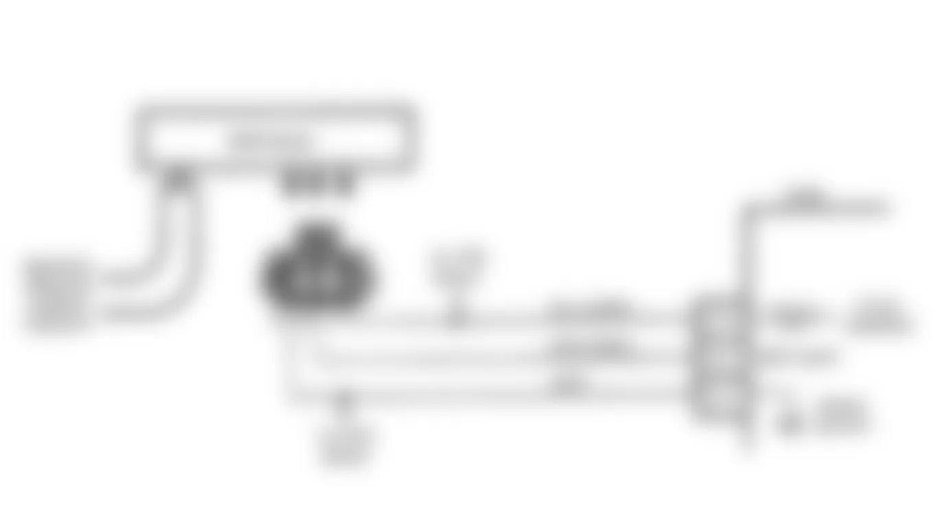
Fig. 58: Isuzu Stylus XS 1991 - Component Locations - Code 34 Flow Chart-MAP Sensor Circuit (Turbo)
Isuzu Stylus XS 1991 - CODE 41: CAM SIGNAL CIRCUIT (TURBO)
For timing of the injectors, Hall Effect switch is used. Hall Effect sends a signal to ECM when cylinder No. 1 is 25 degrees ATDC on compression stroke. This signal is used to start the correct injector sequence. Engine will continue to run if cam signal is lost while running, but will not restart if engine is stopped. If failure is in Hall Effect switch output Yellow/Blue wire to ECM terminal B9, a Code 41 will be set. Code 41 is set when engine is cranking.
NOTE: Test numbers refer to test numbers on diagnostic chart.
- Checks to see if B+ and ground are all at Hall Effect switch.
- Checks to see if Hall Effect sensor is sending out a signal to ECM.
- Checks to see if Yellow/Blue wire from Hall Effect to ECM is open or grounded. The amount of voltage depends upon the position of the vane in the dual cam sensor housing.
Isuzu Stylus XS 1991 - Diagnostic Aids
An intermittent may be caused by a poor connection, rubbing through the wire insulation, or a wire broken inside the insulation. If Hall Effect signal is not received by ECM for 3 seconds, check for poor connections or damaged harness. For intermittent inspection, see INTERMITTENTS in H - EFI TESTS W/O CODES article in the ENGINE PERFORMANCE Section.
Fig. 60: Isuzu Stylus XS 1991 - Component Locations - Code 41 Flow Chart-Cam Angle Circuit (Turbo)
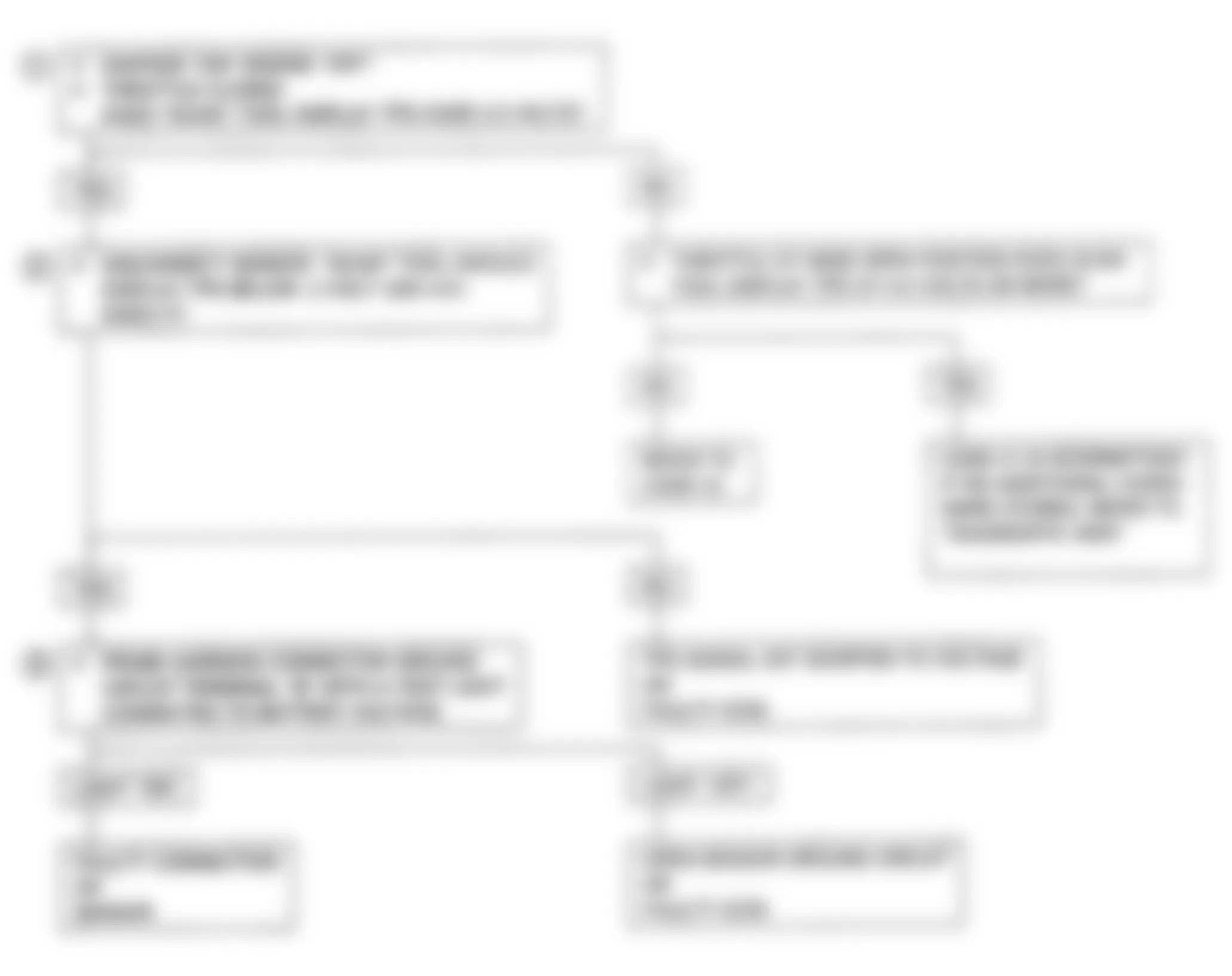
Isuzu Stylus XS 1991 - CODE 42: EST-ELECTRONIC SPARK TIMING (NON-TURBO)
Ignition module sends reference signal (circuit No. 430) to ECM when engine is cranking. When engine speed is less than 600 RPM, the ECM applies 5 volts to by-pass line (circuit No. 424) to switch the timing to be controlled by ECM.
When system is running on ignition module (no voltage on by-pass line), ignition module grounds the Electronic Spark Timing (EST) signal. The ECM expects to see no voltage on the EST line. If ECM sees a voltage signal, Code 42 will set and system will not go into EST mode.
When RPM for EST is reached (approximately 400 RPM), and by-pass voltage is applied, EST should no longer be grounded in the ignition module so EST voltage will vary. If by-pass line is open or grounded, ignition module will not switch to EST, so EST voltage will be low and Code 42 will be set.
If EST line is grounded, the ignition module will switch to EST, but because line is grounded there will be no EST signal and a Code 42 will be set.
NOTE: Test numbers refer to test numbers on diagnostic chart.
- Code 42 indicates ECM has detected an open or short to ground in EST or by-pass circuit. This confirms that Code 42 and the fault causing the code are present.
- This checks for normal EST ground path through ignition module. An EST circuit No. 423 shorted to ground will also read less than 500 ohms.
- As test light voltage touches circuit No. 424, the module should switch, causing ohmmeter to overrange if ohmmeter is adjusted to the 1000-2000 ohms range. Selecting the 10,000-20,000 ohms range will indicate greater than 5000 ohms. The important thing is that module is switched.
- If module did not switch, this checks for shorted EST circuit No. 423, open in circuit No. 424, faulty ignition module connection or faulty ignition module.
- This step confirms that Code 42 is caused by a faulty ECM and not an intermittent in circuits No. 423 and 424.

Fig. 62: Isuzu Stylus XS 1991 - Component Locations - Code 42 Flow Chart-EST Circuit (Non-Turbo)
Isuzu Stylus XS 1991 - CODE 43: ESC-ELECTRONIC SPARK CONTROL (TURBO)
ECM applies and monitors a 5-volt DC signal to the knock sensor. Internal knock sensor circuitry pulls this DC signal down to about 2.5 volts. When knock sensor detects detonation, it generates an AC signal which rides back on the DC signal to the ECM. Knock signal intensity is dependent upon knock signal level.
NOTE: Test numbers refer to test numbers on diagnostic chart.
- Code 43 will set when vehicle reaches normal operating temperature (but not overheating) and the following conditions are present for 5 seconds:
- High engine load is indicated by MAP sensor and engine speed.
- A knock signal is indicated for more than 3 seconds.
- MAT temperature is greater than 32?F (0?C).
NOTE: If an audible knock is heard from engine, repair mechanical problem first. - If tapping on engine lift hook does not produce a knock signal, try tapping on engine closer to sensor before proceeding.
- This step determines the state of the 5-volt reference signal applied to the sensor.
- Determines if fault is in knock sensor or ESC portion of MEM-CAL.
Isuzu Stylus XS 1991 - Diagnostic Aids
Check for an open or short to ground in Blue/Pink wire. Check for proper MEM-CAL installation. Check engine for a mechanical failure or misadjusted engine base timing. A Code 43 could have been set by a possible turbo overboost condition.
Fig. 63: Isuzu Stylus XS 1991 - Component Locations - Code 43 Circuit Diagram-ESC Circuit (Turbo)

Fig. 64: Isuzu Stylus XS 1991 - Component Locations - Code 43 Flow Chart-ESC Circuit (Turbo)
Isuzu Stylus XS 1991 - CODE 44: O2 SENSOR LEAN FUEL MIXTURE (DOHC NON-TURBO)
ECM supplies a voltage of approximately .45 volt between ECM terminals D6 and D7 (if measurement is taken with a 10-megohm DVOM, reading may be as low as .32 volt). The O2 sensor varies voltage from approximately .1 volt (lean exhaust) to 1.0 volt (rich exhaust). When sensor temperature is less than 600?F (316?C), the sensor acts like an open circuit and will not produce voltage. An open sensor circuit or cold sensor will cause an open loop condition.
NOTE: Test numbers refer to test numbers on diagnostic chart.
- Code 44 will set under following conditions:
- Coolant temperature is greater than 158?F (70?C).
- Engine running for more than 50 seconds.
- Integrator count is not at 128.
- No Code 21A, 21B, 33A, or 33B is set.
- Oxygen sensor voltage is below .278 mV for 99 seconds.
- System is in closed loop.
- TPS is greater than 3 percent.
Isuzu Stylus XS 1991 - Diagnostic Aids
Using Scan tester, observe block learn value at different RPM. Scan tester also displays block cells, so block learn values can be checked in each of the cells, to determine when Code 44 set. If conditions for Code 44 exist, block learn values will be approximately 150.
Scan Tester:
- Ensure oxygen sensor pigtail is not contacting exhaust manifold.
- Check for ground in wire between connector and oxygen sensor.
- Water delivered to fuel injectors can cause a lean mixture. This can set a Code 44.
- Fuel system will be lean if pressure is too low. Monitor fuel pressure while driving at various road speeds and/or loads to confirm a problem (if necessary).
- If exhaust leak is present, outside air can be pulled into the exhaust and past the sensor. Vacuum or crankcase leaks can also cause a lean condition.
- If heater portion of oxygen sensor fails, this may set a Code 44 or 45. See appropriate I - EFI SYS/COMP TESTS article in the ENGINE PERFORMANCE Section.
For intermittent inspection, see INTERMITTENTS in H - EFI TESTS W/O CODES article in the ENGINE PERFORMANCE Section.


Isuzu Stylus XS 1991 - CODE 44: O2 SENSOR LEAN FUEL MIXTURE (TURBO)
The ECM supplies a voltage of approximately .43 volt between ECM terminals D6 and D7 (if measurement is taken with a 10-megohm DVOM, reading may be as low as .32 volt). The O2 sensor varies voltage from approximately .1 volt (lean exhaust) to 1.0 volt (rich exhaust). When sensor temperature is less than 600?F (316?C), the sensor acts like an open circuit and will not produce voltage. An open sensor circuit or cold sensor will cause an open loop condition.
NOTE: Test numbers refer to test numbers on diagnostic chart.
- Code 44 will set under following conditions:
- Coolant temperature is greater than 158?F (70?C).
- Engine running for more than 50 seconds.
- Integrator count is not at 128.
- No Code 21 or 33 is set.
- Oxygen sensor voltage is fixed below .05 volt.
- System is in closed loop.
- TPS is greater than 3.5 percent and less than 13.3 percent at less than 3000 RPM.
Isuzu Stylus XS 1991 - Diagnostic Aids
Using Scan tester, observe block learn value at different RPM. Scan tester also displays block cells, so block learn values can be checked in each of the cells, to determine when Code 44 set. If conditions for Code 44 exist, block learn values will be approximately 150.
Scan Tester:
- Ensure oxygen sensor pigtail is not contacting exhaust manifold.
- Check for ground in wire between connector and oxygen sensor.
- Water delivered to fuel injectors can cause a lean mixture. This can set a Code 44.
- Fuel system will be lean if pressure is too low. Monitor fuel pressure while driving at various road speeds and/or loads to confirm a problem (if necessary).
- If exhaust leak is present, outside air can be pulled into the exhaust and past the sensor. Vacuum or crankcase leaks can also cause a lean condition.
- If heater portion of oxygen sensor fails, this may set a Code 44 or 45. See appropriate I - EFI SYS/COMP TESTS article in the ENGINE PERFORMANCE Section
For intermittent inspection, see INTERMITTENTS in H - EFI TESTS W/O CODES article in the ENGINE PERFORMANCE Section.
Fig. 67: Isuzu Stylus XS 1991 - Component Locations - Code 44 Circuit Diagram-O2 Sensor Ckt. (Turbo)
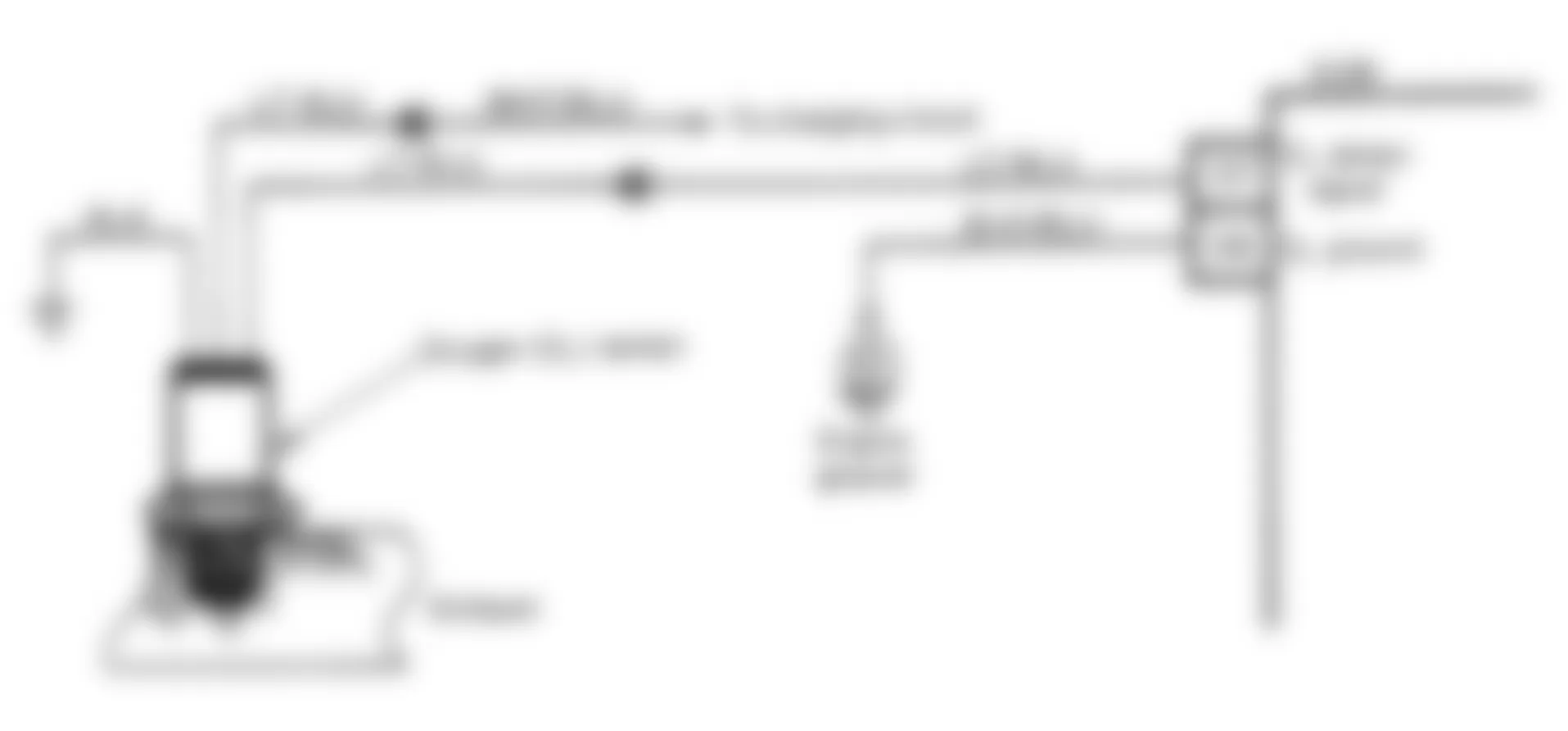
Fig. 68: Isuzu Stylus XS 1991 - Component Locations - Code 44 Flow Chart-O2 Sensor Ckt. (Turbo)

Isuzu Stylus XS 1991 - CODE 44: O2 SENSOR-LEAN FUEL MIXTURE (SOHC)
The ECM supplies a voltage of approximately .45 volt between ECM terminals D6 and D7 (if measurement is taken with a 10-megohm DVOM, reading may be as low as .32 volt). The O2 sensor varies voltage from approximately .1 volt (lean exhaust) to 1.0 volt (rich exhaust). When sensor temperature is less than 600?F (316?C), the sensor acts like an open circuit and will not produce voltage. An open sensor circuit or cold sensor will cause an open loop condition.
NOTE: Test numbers refer to test numbers on diagnostic chart.
- Code 44 will set under following conditions:
- Coolant temperature is greater than 158?F (70?C).
- Engine running for more than 50 seconds.
- Integrator count is not at 128.
- No Code 21A, 21B, 33A, or 33B is set.
- Oxygen sensor voltage is below .278 mV for 99 seconds.
- System is in closed loop.
- TPS is greater than 3 percent.
Isuzu Stylus XS 1991 - Diagnostic Aids
Using Scan tester, observe block learn values at different RPMs. Scan tester also displays block cells, so block learn values can be checked in each of the cells, to determine when Code 44 set. If conditions for Code 44 exist, block learn values will be approximately 150.
Scan Tester:
- Ensure oxygen sensor pigtail is not contacting exhaust manifold.
- Check for ground in wire between connector and oxygen sensor.
- Water delivered to fuel injectors can cause a lean mixture. This can set a Code 44.
- Fuel system will be lean if pressure is too low. Monitor fuel pressure while driving at various road speeds and/or loads to confirm a problem (if necessary).
- If exhaust leak is present, outside air can be pulled into the exhaust and past the sensor. Vacuum or crankcase leaks can also cause a lean condition.
For intermittent inspection, see INTERMITTENTS in H - EFI TESTS W/O CODES article in the ENGINE PERFORMANCE Section.
Fig. 69: Isuzu Stylus XS 1991 - Component Locations - Code 44 Circuit Diagram-O2 Sensor Ckt. (SOHC)
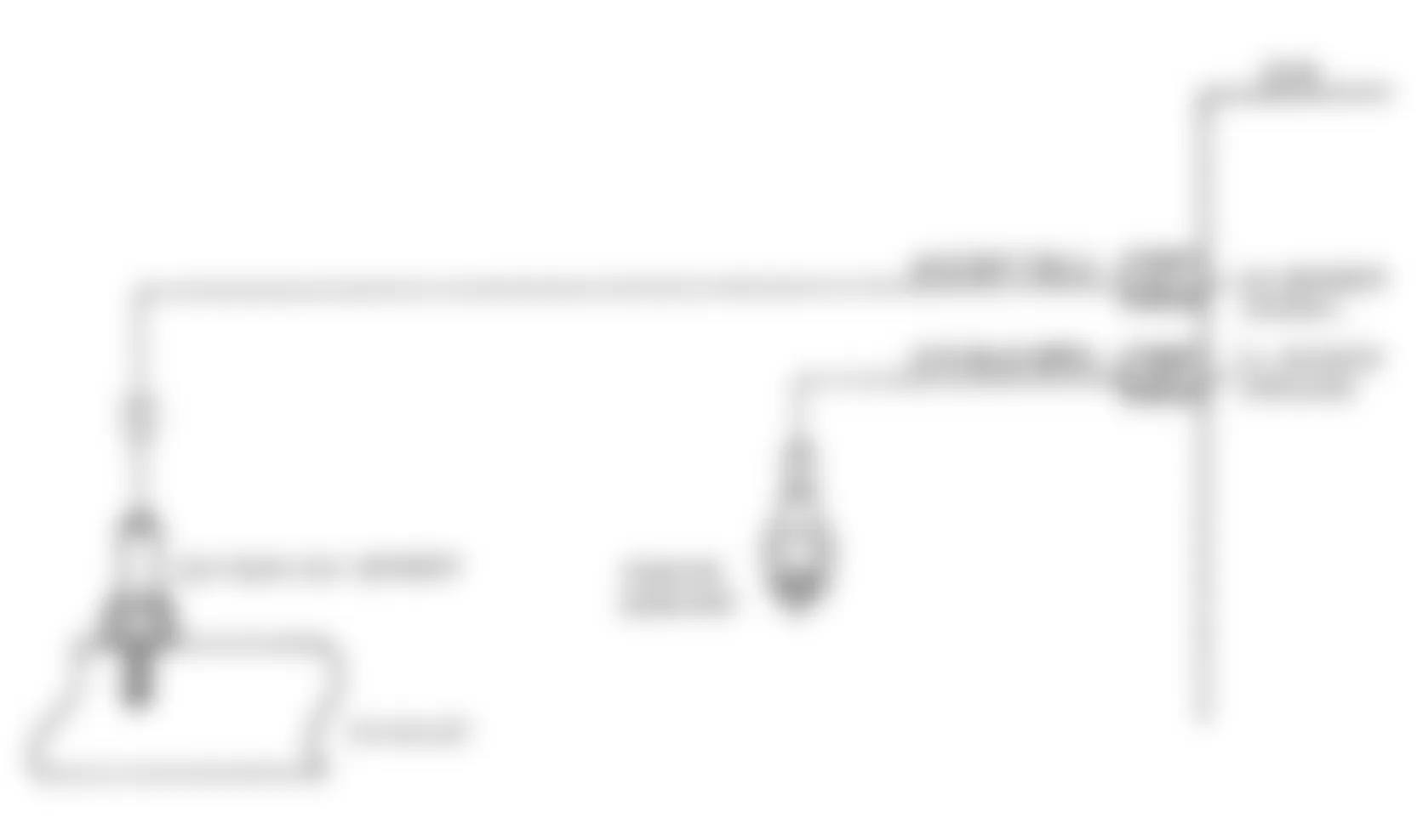
Fig. 70: Isuzu Stylus XS 1991 - Component Locations - Code 44 Flow Chart-O2 Sensor Ckt. (SOHC)

Isuzu Stylus XS 1991 - CODE 45: O2 SENSOR RICH FUEL MIXTURE (DOHC NON-TURBO)
The ECM supplies a voltage of approximately .45 volt between ECM terminals D6 and D7 (if measurement is taken with a 10-megohm DVOM, reading may be as low as .32 volt). The O2 sensor varies voltage from approximately .1 volt (lean exhaust) to 1.0 volt (rich exhaust). When sensor temperature is less than 600?F (316?C), the sensor acts like an open circuit and will not produce voltage. An open sensor circuit or cold sensor will cause an open loop condition.
NOTE: Test numbers refer to test numbers on diagnostic chart.
- Code 45 will set when sensor voltage signal is greater than .75 volt under following conditions:
- Coolant temperature is greater than 158?F (70?C).
- Integrator count is not at 128.
- No Code 21A, 21B 33A or 33B is set.
- TPS is greater than 3 percent.
- System is in closed loop.
Isuzu Stylus XS 1991 - Diagnostic Aids
Code 45 is most likely caused by one of the following:
- Fuel system will go rich if pressure is too high. The ECM can compensate for some increase. If pressure is excessive, a Code 45 may be set.
- If an open occurs in circuit No. 450, HEI-induced electrical noise may result, causing simulated reference pulses to be picked up by ECM. Additional pulses result in a higher than actual engine speed signal. The ECM will increase pulse width to match fuel requirements of increased RPM signal. Tachometer will show higher than actual RPM, which can help in diagnosing this problem.
- Check charcoal canister for fuel saturation. If full of fuel, check canister control and hoses.
- A MAP sensor output causing ECM to sense lower than normal vacuum can cause system to go rich. Disconnecting MAP sensor allows ECM to set a fixed value for the sensor. Substitute a different MAP sensor if rich condition is gone when sensor is disconnected.
- An intermittent TPS output causes system to go rich due to a false engine acceleration indication.
- A contaminated oxygen sensor can cause a false signal. The ECM will reduce fuel delivery causing a driveability problem. Inspect oxygen sensor for silicone contamination from fuel or improper use of RTV sealant.
- A sticking EGR valve creates a rich condition, accompanied by rough idle. Check EGR valve operation.
For intermittent inspection, see INTERMITTENTS in H - EFI TESTS W/O CODES article in the ENGINE PERFORMANCE Section.


Isuzu Stylus XS 1991 - CODE 45: O2 SENSOR RICH FUEL MIXTURE (TURBO)
The ECM supplies a voltage of approximately .45 volt between ECM terminals D6 and D7 (if measurement is taken with a 10-megohm DVOM, reading may be as low as .32 volt). The O2 sensor varies voltage from approximately .1 volt (lean exhaust) to approximately 1.0 volt (rich exhaust). When sensor temperature is less than 600?F (316?C), the sensor acts like an open circuit and will not produce voltage. An open sensor circuit or cold sensor will cause an open loop condition.
NOTE: Test numbers refer to test numbers on diagnostic chart.
- Code 45 will set when sensor voltage signal is greater than .85 volt under following conditions:
- Coolant temperature is greater than 158?F (70?C).
- Integrator count is not at 128.
- No Code 21 or 33 is set.
- TPS is greater than 3.5 percent and less than 13.3 percent.
- System is in closed loop.
Isuzu Stylus XS 1991 - Diagnostic Aids
Code 45 is most likely caused by one of the following:
- Fuel system will go rich if pressure is too high. The ECM can compensate for some increase. If pressure is excessive, a Code 45 may be set.
- If an open occurs in Yellow/Black wire from ignition coil, HEI-induced electrical noise may result, causing simulated reference pulses to be picked up by ECM. Additional pulses result in a higher than actual engine speed signal. The ECM will increase pulse width to match fuel requirements of increased RPM signal. Tachometer will show higher than actual RPM, which can help in diagnosing this problem.
- Check charcoal canister for fuel saturation. If full of fuel, check canister control and hoses.
- A MAP sensor output causing ECM to sense lower than normal vacuum can cause system to go rich. Disconnecting MAP sensor allows ECM to set a fixed value for the sensor. Substitute a different MAP sensor if rich condition is gone when sensor is disconnected.
- An intermittent TPS output causes system to go rich due to a false engine acceleration indication.
- A contaminated oxygen sensor can cause a false signal. The ECM will reduce fuel delivery causing a driveability problem. Inspect oxygen sensor for silicone contamination from fuel or improper use of RTV sealant.
- A sticking EGR valve creates a rich condition, accompanied by rough idle. Check EGR valve operation.
For intermittent inspection, see INTERMITTENTS in H - EFI TESTS W/O CODES article in the ENGINE PERFORMANCE Section
Fig. 73: Isuzu Stylus XS 1991 - Component Locations - Code 45 Circuit Diagram-O2 Sensor Ckt. (Turbo)

Fig. 74: Isuzu Stylus XS 1991 - Component Locations - Code 45 Flow Chart-O2 Sensor Ckt. (Turbo)

Isuzu Stylus XS 1991 - CODE 45: O2 SENSOR RICH FUEL MIXTURE (SOHC)
The ECM supplies a voltage of approximately .43 volt between ECM terminals D6 and D7 (if measurement is taken with a 10-megohm DVOM, reading may be as low as .32 volt). The O2 sensor varies voltage from .1 volt (lean exhaust) to 1 volt (rich exhaust). When sensor temperature is less than 600?F (316?C), the sensor acts like an open circuit and will not produce voltage. An open sensor circuit or cold sensor will cause an open loop condition.
NOTE: Test numbers refer to test numbers on diagnostic chart.
- Code 45 will set when sensor voltage signal is greater than .75 volt under following conditions:
- Coolant temperature is greater than 158?F (70?C).
- Integrator count is not at 128.
- No Code 21A, 21B 33A or 33B is set.
- TPS is greater than 3 percent.
- System is in closed loop.
Isuzu Stylus XS 1991 - Diagnostic Aids
Code 45 is most likely caused by one of the following:
- Fuel system will go rich if pressure is too high. The ECM can compensate for some increase. If pressure is excessive, a Code 45 may be set.
- If an open occurs in circuit No. 453, HEI-induced electrical noise may result, causing simulated reference pulses to be picked up by ECM. Additional pulses result in a higher than actual engine speed signal. The ECM will increase pulse width to match fuel requirements of increased RPM signal. Tachometer will show higher than actual RPM, which can help in diagnosing this problem.
- Check charcoal canister for fuel saturation. If full of fuel, check canister control and hoses.
- A MAP sensor output causing ECM to sense lower than normal vacuum can cause system to go rich. Disconnecting MAP sensor allows ECM to set a fixed value for the sensor. Substitute a different MAP sensor if rich condition is gone when sensor is disconnected.
- An intermittent TPS output causes system to go rich due to a false engine acceleration indication.
- A contaminated oxygen sensor can cause a false signal. The ECM will reduce fuel delivery causing a driveability problem. Inspect oxygen sensor for silicone contamination from fuel or improper use of RTV sealant.
- A sticking EGR valve creates a rich condition, accompanied by rough idle. Check EGR valve operation.
For intermittent inspection, see INTERMITTENTS in H - EFI TESTS W/O CODES article in the ENGINE PERFORMANCE Section.
Fig. 75: Isuzu Stylus XS 1991 - Component Locations - Code 45 Circuit Diagram-O2 Sensor Ckt. (SOHC)

Fig. 76: Isuzu Stylus XS 1991 - Component Locations - Code 45 Flow Chart-O2 Sensor Ckt. (SOHC)

Isuzu Stylus XS 1991 - CODE 51: ECM FAILURE (MEM-CAL ERROR ON TURBO)
Check all ECM connections. If connections are okay, clear memory and recheck system. See CLEARING TROUBLE CODES in this article. If Code 51 reappears, replace ECM. Clear codes and confirm closed loop operation. Ensure CHECK ENGINE light is off.
Isuzu Stylus XS 1991 - SUMMARY
If no hard fault codes (or only pass codes) are present, driveability symptoms exist or intermittent codes exist, proceed to H - EFI TESTS W/O CODES article in the ENGINE PERFORMANCE Section for diagnosis by symptom (i.e., ROUGH IDLE, NO START, etc.) or intermittent diagnosis procedures.