
Isuzu Trooper LS 1994 - 1994 ENGINE PERFORMANCE Self-Diagnostics - Trooper - Fuel Injection - 3.2L
Isuzu Trooper LS 1994 - INTRODUCTION
NOTE: Assembly Line Data Link (ALDL) connector may also be referred to as Data Link Connector (DLC). The term CHECK ENGINE light is now referred to as Malfunction Indicator Light (MIL). The MIL is displayed in instrument cluster as CHECK ENGINE. Electronic Control Module (ECM) may also be referred to as Powertrain Control Module (PCM).
If no faults were found while performing BASIC DIAGNOSTIC PROCEDURES, proceed with self-diagnostics. If no fault codes or only pass codes are present after entering self-diagnostics, proceed to appropriate H - 3.2L EFI TEST W/O CODES article or diagnosis by symptom (i.e., ROUGH IDLE, NO START, etc.).
Isuzu Trooper LS 1994 - SELF-DIAGNOSTIC SYSTEM HARD FAILURES
Hard failures cause MIL to illuminate and remain on until problem is repaired. If light comes on and remains on (light may flash) during vehicle operation, cause of malfunction must be determined using diagnostic (code) charts. See CODE CHARTS. If a sensor fails, Electronic Control Module (ECM) will use a substitute value in its calculations to continue engine operation. In this condition, commonly known as limp-in mode, the vehicle runs but driveability will not be optimum.
Isuzu Trooper LS 1994 - INTERMITTENT FAILURES
Intermittent failures may cause MIL to flicker or illuminate and go out after intermittent fault goes away. However, the corresponding trouble code will be retained in Electronic Control Module (ECM) memory. If related fault does not reoccur within a certain time frame, related trouble code will be erased from ECM memory. Intermittent failures may be caused by a sensor, connector or wiring related problems. See INTERMITTENTS in H - 3.2L EFI TEST W/O CODES article.
Isuzu Trooper LS 1994 - RETRIEVING CODES
NOTE: Codes can also be retrieved using a scan tester. Trouble codes may also be referred to as DTC.
- The MIL will come on when ignition is on and engine is not running. When engine is started, MIL should go off. If light remains on while engine is running, a trouble code is present.
- If light does not come on with ignition on and engine off, check MIL circuit before continuing. See DIAGNOSTIC CIRCUIT CHECK under CODE CHARTS if MIL fails to operate.
- To retrieve codes, install a jumper wire between DLC terminals "1" and "3". DLC is located behind center console, to right of accelerator pedal. See Fig. 1 .

Fig. 1: Isuzu Trooper LS 1994 - Component Locations - Identifying DLC (ALDL) Connector Location - Turn ignition on and count number of flashes from MIL to identify codes. See Fig. 2 . Each code will be flashed 3 times starting with lowest code number.
- If system is operating properly (with no trouble codes present), Code 12 should be displayed with ignition on and engine off. This indicates diagnostic system is capable of storing codes and providing diagnostic information.
- Once all codes are displayed, cycle will repeat. Remove jumper wire from DLC after codes have been retrieved.
Fig. 2: Isuzu Trooper LS 1994 - Component Locations - Code Display (Typical)

Isuzu Trooper LS 1994 - CLEARING CODES
CAUTION: Ensure ignition is off when disconnecting or reconnecting power supply to ECM.
- After repairs are performed, clear ECM memory of all stored trouble codes. To clear memory, turn ignition off. Remove ECM MAIN relay (located in relay center, near battery) for at least 30 seconds.
- After clearing trouble codes, confirm system will operate in closed loop mode and ensure MIL functions properly. Trouble codes can also be cleared by disconnecting vehicle battery. However, other memory functions (clock, radio, etc.) will require resetting.
Isuzu Trooper LS 1994 - CODE CHARTS TROUBLE CODE DEFINITION
Isuzu Trooper LS 1994 TROUBLE CODE IDENTIFICATION
Code System Affected Probable Cause 12 System Normal System Normal 13 O2 Sensor Sensor or Circuit ECM 14A (1) Coolant Temperature Sensor Sensor or Circuit, ECM 14B (2) Coolant Temperature Sensor Sensor or Circuit, ECM 21A TPS Signal (High) TPS, ECM 21B TPS Signal (Low) TPS, ECM 23A MAT Circuit (Low) Sensor or Circuit, ECM 23B MAT Circuit (High) Sensor or Circuit, ECM 24 Vehicle Speed Sensor Sensor or Circuit, ECM 32 EGR System EGR Valve, Wiring Circuit EGR Solenoid, EGR Filter, EVRV, ECM 33A MAP Sensor Signal (High) Sensor or Circuit, ECM 33B MAP Sensor Signal (Low) Sensor or Circuit, ECM 42 Electronic Spark Timing Wiring Circuit, Ignition Module, ECM 43 Electronic Spark Control Knock Sensor or Circuit, ESC Module or ECM 44 O2 Sensor (Lean) Injectors, Fuel Pressure,Exhaust Leaks, O2 Sensor or Circuit, MAP Sensor or ECM 45 O2 Sensor (Rich) Injectors, Fuel Pressure,O2 Sensor or Circuit, MAP Sensor, TPS, Canister Purge Ignition Shielding, ECM 51 PROM Error PROM or ECM
(1) High temperature indicated by temperature sensor.
(2) Low temperature indicated by temperature sensor.
Isuzu Trooper LS 1994 - DIAGNOSTIC CIRCUIT CHECK
Isuzu Trooper LS 1994 SCAN DATA
Scan Position (1) Data Value A/C No (Yes W/ A/C Requested) A/C Clutch Off (On W/ A/C Requested) Air Control Solenoid Off Air Fuel Ratio 0-25.5:1 Battery 13-15 Volts BARO- Voltage Varies Depending On Altitude BLE (Block Learn Enable) Yes BLM (Block Learn Memory) 116-145 Counts Block Learn Cell 1 BPW (Base Pulse Width) 0-499.9 Milliseconds Canister Purge Off Coolant Temperature 185-221?F (85-105?C) EGR Solenoid Off EST (Electronic Spark Timing) Yes IAC (Idle Air Control) 1-50 Counts Idle Throttle Yes INT (Integrator) Varied 108-154 Counts Knock Retard 0-45 Degrees MAP (Manifold Absolute Pressure) (2) 1-2 Volts MAT (Manifold Air Temperature) (3) 50-199?F (10-93?C) Open/Closed Loop Closed Loop Oxygen Sensor (3) .1-1.0 Volt PARK/NEUTRAL Position Park/Neutral Power Steering Switch Normal Prom Identification 0-65535 RPM (4) (5) RPM Is Controlled By ECM Rich/Lean Flag Varies Second Throttle Solenoid Off (On Above 5000 RPM) Shift Light Off Spark Advance Varies Throttle Angle Zero Percent At Idle TPS (Throttle Position Sensor) .50-.1.25 Volts VSS (Vehicle Speed Sensor) 0 MPH
(1) With engine idling at normal operating temperature, in Park or Neutral, system in closed loop and all accessories off.
(2) Voltage varies with vacuum and barometric pressure.
(3) Voltage varies with exhaust temperature.
(4) Plus or minus 50 RPM from desired RPM (A/T).
(5) Plus or minus 100 RPM from desired RPM (M/T).
Diagnostic circuit check will identify problem created by Electronic Engine Control System (EECS) malfunction. It is the starting point for diagnosis. This check will direct you to the next logical step in diagnosing the complaint.
After completing diagnostic circuit check and finding on-board diagnostics functioning properly with no trouble codes displayed, use appropriate SCAN DATA table for comparison.
Data values must be taken under these conditions:
- Engine at normal operating temperature.
- Engine running at idle.
- Vehicle in Park or Neutral.
- System in closed loop.
The values are an average of displayed values recorded from normal operating vehicles. Values represent what a normal functioning system would typically display.
NOTE: Only parameters supplied by manufacturer are used in this article. If a scan tester reads other parameters, values are not recommended by manufacturer for diagnostic use. A scan tester displaying faulty data should not be used, or misdiagnosis will occur. Report problem to scan tester manufacturer.
NOTE: Test numbers refer to numbers on diagnostic chart.
- This step checks if ECM can provide a ground path for CHECK ENGINE light. This is a bulb check.
- This step checks if ECM can perform internal diagnostics.
- This step checks if ECM can supply serial data for scan tester.
- This step verifies scan data.
- This step checks whether ECM or electrical system is cause of no start.
- This step checks ECM memory for codes to aid in diagnosis.
Fig. 3: Isuzu Trooper LS 1994 - Component Locations - Diagnostic Circuit Check
Isuzu Trooper LS 1994 - ECM LOCATION
On Trooper, ECM is located behind center console to right of accelerator pedal.
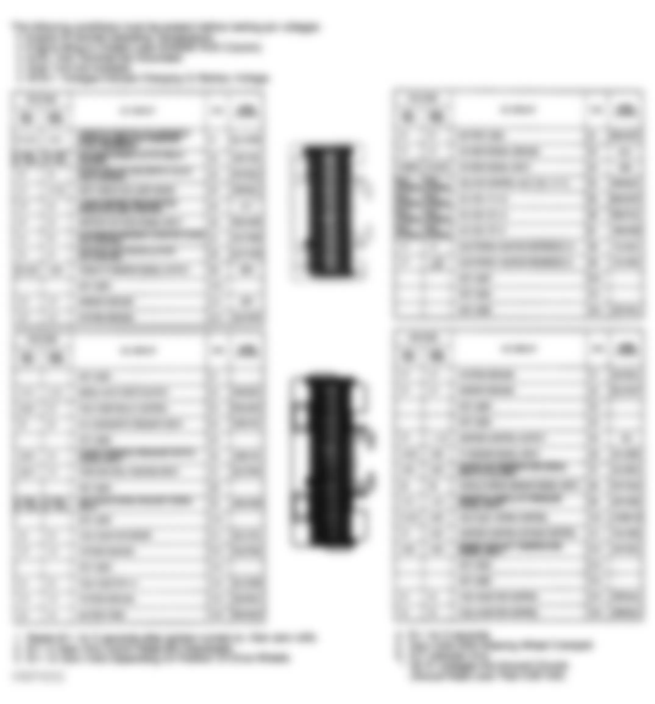
Isuzu Trooper LS 1994 - ECM TERMINAL IDENTIFICATION (TROOPER)
The following conditions must be present before testing pin voltages:
- Engine at normal operating temperature.
- Engine idling in closed loop (ENGINE RUN column).
- ALDL test terminal not grounded.
- All B+ voltages indicate charging or battery voltage.
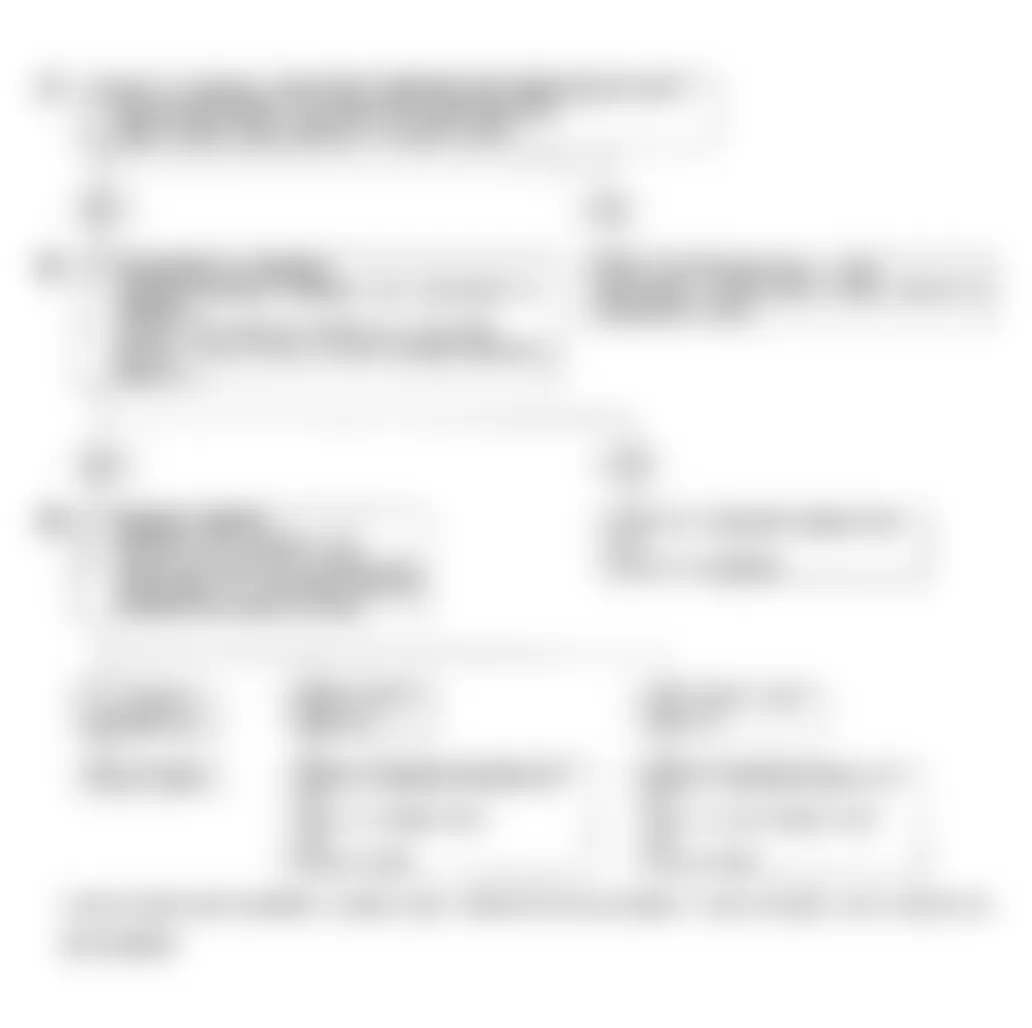
Isuzu Trooper LS 1994 - CHART A-1 - NO CHECK ENGINE LIGHT
There should always be a steady CHECK ENGINE light when ignition is on and engine off. Electronic Control Module (ECM) will also turn on light if ECM senses a malfunction or ECM fails.
NOTE: Test numbers refer to numbers on diagnostic chart.
- Test light provides a ground source to CHECK ENGINE light. If circuit is okay, CHECK ENGINE light should be on when circuit No. A5 is probed.
- Battery voltage at circuits No. B1 and C16 is protected by a 30-amp fusible link in relay center, near battery. If circuits No. B1 and C16 have voltage, ECM or ECM grounds are faulty.
- Using a test light connected to 12 volts, probe each system ground circuit to ensure a good ground is present.
Isuzu Trooper LS 1994 - Diagnostic Aids
Engine Runs Okay - Check for faulty light bulb, open in circuit No. A5 or defective gauge fuse. This will result in no oil indicator light, alternator light, seat belt reminder light, etc.
Engine Cranks, But Will Not Run - Check for continuous battery drain, fuse or fusible link open, ECM ignition fuse open, battery circuits No. B1 and C16 to ECM open, ignition circuit No. A6 to ECM open or poor connection to ECM.
Fig. 5: Isuzu Trooper LS 1994 - Component Locations - Chart A-1 - Schematic

Fig. 6: Isuzu Trooper LS 1994 - Component Locations - Chart A-1 - Diagnostic Flowchart

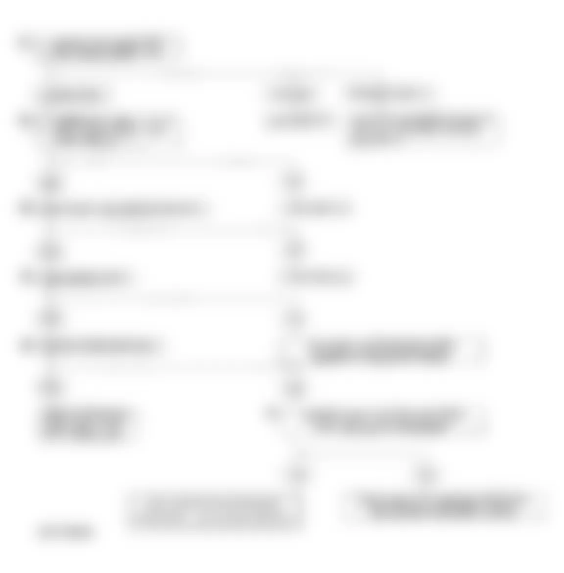
Isuzu Trooper LS 1994 - CHART A-2 - NO ALDL DATA OR WILL NOT FLASH CODE 12 (CHECK ENGINE LIGHT ON STEADY)
There should always be a steady CHECK ENGINE light when ignition is on and engine off. With diagnostic terminal grounded, light should flash a Code 12, followed by any trouble codes stored in memory. A steady light could be a short to ground in circuit from ECM terminal No. A5 or an open in diagnostic circuit No. C4.
NOTE: Test numbers refer to numbers on diagnostic chart.
- If there is problem with ECM not allowing scan tester to read serial data, ECM should not flash Code 12. If Code 12 is flashed, ensure scan tester is working properly by testing it on another vehicle. If scan tester is functioning properly and circuit No. C2 (serial data) is okay, the ECM may be at fault.
- If light goes off when ECM connector is disconnected, then circuit No. A5 is not shorted to ground.
- This checks for an open diagnostic circuit No. C4 (diagnostic request input).
- At this point, CHECK ENGINE light wiring is okay. The problem is a faulty ECM. If Code 12 is not flashed, replace ECM.
Fig. 7: Isuzu Trooper LS 1994 - Component Locations - Chart A-2 - Schematic
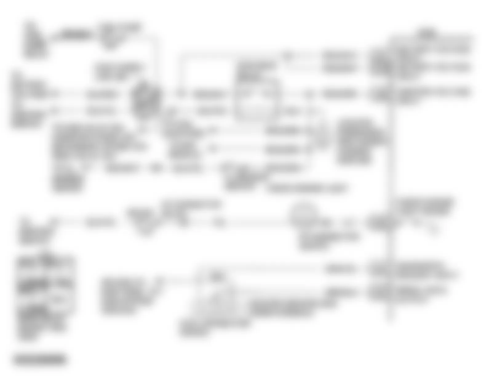
Fig. 8: Isuzu Trooper LS 1994 - Component Locations - Chart A-2 - Diagnostic Flowchart

Isuzu Trooper LS 1994 - CODE 13 - OXYGEN (O2) SENSOR (OPEN CIRCUIT)
The ECM supplies .45 volt between terminals No. B2 and B3. When oxygen sensor reaches operating temperature, it varies this voltage from approximately one volt (rich exhaust) to approximately .10 volt (lean exhaust). A heater, incorporated in O2 sensor, is used to heat sensor, causing sensor to produce voltage signal sooner. Heater portion of sensor will not affect Code 13. Oxygen sensor produces no voltage when temperature is less than 572?F (300?C). An open sensor circuit or cold sensor causes open loop operation.
NOTE: Test numbers refer to numbers on diagnostic chart.
- Code 13 will set under following conditions: engine is at normal operating temperature, engine has been running at least 3 minutes, oxygen signal voltage is steady between .35 and .55 volts, throttle position sensor signal is greater than 10 percent, and no Code 21 or 31 is set. All conditions must be met for approximately 40 seconds. If conditions for a Code 13 exist, system will not go into closed loop.
- This determines if sensor, wiring or ECM is the cause of Code 13.
- Use only a high impedance (10-megohm) digital volt-ohmmeter. This checks continuity of circuits No. B2 and B3. If circuit No. B2 is open, ECM voltage on circuit No. B3 will be greater than .6 volt.
Isuzu Trooper LS 1994 - Diagnostic Aids
Normal scan tester voltage varies between .1-1.0 volt while in closed loop. Code 13 sets in approximately 40 seconds if voltage remains between .35 and .55 volt, but system will enter open loop in approximately 15 seconds. For intermittent inspection, see appropriate H - 3.2L EFI TEST W/O CODES article.
Fig. 9: Isuzu Trooper LS 1994 - Component Locations - Code 13 - Schematic

Fig. 10: Isuzu Trooper LS 1994 - Component Locations - Code 13 - Diagnostic Flowchart (1 Of 2)

Fig. 11: Isuzu Trooper LS 1994 - Component Locations - Code 13 - Diagnostic Flowchart (2 Of 2)
Isuzu Trooper LS 1994 - CODE 14A - CTS CIRCUIT (HIGH TEMPERATURE INDICATED)
Coolant temperature sensor controls signal voltage to the ECM. The ECM applies voltage on circuit No. D12 to the sensor. When engine is cold, sensor resistance is high and ECM will see a high signal voltage. As engine warms, sensor resistance decreases and ECM will see a low signal voltage. When engine reaches normal operating temperature, signal voltage will be approximately 1.5-2.0 volts at the ECM. Coolant temperature is one of the inputs used to control fuel delivery, Electronic Spark Timing (EST) and Idle Air Control (IAC).
NOTE: Test numbers refer to numbers on diagnostic chart.
- Code 14A will set if engine has been running for at least 3 minutes and signal voltage indicates a coolant temperature greater than 302?F (150?C).
- This simulates conditions for Code 14B. If ECM recognizes open circuit (high voltage) and displays low temperature, ECM and wiring are okay.
Isuzu Trooper LS 1994 - Diagnostic Aids
After engine is started, temperature should rise steadily to approximately 194?F (90?C), and then stabilize when thermostat opens. When a Code 14A is set, ECM will turn on engine cooling fan. Code 14A will set if circuit No. D12 is shorted to ground. For intermittent inspection, see H - 3.2L EFI TEST W/O CODES article.
Fig. 12: Isuzu Trooper LS 1994 - Component Locations - Code 14A - Schematic

Fig. 13: Isuzu Trooper LS 1994 - Component Locations - Code 14A - Diagnostic Flowchart

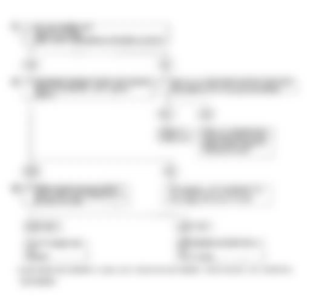
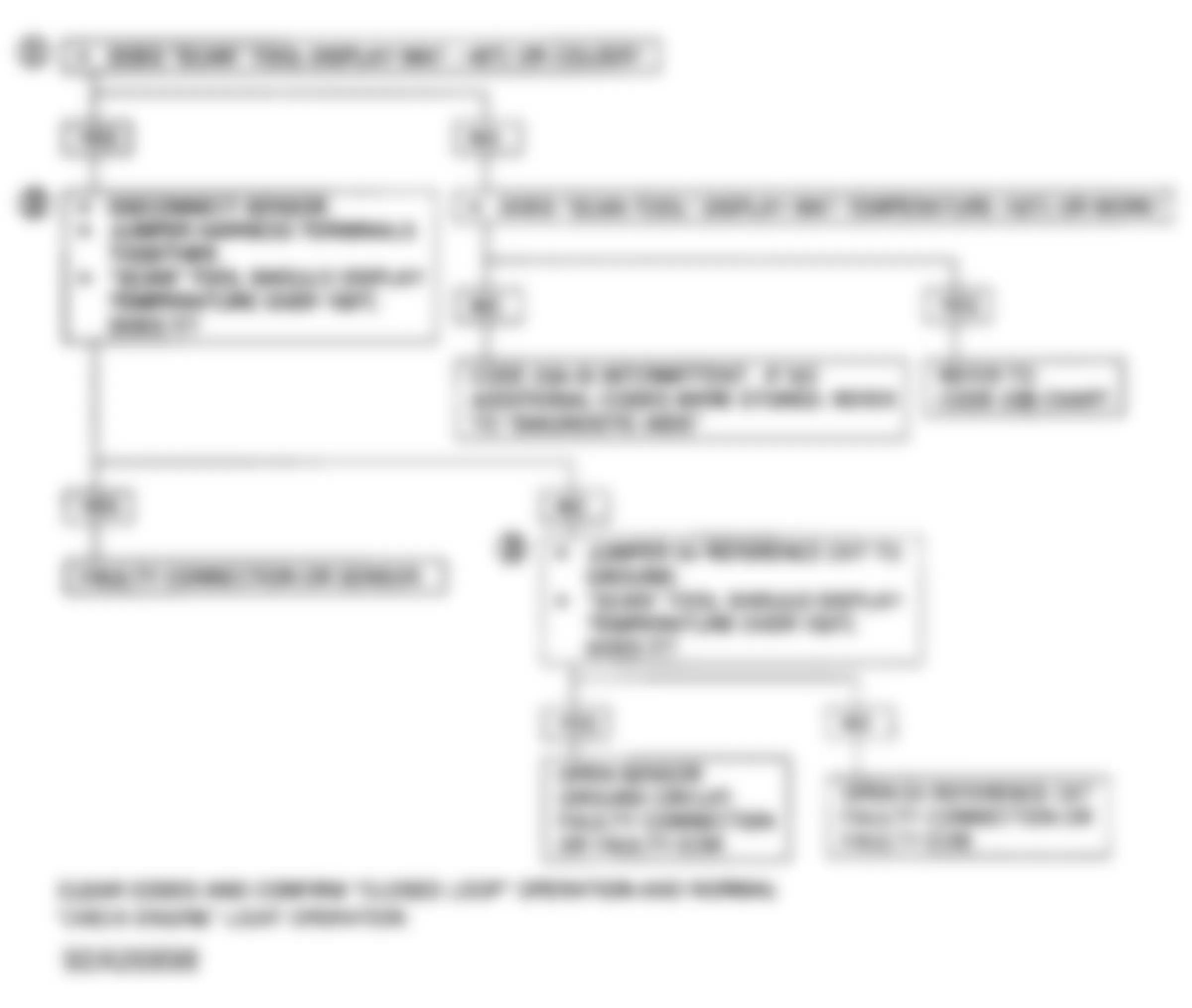
Isuzu Trooper LS 1994 - CODE 14B - CTS CIRCUIT (LOW TEMPERATURE INDICATED)
Coolant temperature sensor controls signal voltage to the ECM. The ECM applies voltage on circuit No. D12 to the sensor. When engine is cold, sensor resistance is high and ECM will see a high signal voltage. As engine warms, sensor resistance decreases and ECM will see a low signal voltage. When engine reaches normal operating temperature, signal voltage will be approximately 1.5-2.0 volts at the ECM. Coolant temperature is one of the inputs used to control fuel delivery, Electronic Spark Timing (EST) and Idle Air Control (IAC).
NOTE: Test numbers refer to numbers on diagnostic chart.
- Code 14B will set if engine has been running at least 3 minutes and coolant temperature is less than -35?F (-37?C) for 3 seconds.
- This simulates a Code 14A. If ECM recognizes low signal voltage (high temperature), ECM and wiring are okay.
- This determines if circuit No. A11 is open. Scan tester should display high temperature.
Isuzu Trooper LS 1994 - Diagnostic Aids
After engine is started, temperature should rise steadily to approximately 194?F (90?C), then stabilize when thermostat opens. Code 14B will set if circuits No. A11 and D12 are open. Check terminals at sensor for good contact. For intermittent inspection, see appropriate H - 3.2L EFI TEST W/O CODES article.
Fig. 14: Isuzu Trooper LS 1994 - Component Locations - Code 14B - Schematic

Fig. 15: Isuzu Trooper LS 1994 - Component Locations - Code 14B - Diagnostic Flowchart

Isuzu Trooper LS 1994 - CODE 21A - TPS CIRCUIT (SIGNAL VOLTAGE HIGH)
Throttle Position Sensor (TPS) provides a voltage signal which changes relative to throttle opening. Signal voltage varies from less than approximately one volt at idle to approximately 5 volts at Wide Open Throttle (WOT). The TPS signal is used by ECM for fuel control and most ECM-controlled outputs.
NOTE: Test numbers refer to numbers on diagnostic chart.
- Code 21A will set if TPS signal voltage is greater than 4.6 volts, engine speed is less than 1200 RPM, MAP is less than 7.3 psi (50 kPa), and all conditions are met for 5 seconds.
- This simulates conditions for a Code 21B. If ECM recognizes change of state, ECM and circuits No. A1 and D6 are okay.
- This isolates a faulty sensor or ECM, or an open in circuit No. D2. If circuit No. D2 is open, Code 23A may set. Using a test light connected to 12 volts, probe sensor ground circuit No. D2. This checks 5-volt return circuit. If 5-volt return circuit is faulty, Code 21A will set.
Isuzu Trooper LS 1994 - Diagnostic Aids
The scan tester reads throttle position in volts. With ignition on, reading should be less than 1.25 volts with throttle closed. Voltage should increase at a steady rate as throttle is moved toward WOT. An open in circuit No. D2 or a short to voltage in circuit No. D6 will result in Code 21A. For intermittent inspection, see appropriate H - 3.2L EFI TEST W/O CODES article.
Fig. 16: Isuzu Trooper LS 1994 - Component Locations - Code 21A - Schematic

Fig. 17: Isuzu Trooper LS 1994 - Component Locations - Code 21A - Diagnostic Flowchart
Isuzu Trooper LS 1994 - CODE 21B - TPS CIRCUIT (SIGNAL VOLTAGE LOW)
Throttle Position Sensor (TPS) provides a voltage signal which changes relative to throttle opening. Signal voltage varies from less than approximately one volt at idle to approximately 5 volts at Wide Open Throttle (WOT). The TPS signal is used by ECM for fuel control and most ECM-controlled outputs.
NOTE: Test numbers refer to numbers on diagnostic chart.
- Code 21B will set if engine is running and TPS signal voltage is less than .2 volt.
- This simulates conditions for Code 21A. If Code 21A is set, or scan tester reads over 4 volts, ECM wiring is okay.
- Scan tester may not display 12 volts. What is important is that ECM recognizes voltage is greater than 4 volts, indicating circuit No. D6 and ECM are okay.
- If circuit No. A1 is open or shorted to ground, Code 33B may set.
Isuzu Trooper LS 1994 - Diagnostic Aids
A scan tester reads throttle position in volts. With ignition on, reading should be less than one volt with throttle closed. Voltage should increase at a steady rate as throttle is moved toward WOT. An open or short to ground in circuits No. A1 or D6 will cause Code 21B to set. For intermittent inspection, see H - 3.2L EFI TEST W/O CODES article.
Fig. 18: Isuzu Trooper LS 1994 - Component Locations - Code 21B - Schematic

Fig. 19: Isuzu Trooper LS 1994 - Component Locations - Code 21B - Diagnostic Flowchart

Isuzu Trooper LS 1994 - CODE 23A - MAT CIRCUIT (LOW TEMPERATURE INDICATED)
Manifold Air Temperature (MAT) sensor uses a thermistor to control signal to ECM. ECM applies 4-6 volts to circuit No. D7 of sensor. When manifold air is cold, sensor resistance is high and ECM will see a MAT signal. As air warms, sensor resistance is low and MAT signal drops.
NOTE: Test numbers refer to numbers on diagnostic chart.
- Code 23A will set if engine has been running for longer than 3 minutes and signal voltage indicates MAT less than -40?F (-40?C).
- This simulates conditions for Code 23B. If scan tester reads high temperature, ECM and wiring are okay.
- This checks continuity of circuits No. D2 and D7. If circuit No. D2 is open, Code 21A may also set.
Isuzu Trooper LS 1994 - Diagnostic Aids
An open in circuit No. D2 or D7 will cause Code 23A to set. For intermittent inspection, see H - 3.2L EFI TEST W/O CODES article.
Fig. 20: Isuzu Trooper LS 1994 - Component Locations - Code 23A - Schematic

Fig. 21: Isuzu Trooper LS 1994 - Component Locations - Code 23A - Diagnostic Flowchart
Isuzu Trooper LS 1994 - CODE 23B - MAT CIRCUIT (HIGH TEMPERATURE INDICATED)
Manifold Air Temperature (MAT) sensor uses a thermistor to control signal to ECM. ECM applies 4-6 volts to circuit No. D7 of sensor. When manifold air is cold, sensor resistance is high and ECM will see a MAT signal. As air warms, sensor resistance is low and MAT signal drops.
NOTE: Test number refers to number on diagnostic chart.
- Code 23B will set if engine has been running for longer than 3 minutes and a MAT greater than 302?F (150?C) is detected.
Isuzu Trooper LS 1994 - Diagnostic Aids
A Code 23B will set if circuit No. D2 or D7 becomes open or shorted to ground. For intermittent inspection, see appropriate H - 3.2L EFI TEST W/O CODES article.
Fig. 22: Isuzu Trooper LS 1994 - Component Locations - Code 23B - Schematic

Fig. 23: Isuzu Trooper LS 1994 - Component Locations - Code 23B - Diagnostic Flowchart

Isuzu Trooper LS 1994 - CODE 24 - VSS CIRCUIT
The ECM applies and monitors 12 volts on circuit No. D8. The Vehicle Speed Sensor (VSS) alternately grounds and opens circuit from ECM terminal No. D8 when vehicle is in motion. This pulsing action takes place about 4096 times per mile. ECM will calculate vehicle speed based on time between pulses. With vehicle in motion, scan tester reading should closely match speedometer reading.
NOTE: Test number refers to number on diagnostic chart.
- Code 24 will set if vehicle speed equals zero MPH when engine speed is between 1600 and 1825 RPM, MAP reading less than 3.0 psi (20.7 kPa), low speed condition (low MAP voltage, high manifold vacuum) exists, vehicle is not in Park or Neutral (A/T), all conditions are met for 1.5 seconds, and Code 33 is not set. These conditions are met during a load deceleration. Disregard Code 24 if sets when vehicle is not in motion.
Isuzu Trooper LS 1994 - Diagnostic Aids
A scan tester should indicate vehicle speed whenever vehicle is in motion. A faulty or misadjusted Park/Neutral switch can result in a false Code 24. Use scan tester to check for proper signal while vehicle is in Drive position. For intermittent inspection, see appropriate H - 3.2L EFI TEST W/O CODES article.
Fig. 24: Isuzu Trooper LS 1994 - Component Locations - Code 24 - Schematic

Fig. 25: Isuzu Trooper LS 1994 - Component Locations - Code 24 - Diagnostic Flowchart

Isuzu Trooper LS 1994 - CODE 32 - EGR SYSTEM
ECM controls EGR valve operation. ECM will ground EGR Vacuum Switching Valve (VSV) to turn EGR valve on and off. An EGR back pressure transducer determines how long EGR valve stays on, based on exhaust back pressure supplied to transducer through tube "S". EGR monitors integrator to determine if EGR system is functioning.
ECM will command EGR valve off briefly when EGR valve should be on. Integrator will change at least 3 counts, indicating EGR valve closed on command. ECM will recheck EGR system again, commanding EGR valve on when valve should be off. Integrator will change at least 3 counts, indicating EGR valve opened on command. If EGR system fails test 5 times, Code 32 will set and CHECK ENGINE light will turn on.
NOTE: Test numbers refer to numbers on diagnostic chart.
- Ensures EGR valve opens and EGR passage is not restricted.
- Ensures EGR vacuum switching valve is operating properly.
- Checks EGR back pressure transducer operation.
- Tests voltage source to EGR valve vacuum switching valve.
- Checks EGR valve for proper operation.
- Checks operation of ECM circuit to EGR vacuum switching valve.
Isuzu Trooper LS 1994 - Diagnostic Aids
A sluggish oxygen sensor can cause a false Code 32 to set. If EGR valve passage is restricted, Code 32 may set.
Fig. 26: Isuzu Trooper LS 1994 - Component Locations - Code 32 - Schematic

Fig. 27: Isuzu Trooper LS 1994 - Component Locations - Code 32 - Diagnostic Flowchart

Isuzu Trooper LS 1994 - CODE 33A - MAP SENSOR (SIGNAL VOLTAGE HIGH)
The MAP sensor responds to changes in manifold pressure (vacuum). The ECM receives a signal voltage from MAP sensor which will vary from approximately 1-1.5 volts at idle (closed throttle) to 4-4.5 volts at wide open throttle. If MAP sensor fails, ECM will substitute a fixed MAP value based on TPS to control fuel delivery.
NOTE: Test numbers refer to numbers on diagnostic chart.
- Code 33A will set when MAP signal is greater than 13.8 psi (95 kPa), TPS is less than 2 percent, and Codes 21A and 21B are not set. These conditions must be present for more than 5 seconds.
- This simulates conditions for a Code 33B. If ECM recognizes change, ECM and wiring are okay. If circuit No. A11 is open, Code 23 may also set.
Isuzu Trooper LS 1994 - Diagnostic Aids
An open in circuit No. A11 will cause Code 33A to set. If circuit No. D9 is shorted to voltage, or circuit No. D9 is shorted to circuit No. A1, Code 33A will set. With ignition on and engine off, manifold pressure is equal to atmospheric pressure and voltage will be high. For intermittent inspection, see H - 3.2L EFI TEST W/O CODES article.
Fig. 28: Isuzu Trooper LS 1994 - Component Locations - Code 33A - Schematic

Fig. 29: Isuzu Trooper LS 1994 - Component Locations - Code 33A - Diagnostic Flowchart

Isuzu Trooper LS 1994 - CODE 33B - MAP SENSOR (SIGNAL VOLTAGE LOW)
The MAP sensor responds to changes in manifold pressure (vacuum). The ECM receives a signal voltage from MAP sensor which will vary from approximately 0.45-0.85 volt at idle (closed throttle) to 3.8-4.5 volts at Wide Open Throttle (WOT). If MAP sensor fails, ECM will substitute a fixed MAP value based on TPS to control fuel delivery.
NOTE: Test numbers refer to numbers on diagnostic chart.
- Code 33B will set if engine speed is greater than 1100 RPM, MAP signal is less than 1.55 psi (10.7 kPa), TPS is greater than 20 percent, and Codes 21A and 21B are not set. These conditions must be present for more than 0.1 second.
- Connect harness terminal "B" to terminal "C" to determine if sensor is at fault, or if problem is in ECM or wiring.
- Scan tester may not read 12 volts. The important thing is that ECM recognizes voltage is more than 4 volts, indicating ECM and wiring are okay.
Isuzu Trooper LS 1994 - Diagnostic Aids
An open in circuit No. A11 will cause Code 33A to set. If circuit No. D9 is shorted to voltage, or circuit No. D9 is shorted to circuit No. A1, Code 33A will set. With ignition on and engine off, manifold pressure is equal to atmospheric pressure and voltage will be high. For intermittent inspection, see H - 3.2L EFI TEST W/O CODES article.
Fig. 30: Isuzu Trooper LS 1994 - Component Locations - Code 33B - Schematic

Fig. 31: Isuzu Trooper LS 1994 - Component Locations - Code 33B - Diagnostic Flowchart

Isuzu Trooper LS 1994 - CODE 42 - EST (ELECTRONIC SPARK TIMING)
DIS module sends a reference signal (circuit No. B9) to ECM when engine is cranking. When engine speed exceeds 500 RPM, ECM applies 5 volts to by-pass line to switch timing to ECM control. When system is running on DIS module (no voltage on by-pass line), DIS module grounds the Electronic Spark Timing (EST) signal. The ECM expects to see no voltage on EST line during this condition. If ECM sees a voltage signal, it sets Code 42 and will not go into EST mode.
When RPM for EST is reached (approximately 500 RPM) and by-pass voltage is applied, EST should no longer be grounded in DIS module, so EST voltage will vary. If by-pass line is open or grounded, DIS module will not switch to EST, so EST voltage will be low and Code 42 will set. If EST line is grounded, DIS module will switch to EST, but because line is grounded, there will not be an EST signal, and Code 42 will set.
NOTE: Test numbers refer to numbers on diagnostic chart.
- Code 42 indicates ECM has seen an open or short to ground in EST or by-pass circuit. This confirms Code 42 and fault causing code are still present.
- This checks for normal EST ground path through ignition module. An EST circuit No. D5 shorted to ground will also read less than 500 ohms.
- As test light voltage touches circuit No. D11, module should switch, causing ohmmeter to indicate an over-range (if ohmmeter is adjusted to the 1000-2000 ohms range). Selecting the 10,000-20,000 ohms range will indicate greater than 5000 ohms. The important thing is that module is switched.
- Module does not switch. This checks for EST circuit No. D5 shorted to ground, by-pass circuit No. D11 open and a faulty ignition module connection or module.
- This confirms Code 42 is caused by faulty ECM unit, not an intermittent in circuit No. D5 or D11.
Isuzu Trooper LS 1994 - Diagnostic Aids
If Code 42 is stored and hard start problem occurs, problem is probably a grounded EST line (circuit No. D5). For intermittent inspection, see H - 3.2L EFI TEST W/O CODES article.
Fig. 32: Isuzu Trooper LS 1994 - Component Locations - Code 42 - Schematic

Fig. 33: Isuzu Trooper LS 1994 - Component Locations - Code 42 - Diagnostic Flowchart (1 Of 2)

Fig. 34: Isuzu Trooper LS 1994 - Component Locations - Code 42 - Diagnostic Flowchart (2 Of 2)

Isuzu Trooper LS 1994 - CODE 43 - (TROOPER DOHC) ESC (ELECTRONIC SPARK CONTROL)
Electronic Spark Control (ESC) is accomplished with an ESC module that sends a voltage signal to ECM. As knock sensor detects engine knock, voltage from ESC module to ECM drops and signals ECM to retard timing. The ECM will retard timing when knock is detected and engine speed is greater than 900 RPM. Code 43 means ECM has low voltage at circuit No. D10 for longer than 4 seconds with engine running or system has failed functional check. Code 43 will set when ESC input signal has been low for more than 4 seconds, or after run spark occurs for more than 4 seconds.
NOTE: Test numbers refer to numbers on diagnostic chart.
- If conditions for a Code 43 are present, scan tester will display YES. There should not be a knock at idle unless an internal engine problem or system problem exists.
- This determines if system is functioning. Usually, a knock signal can be generated by tapping on the right exhaust manifold. If no knock signal is generated, try tapping on block close to sensor area.
- Because Code 43 sets when signal voltage on circuit No. D10 remains low, this causes signal on circuit No. D10 to go high. If ECM and wiring are okay, the 12-volt signal should be seen by the ECM as a no-knock situation.
- This determines if knock signal is detected in terminal "E" circuit or if ESC module is at fault.
- If terminal "E" circuit is routed too close to secondary ignition wires, ESC module may see induced interference as a knock signal.
- This checks ground circuit to ESC module. An open ground circuit causes voltage on circuit No. D10 to be approximately 5 volts, which causes Code 43 functional test to fail.
- This determines if ESC module is operating correctly. Applying 12 volts to terminal "E" with a test light should generate a knock signal.
Isuzu Trooper LS 1994 - Diagnostic Aids
Code 43 can be caused by a faulty connection at knock sensor, ESC module, or ECM. Also check circuit No. D10 for possible open or short to ground. For intermittent inspection, see INTERMITTENTS in appropriate H - 3.2L EFI TEST W/O CODES article.
Fig. 35: Isuzu Trooper LS 1994 - Component Locations - Code 43 - Schematic

Fig. 36: Isuzu Trooper LS 1994 - Component Locations - Code 43 - Diagnostic Flowchart

Isuzu Trooper LS 1994 - CODE 44 - OXYGEN SENSOR (LEAN FUEL MIXTURE)
The ECM supplies a voltage of approximately .45 volt between terminals No. B2 and B3. Oxygen sensor varies voltage from one volt (rich exhaust) to .1 volt (lean exhaust). The sensor acts like an open circuit and produces no voltage when exhaust temperature is less than 680?F (360?C). An open sensor circuit or cold sensor causes open loop operation.
NOTE: Test number refers to number on diagnostic chart.
- A Code 44 is set when oxygen sensor signal voltage on circuit No. B3 remains less than .1 volt, TPS is greater than 10 percent, Codes 21A and 21B or Codes 33A and 33B are not set, engine has been running for at least 2 minutes, system is operating in closed loop, oxygen sensor voltage is steady between .35 and .55 volt, engine is at normal operating temperature, integrator mode is not at 128 and all conditions are present for 25 seconds.
Isuzu Trooper LS 1994 - Diagnostic Aids
Using scan tester, observe block learn values at different RPM. Scan tester also reads block cells, so block learn values can be checked in each of the cells to determine when Code 44 may have been set. If conditions for Code 44 are present, block learn values will be approximately 150.
- Oxygen sensor pigtail may be mispositioned and contacting exhaust manifold.
- Check for intermittent ground in wire between connector and sensor.
- An output causing ECM to sense a higher than normal vacuum will cause system to go lean. Disconnect MAP sensor. If lean condition is gone, replace sensor.
- Water near the in-tank fuel pump inlet can be delivered to the injectors, causing a lean exhaust. This can set Code 44.
- Fuel system will be lean if pressure is too low. Monitor fuel pressure while driving vehicle at various speeds and/or loads to confirm a problem (if necessary). Verify correct fuel injectors are installed in vehicle.
- If there is an exhaust leak, outside air can be pulled into the exhaust and past the sensor. Vacuum or crankcase leaks can also cause a lean condition.
- If the above are okay, problem is a faulty oxygen sensor.
For intermittent inspection, see appropriate INTERMITTENTS in H - 3.2L EFI TEST W/O CODES article.
Fig. 37: Isuzu Trooper LS 1994 - Component Locations - Code 44 - Schematic

Fig. 38: Isuzu Trooper LS 1994 - Component Locations - Code 44 - Diagnostic Flowchart

Isuzu Trooper LS 1994 - CODE 45 - OXYGEN SENSOR (RICH FUEL MIXTURE)
The ECM supplies a voltage of approximately .45 volt between terminals No. B2 and B3. Oxygen sensor varies voltage from one volt (rich exhaust) to .1 volt (lean exhaust). The sensor acts like an open circuit and produces no voltage when exhaust temperature is less than 680?F (360?C). An open sensor circuit or cold sensor causes open loop operation.
NOTE: Test number refers to number on diagnostic chart.
- A Code 45 is set when oxygen sensor signal voltage on circuit No. B3 remains greater than .1 volt, TPS is greater than 10 percent, Codes 21A and 21B or Codes 33A and 33B are not set, engine has been running for at least 2 minutes, system is operating in closed loop, oxygen sensor voltage is less than .35 volt or greater than .55 volt, engine is at normal operating temperature, integrator mode is not at 128 counts and all conditions are present for 50 seconds.
Isuzu Trooper LS 1994 - Diagnostic Aids
Code 45 or rich exhaust is most likely caused by one of the following:
- Check for fuel-contaminated oil.
- If an open exists in circuit No. B2, HEI-induced electrical noise may result, causing simulated reference pulses to be picked up by ECM. Additional pulses result in a higher than actual engine speed signal. The ECM will increase injector pulse width to match fuel requirements of increased RPM signal. Tachometer will show higher than actual RPM, which can help in diagnosing this problem.
- Check charcoal canister for fuel saturation. If full of fuel, check canister control and hoses.
- An output causing ECM to sense a lower than normal vacuum can cause system to go rich. Disconnecting MAP sensor allows ECM to set a fixed value for the sensor. If rich condition is gone with MAP sensor disconnected, replace sensor.
- An intermittent TPS output causes system to go rich due to a false acceleration indication.
- Inspect oxygen sensor for silicone contamination from fuel, or use of improper RTV sealant. Sensor may have a White powdery coating and result in a high but false signal voltage (rich exhaust). ECM will reduce amount of fuel delivered to engine, causing a severe surge driveability problem.
- Check for EGR valve sticking open at idle, usually accompanied by rough idle or stall complaint, especially at idle.
For intermittent inspection, see INTERMITTENTS in appropriate H - 3.2L EFI TEST W/O CODES article.
Fig. 39: Isuzu Trooper LS 1994 - Component Locations - Code 45 - Schematic

Fig. 40: Isuzu Trooper LS 1994 - Component Locations - Code 46 - Diagnostic Flowchart

Isuzu Trooper LS 1994 - CODE 51 - PROM ERROR
Ensure all pins are fully inserted in the socket. If pins are fully seated, clear memory and recheck system. See CLEARING CODES under SELF-DIAGNOSTIC SYSTEM. If Code 51 reappears, replace ECM. Clear codes and confirm closed loop operation. Ensure CHECK ENGINE light is off.
Isuzu Trooper LS 1994 - SUMMARY
If no hard fault codes (or only pass codes) are present, driveability problems or intermittent codes exist, go to appropriate H - 3.2L EFI TEST W/O CODES article for diagnosis by symptom (i.e., ROUGH IDLE, NO START, etc.) or intermittent diagnostic procedures.