AIR CONDITIONING
Automatic A/C Wiring Diagram, Basic (1 of 2) for Audi Q5 2.0T 2012
 https://portal-diagnostov.com/license.html
Automotive Electricians Portal FZCO
Automotive Electricians Portal FZCO
https://portal-diagnostov.com/license.html
https://portal-diagnostov.com/license.html
Automotive Electricians Portal FZCO
Automotive Electricians Portal FZCO
List of elements for Automatic A/C Wiring Diagram, Basic (1 of 2) for Audi Q5 2.0T 2012:
- (under left front of center console) g687
- 10a
- Air flow door motor (left side of air intake housing)
- Brake light switch (integral to brake pedal switch)
- Center vent adjustment motor
- Center vent temperature sensor
- Climatronic control module
- Climatronic refrigerant shut-off valve (rear center of engine compt)
- Computer data lines system
- Coolant recirculation pump (2.0l)
- Coolant recirculation pump (3.2l)
- Defroster door motor (left side of hvac unit)
- Evaporator vent temperature sensor (right side of evaporator housing)
- Footwell door motor
- Footwell vent temperature sensor
- Fuse 10a
- Fuse 40a
- Fuse carrier
- Fuse panel d (lower right side of dash)
- G12 (left rear of engine compt)
- G638 (right kick panel)
- Hot at all times
- Recirculation door motor (left side of air intake housing)
- Red
- Sunlight photo sensor
- T16i
- T17b
- T17g
- T17q
- T20e
- Temperature regulator flap motor
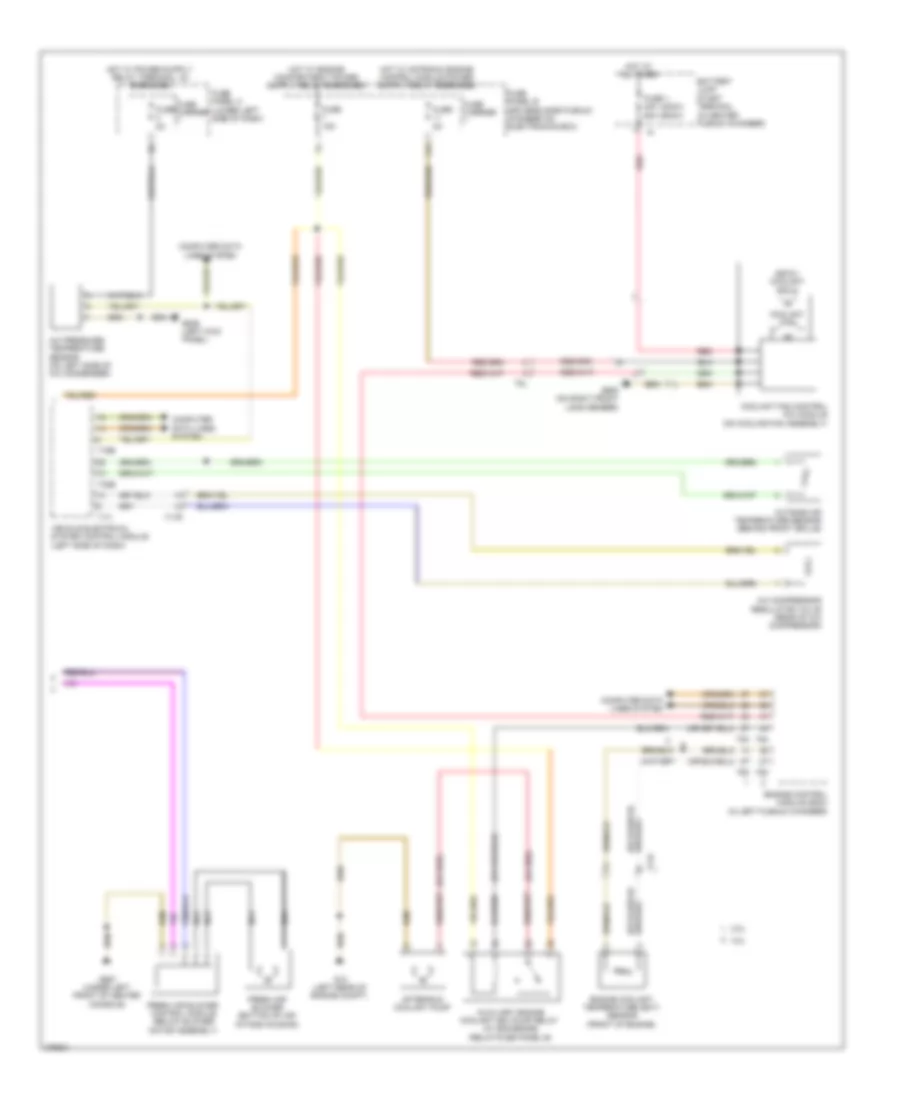
Automatic A/C Wiring Diagram, Basic (2 of 2) for Audi Q5 2.0T 2012
List of elements for Automatic A/C Wiring Diagram, Basic (2 of 2) for Audi Q5 2.0T 2012:
- (400w) (600w)
- (600w) coolant fan 2
- (or red)
- 11a
- 2.0l
- 3.2l
- A/c compressor regulator valve (rear of a/c compressor)
- A/c pressure/ temperature sensor (on left side of a/c condenser)
- After-run coolant pump
- Auxiliary engine coolant (ec) pump relay (w/ 8z4/8z6/8z9) (relay/fuse panel b)
- Battery jump start terminal (in center plenum chamber)
- Computer data lines system
- Coolant fan
- Coolant fan control (fc) module (on cooling fan assembly)
- Engine control module (ecm) (in left plenum chamber)
- Engine coolant temperature (ect) sensor (front of engine)
- Fresh air blower (bottom of air intake housing)
- Fresh air blower control module (below blower motor assembly)
- Fuse 1 40a 60a
- Fuse 15a
- Fuse 5a
- Fuse carrier
- Fuse panel b (driver's side plenum chamber on electronics box)
- Fuse panel c (lower left side of dash)
- G12 (left rear of engine compt)
- G639 (left kick panel)
- G685 (on right front long member)
- G687 (under left front of center console)
- Hot at all times
- Nca
- Outside air temperature sensor (behind front grille)
- Red
- T14f
- T16b
- T17i
- T17r
- T32b
- T5l
- T60
- T94
- Vehicle electrical system control module (left side of dash)
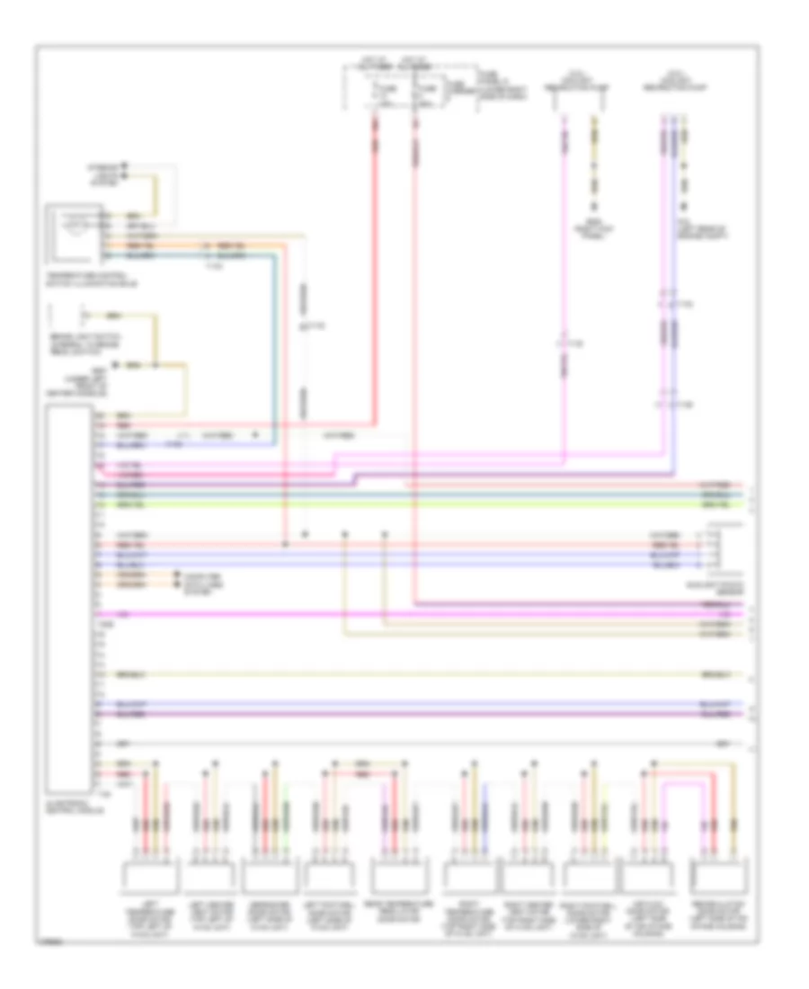
Automatic A/C Wiring Diagram, Comfort (1 of 3) for Audi Q5 2.0T 2012
List of elements for Automatic A/C Wiring Diagram, Comfort (1 of 3) for Audi Q5 2.0T 2012:
- (2.0l) coolant recircution pump
- (3.2l) coolant recircution pump
- 10a
- Air flow door motor (left side of air intake housing)
- Brake light switch (integral to brake pedal switch)
- Climatronic control module
- Computer data lines system
- Defroster door motor (left side of hvac unit)
- Fuse 10a
- Fuse 40a
- Fuse carrier
- Fuse panel d (lower right side of dash)
- G12 (left rear of engine compt)
- G638 (right kick panel)
- G687 (under left front of center console)
- Hot at all times
- Interior lights system
- Left center vent motor (top left of hvac unit)
- Left footwell door motor (left side of hvac unit)
- Left temperature door motor (top left of hvac unit)
- Rear temperature regulator door motor
- Recirculation door motor (left side of air intake housing)
- Red
- Right center vent motor (top right side of hvac unit)
- Right footwell door motor (lower right side of hvac unit)
- Right temperature door motor (top right side of hvac unit)
- Sunlight photo sensor
- T16i
- T17b
- T17d
- T17g
- T17q
- T20e
- Temperature control switch illumination bulb
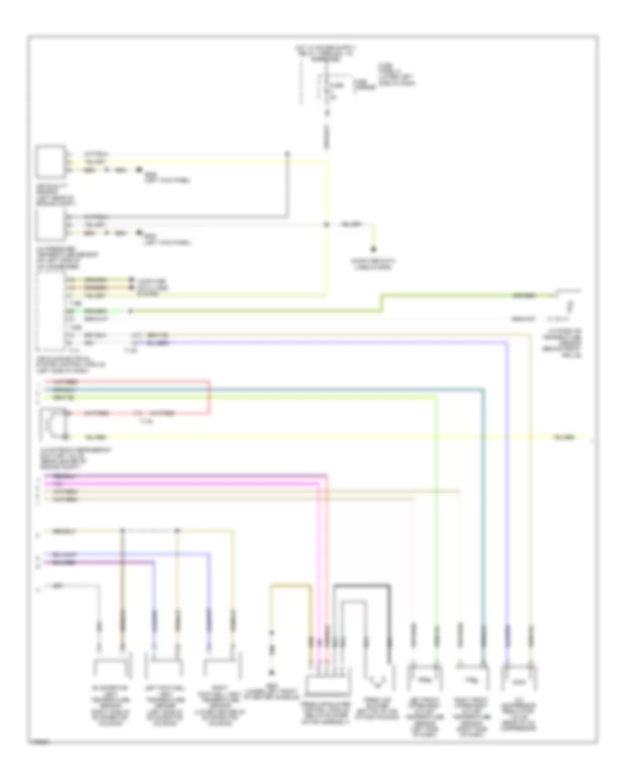
Automatic A/C Wiring Diagram, Comfort (2 of 3) for Audi Q5 2.0T 2012
List of elements for Automatic A/C Wiring Diagram, Comfort (2 of 3) for Audi Q5 2.0T 2012:
- A/c compressor regulator valve (rear of a/c compressor)
- A/c pressure/ temperature sensor (on left side of a/c condenser)
- Air quality sensor (left rear of engine compt)
- Climatronic refrigerant shut-off valve (rear center of engine compt)
- Computer data lines system
- Evaporator vent temperature sensor (right side of evaporator housing)
- Fresh air blower (bottom of air intake housing)
- Fresh air blower control module (below blower motor assembly)
- Fuse 5a
- Fuse carrier
- Fuse panel c (lower left side of dash)
- G639 (left kick panel)
- G687 (under left front of center console)
- Left footwell vent temperature sensor (left side of evaporator housing)
- Left front upper body outlet temperature sensor (left side of dash)
- Nca
- Outside air temperature sensor (behind front grille)
- Right footwell vent temperature sensor (lower center of evaporator housing)
- Right front upper body outlet temperature sensor (right side of dash)
- T16b
- T17i
- T17q
- T17r
- T32b
- Vehicle electrical system control module (left side of dash)
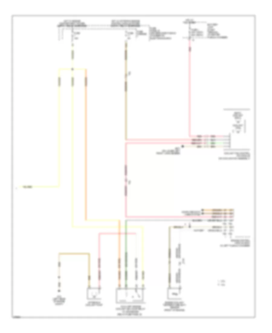
Automatic A/C Wiring Diagram, Comfort (3 of 3) for Audi Q5 2.0T 2012
List of elements for Automatic A/C Wiring Diagram, Comfort (3 of 3) for Audi Q5 2.0T 2012:
- (400w) (600w)
- (600w) coolant fan 2
- (or red)
- (relay/fuse panel b)
- (w/ 8z4/8z6/8z9)
- 11a
- 2.0l
- 3.2l
- After-run coolant pump
- Auxiliary engine coolant (ec) pump relay
- Battery jump start terminal (in center plenum chamber)
- Computer data lines system
- Coolant fan
- Coolant fan control (fc) module (on cooling fan assembly)
- Engine control module (ecm) (in left plenum chamber)
- Engine coolant temperature (ect) sensor (front of engine)
- Fuse 1 40a 60a
- Fuse 15a
- Fuse 5a
- Fuse carrier
- Fuse panel b (driver's side plenum chamber on electronics box)
- G12 (left rear of engine compt)
- G671 (on lower left front long member)
- Hot at all times
- Red
- T14f
- T5l
- T60
- T94
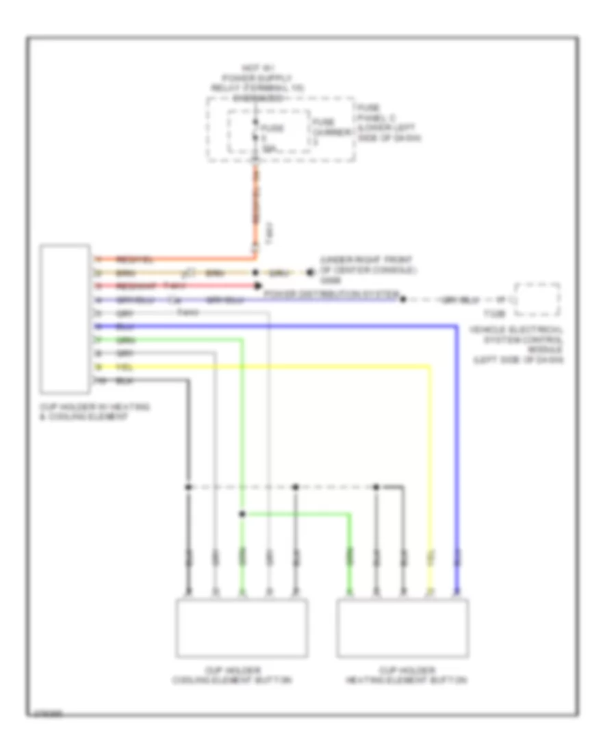
Heated And Cooled Cup Holder Wiring Diagram for Audi Q5 2.0T 2012
List of elements for Heated And Cooled Cup Holder Wiring Diagram for Audi Q5 2.0T 2012:
- (under right front of center console) g688
- Cup holder cooling element button
- Cup holder heating element button
- Cup holder w/ heating & cooling element
- Fuse 10a
- Fuse carrier
- Fuse panel c (lower left side of dash)
- Power distribution system
- T32b
- T4av
- Vehicle electrical system control module (left side of dash)

 Čeština
 Dansk
Dansk Deutsch
 Ελληνικά
 English
 English
 Español
 Suomi
Suomi Français
 Français
 עברית
עברית Hrvatski
 Magyar
 日本語
日本語 한국어
한국어 Nederlands
 Polski
 Português
 Português
 Română
 Русский
 Slovenčina
 Slovenščina
 Svenska
 Türkçe
 中文 (中国)