ENGINE PERFORMANCE
3.2L
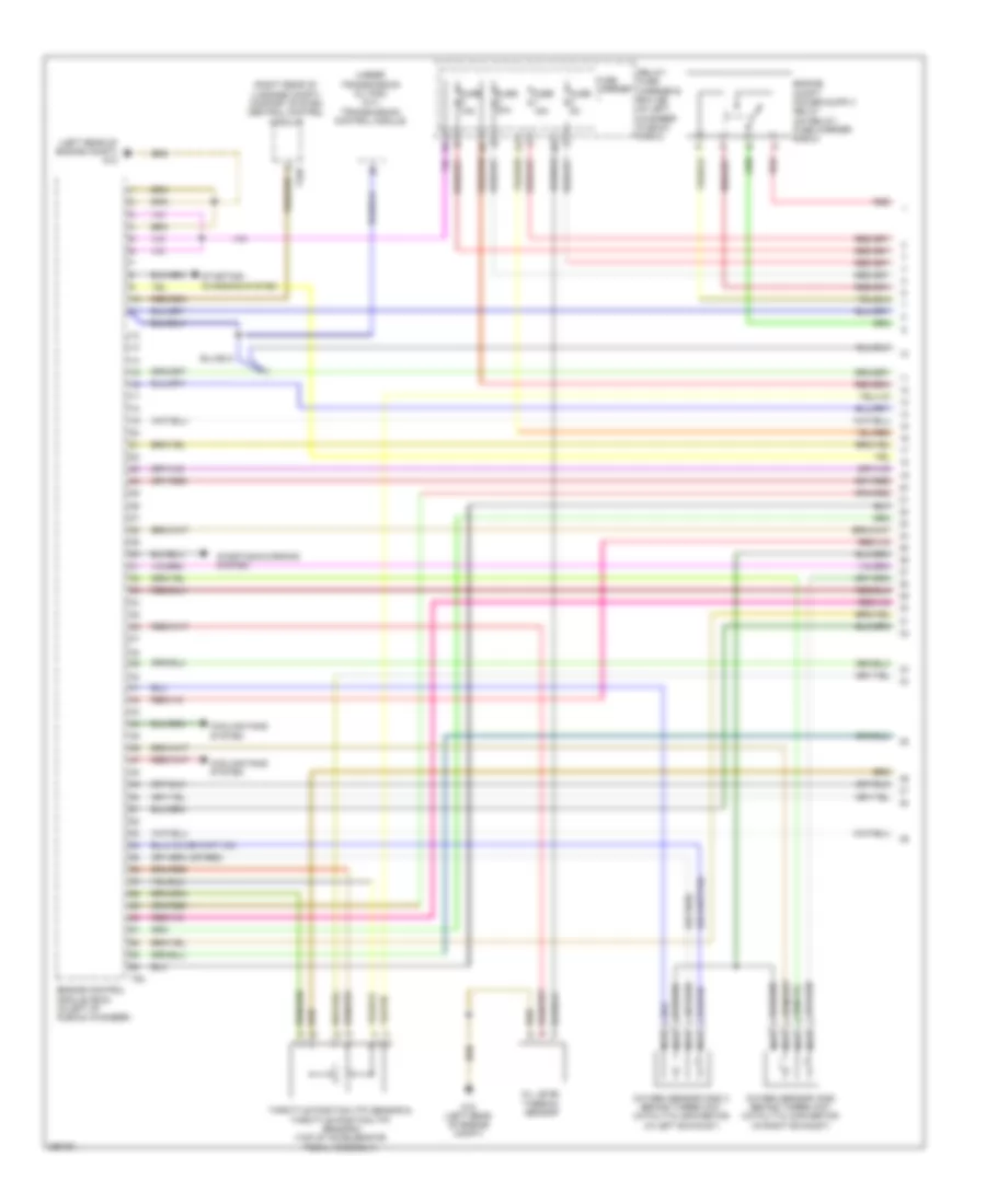
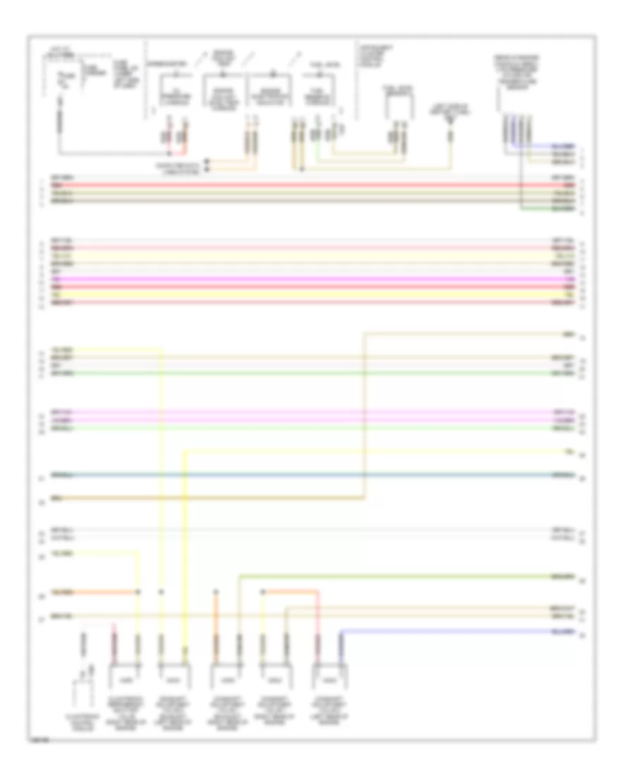
3.2L, Engine Performance Wiring Diagram (1 of 8) for Audi A5 Quattro 2008
List of elements for 3.2L, Engine Performance Wiring Diagram (1 of 8) for Audi A5 Quattro 2008:
- (left rear of engine compt) g12
- (or red)
- (right rear of luggage compt) comfort system central control module
- (under transmission oil pan) (a/t) transmission control module
- Cooling fans system
- Engine control module (ecm) (in left of plenum chamber)
- Fuse 15a
- Fuse 20a
- Fuse 5a
- Fuse carrier
- G12 (left rear of engine compt)
- Nca
- Oil level thermal sensor
- Oxygen sensor (02s) 2 behind three way catalytic convertor (in left exhaust)
- Oxygen sensor (o2s) behind three way catalytic convertor (in right exhaust)
- Red
- Relay/ fuse carrier e box sb (in left chamber plenum e-box)
- Starting/ charging system
- Starting/charging system
- T32d
- T94
- Throttle position (tp) sensor & throttle position (tp) sensor 2 (top of accelerator pedal assembly)
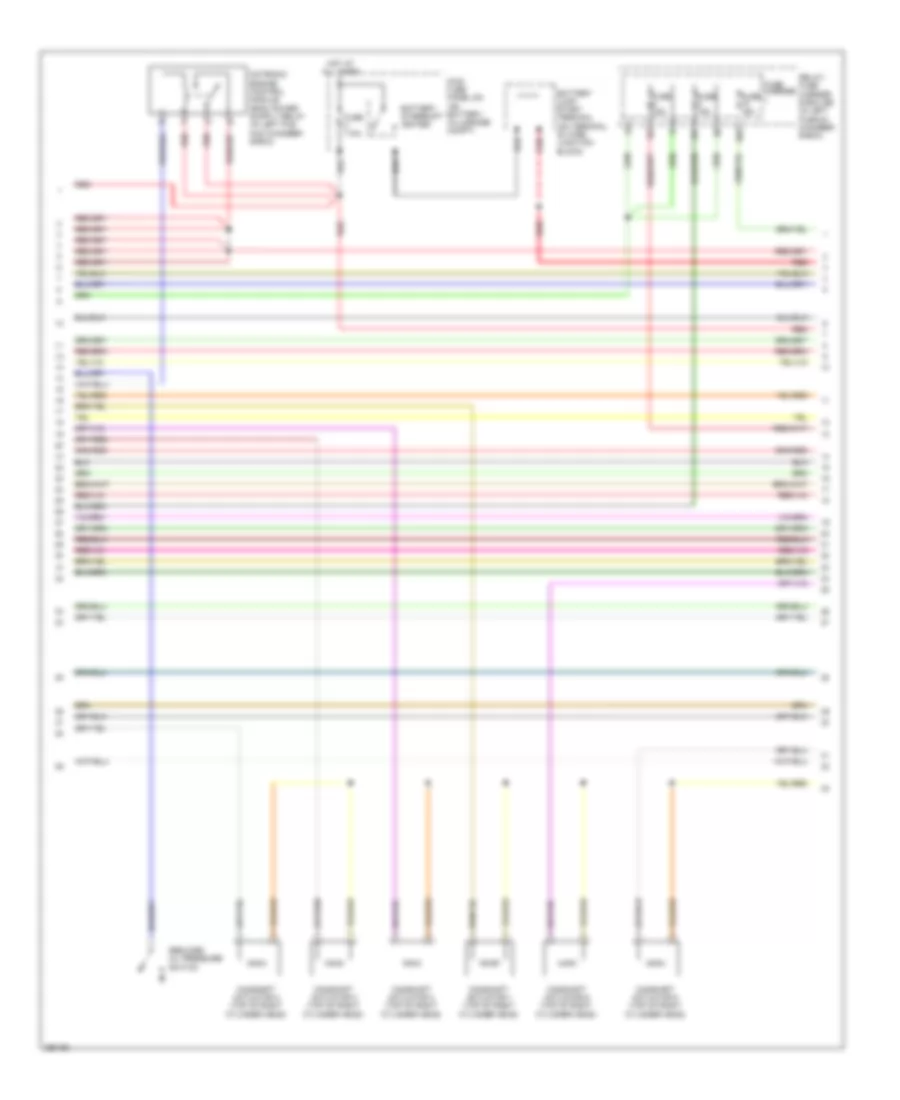
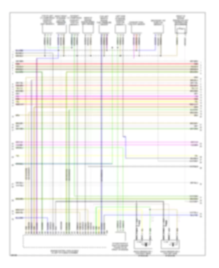
3.2L, Engine Performance Wiring Diagram (2 of 8) for Audi A5 Quattro 2008
List of elements for 3.2L, Engine Performance Wiring Diagram (2 of 8) for Audi A5 Quattro 2008:
- 10a
- Battery interrupt igniter
- Battery jump start terminal (on terminal 30 wire junction block)
- Camshaft actuator 1 (top of right cylinder head)
- Camshaft actuator 2 (top of right cylinder head)
- Camshaft actuator 3 (top of right cylinder head)
- Camshaft actuator 4 (top of right cylinder head)
- Camshaft actuator 5 (top of right cylinder head)
- Camshaft actuator 6 (top of right cylinder head)
- Fuse 110a
- Fuse 15a
- Fuse carrier
- Hot at all times
- Main fuse panel sa (on battery, in luggage compt)
- Red
- Reduced oil pressure switch
- Relay/ fuse carrier e box sb (in left plenum chamber e-box)
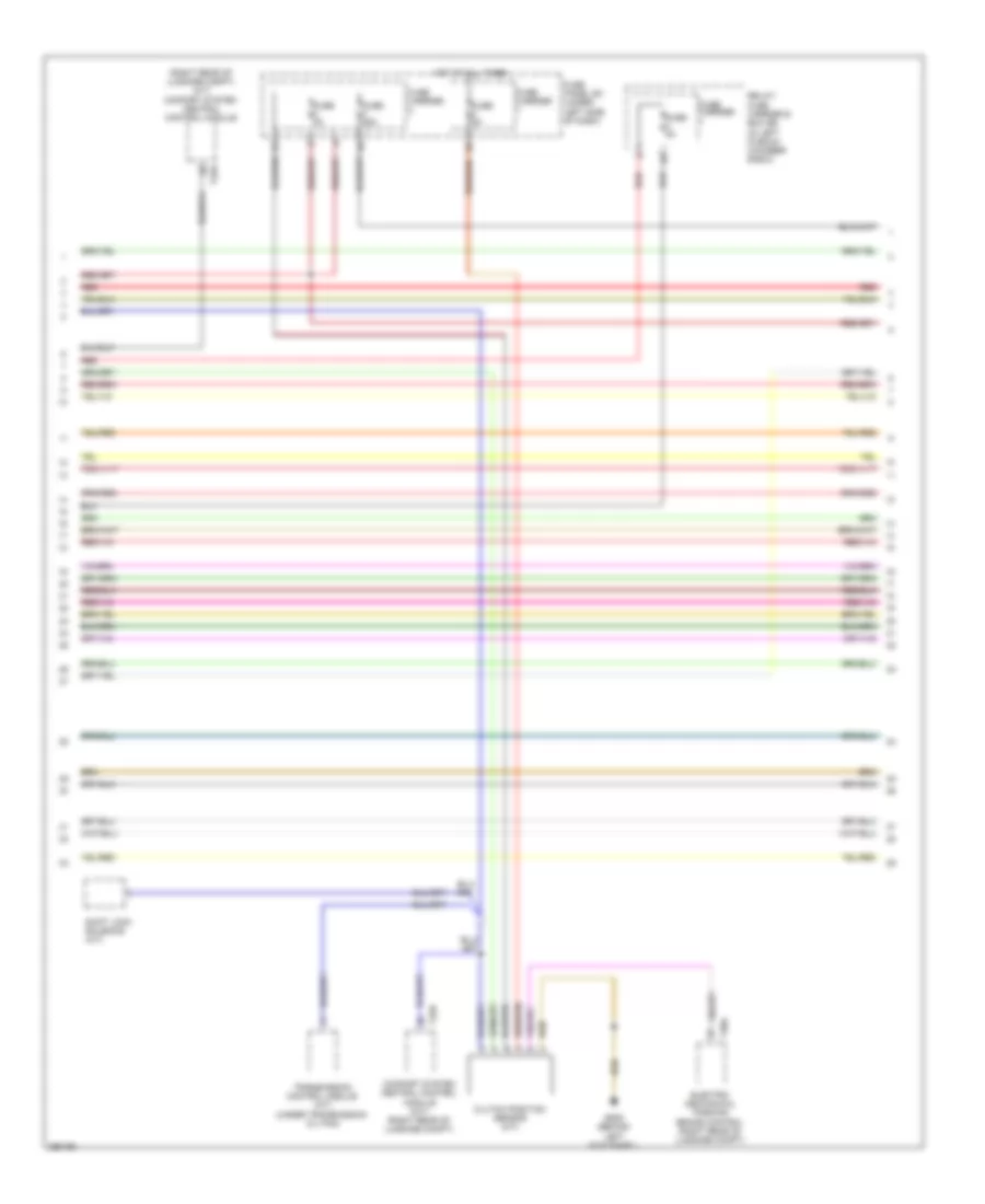
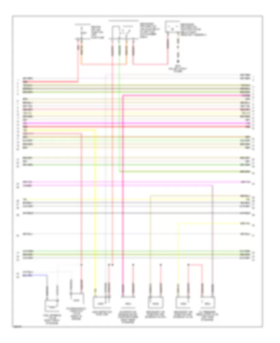
3.2L, Engine Performance Wiring Diagram (3 of 8) for Audi A5 Quattro 2008
List of elements for 3.2L, Engine Performance Wiring Diagram (3 of 8) for Audi A5 Quattro 2008:
- (right rear of luggage compt) (a/t) comfort system central control module
- Clutch position sensor (m/t)
- Comfort system central control module (m/t) (right rear of luggage compt)
- Electro- mechanical parking brake control (right rear of luggage compt)
- Fuse 25a
- Fuse 5a
- Fuse carrier
- Fuse panel sc (under left side of dash)
- G639 (behind left kick panel)
- Hot at all times
- Red
- Relay/ fuse carrier e box sb (in left plenum chamber e-box)
- Shift lock solenoid (a/t)
- T30a
- T32d
- Transmission control module (a/t) (under transmission oil pan)
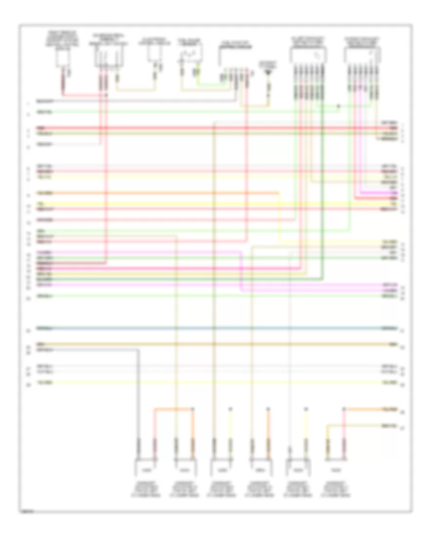
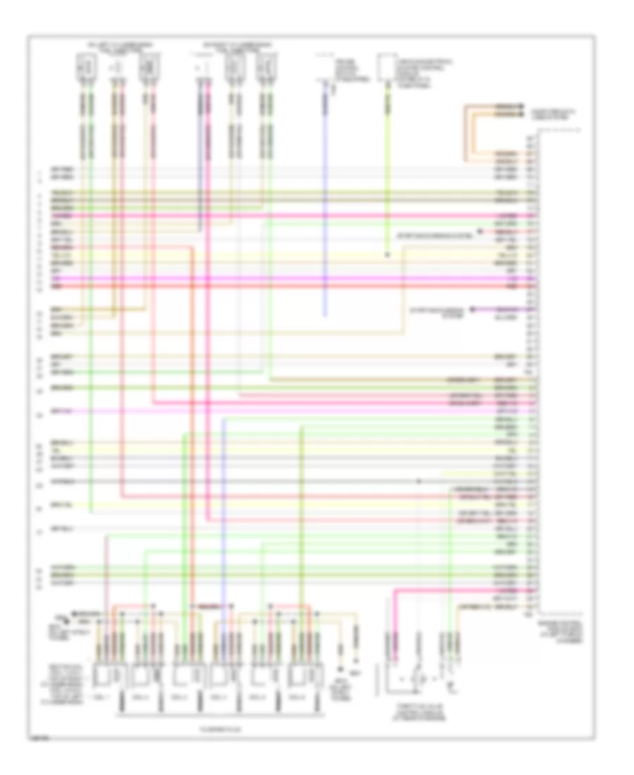
3.2L, Engine Performance Wiring Diagram (4 of 8) for Audi A5 Quattro 2008
List of elements for 3.2L, Engine Performance Wiring Diagram (4 of 8) for Audi A5 Quattro 2008:
- (in left exhaust) heated oxygen sensor (ho2s) 2
- (in right exhaust) heated oxygen sensor (h02s)
- (on brake pedal assembly) brake light switch
- (on right "c" panel) g663
- (right rear of luggage compt) comfort system central control module
- Camshaft actuator 10 (top of left cylinder head)
- Camshaft actuator 11 (top of left cylinder head)
- Camshaft actuator 12 (top of left cylinder head)
- Camshaft actuator 7 (top of left cylinder head)
- Camshaft actuator 8 (top of left cylinder head)
- Camshaft actuator 9 (top of left cylinder head)
- Climatronic control module
- Fuel gauge sensor
- Fuel pump (fp) control module
- Nca
- Red
- T20e
- T32d
- T5f
3.2L, Engine Performance Wiring Diagram (5 of 8) for Audi A5 Quattro 2008
List of elements for 3.2L, Engine Performance Wiring Diagram (5 of 8) for Audi A5 Quattro 2008:
- (left side of center tunel) g687
- (rear of engine) manifold absol- ute pressure/ intake air temperature sensor
- Camshaft adjustment valve 1 (exhaust) (right rear of engine)
- Camshaft adjustment valve 1 (right rear of engine)
- Camshaft adjustment valve 2 (exhaust) (left rear of engine)
- Camshaft adjustment valve 2 (left rear of engine)
- Climatronic control module
- Climatronic refrigerant shut-off valve (right rear of engine)
- Computer data lines system
- Engine coolant level/temp warning
- Engine coolant temp
- Engine electronics indicator
- Fuel level
- Fuel level sensor 2
- Fuel reserve warning
- Fuse 5a
- Fuse carrier
- Fuse panel sc (under left side of dash)
- Hot at all times
- Instrument cluster control module
- Oil pressure warning
- Red
- Speedometer
- T20e
- T32f
3.2L, Engine Performance Wiring Diagram (6 of 8) for Audi A5 Quattro 2008
List of elements for 3.2L, Engine Performance Wiring Diagram (6 of 8) for Audi A5 Quattro 2008:
- (front of engine) engine coolant temperature (ect) sensor
- (left side of engine) camshaft position sensor 4
- (on right cylinder bank)
- (rear of engine) engine speed (rpm) sensor
- (right front of engine) low fuel pressure sensor
- (top left rear of engine) fuel pressure sensor
- (top of left cylinder bank) camshaft position (cmp) sensor 2
- Camshaft posi- tion (cmp) sensor
- Camshaft position sensor 3
- Engine control module (ecm) (in left of plenum chamber)
- Intake manifold position sensor tuning valve (front of engine)
- Knock sensor (ks) 1 (top right rear of engine)
- Knock sensor (ks) 2 (top left side of engine)
- Nca
- Red
- Secondary air injection sensor 1
- T60
3.2L, Engine Performance Wiring Diagram (7 of 8) for Audi A5 Quattro 2008
List of elements for 3.2L, Engine Performance Wiring Diagram (7 of 8) for Audi A5 Quattro 2008:
- 30a
- Evaporative emission (evap) canister purge (right rear of engine)
- Fuel metering valve (right front of engine)
- G615 (on left strut tower)
- Intake manifold tuning (imt) valve (front of engine)
- Leak detection pump (ldp)
- Oil pressure regulator valve (left side of engine)
- Red
- Second- ary air injection (air) pump fuse
- Secondary air injection (air) pump motor (below right headlight assembly)
- Secondary air injection (air) pump relay (in left ple- num chamber e-box)
- Secondary air injection (air) solenoid valve
- Secondary air injection (air) solenoid valve 2
3.2L, Engine Performance Wiring Diagram (8 of 8) for Audi A5 Quattro 2008
List of elements for 3.2L, Engine Performance Wiring Diagram (8 of 8) for Audi A5 Quattro 2008:
- (on left cylinder bank) fuel injectors
- (on right cylinder bank) fuel injectors
- Coil 1
- Coil 2
- Coil 3
- Coil 4
- Coil 5
- Coil 6
- Computer data lines system
- Cruise control switch (if equipped)
- Engine control module (ecm) (in left plenum chamber)
- G600
- G601
- G615 (on left strut tower)
- Ignition coil (coil 1,2 & 3 : top of right cylinder bank) (coil 4,5 & 6 : top of left cylinder bank)
- Nca
- Red
- Starting/charging system
- T16f
- T60
- T94
- Throttle valve control module (at rear of engine)
- To spark plug
- Vehicle electrical system control module (on relay & fuse panel)

 Čeština
 Dansk
Dansk Deutsch
 Ελληνικά
 English
 English
 Español
 Suomi
Suomi Français
 Français
 עברית
עברית Hrvatski
 Magyar
 日本語
日本語 한국어
한국어 Nederlands
 Polski
 Português
 Português
 Română
 Русский
 Slovenčina
 Slovenščina
 Svenska
 Türkçe
 中文 (中国)